US8854157B2 - Balun comprising two conversion circuits each constituted by first to third FBARs - Google Patents

Balun comprising two conversion circuits each constituted by first to third FBARs Download PDF

Info

Publication number
US8854157B2
US8854157B2 US12/834,099 US83409910A US8854157B2 US 8854157 B2 US8854157 B2 US 8854157B2 US 83409910 A US83409910 A US 83409910A US 8854157 B2 US8854157 B2 US 8854157B2
Authority
US
United States
Prior art keywords
fbar
balun
conversion unit
fbars
conversion units
Prior art date
Legal status (The legal status is an assumption and is not a legal conclusion. Google has not performed a legal analysis and makes no representation as to the accuracy of the status listed.)
Active, expires
Application number
US12/834,099
Other versions
US20110095849A1 (en
Inventor
Duck Hwan Kim
Dal Ahn
Chul Soo Kim
In Sang Song
Yun Kwon Park
Jea Shik Shin
Hyung Rak Kim
Current Assignee (The listed assignees may be inaccurate. Google has not performed a legal analysis and makes no representation or warranty as to the accuracy of the list.)
Samsung Electronics Co Ltd
Original Assignee
Samsung Electronics Co Ltd
Priority date (The priority date is an assumption and is not a legal conclusion. Google has not performed a legal analysis and makes no representation as to the accuracy of the date listed.)
Filing date
Publication date
Application filed by Samsung Electronics Co Ltd filed Critical Samsung Electronics Co Ltd
Assigned to SAMSUNG ELECTRONICS CO., LTD. reassignment SAMSUNG ELECTRONICS CO., LTD. ASSIGNMENT OF ASSIGNORS INTEREST (SEE DOCUMENT FOR DETAILS). Assignors: AHN, DAL, KIM, CHUL SOO, KIM, DUCK HWAN, KIM, HYUNG RAK, PARK, YUN KWON, SHIN, JEA SHIK, SONG, IN SANG
Publication of US20110095849A1 publication Critical patent/US20110095849A1/en
Application granted granted Critical
Publication of US8854157B2 publication Critical patent/US8854157B2/en
Active legal-status Critical Current
Adjusted expiration legal-status Critical

Links

Images

Classifications

    • HELECTRICITY
    • H01ELECTRIC ELEMENTS
    • H01PWAVEGUIDES; RESONATORS, LINES, OR OTHER DEVICES OF THE WAVEGUIDE TYPE
    • H01P5/00Coupling devices of the waveguide type
    • H01P5/08Coupling devices of the waveguide type for linking dissimilar lines or devices
    • H01P5/10Coupling devices of the waveguide type for linking dissimilar lines or devices for coupling balanced lines or devices with unbalanced lines or devices
    • HELECTRICITY
    • H03ELECTRONIC CIRCUITRY
    • H03HIMPEDANCE NETWORKS, e.g. RESONANT CIRCUITS; RESONATORS
    • H03H9/00Networks comprising electromechanical or electro-acoustic elements; Electromechanical resonators
    • H03H9/0023Networks for transforming balanced signals into unbalanced signals and vice versa, e.g. baluns, or networks having balanced input and output
    • H03H9/0095Networks for transforming balanced signals into unbalanced signals and vice versa, e.g. baluns, or networks having balanced input and output using bulk acoustic wave devices

Definitions

  • the following description relates to a balun, and more particularly, to a balun including a film bulk acoustic resonator (FBAR) that may convert a balanced signal into an unbalanced signal, and/or convert an unbalanced signal into a balanced signal.
  • FBAR film bulk acoustic resonator
  • a balun may be used as a circuit/structure that may convert balanced signals into unbalanced signals or unbalanced signals into balanced signals.
  • the balun may include a passive element that may operate even when an input and an output are reversed.
  • a conventional balun is fabricated to include a plurality of transistors, or using a wavelength of a signal on a single plane.
  • the conventional balun is a part of a parallel type circuit such as a mixer, an amplifier, a multiplier, a phase shifter, and the like, and is generally implemented using a Lange coupler or an interdigital coupling.
  • the size of the balun using the wavelength of the signal plane may be significantly great.
  • a balun including a plurality of transistors may have a large difference between two outputs, and a supplementary circuit may need to be inserted in the balun to correct the difference between outputs.
  • the power consumption of the conventional balun is relatively great due to the plurality of transistors, and the yield of the circuit may be reduced by such power consumption. Accordingly, these two types of baluns may cause a reduction in a degree of integration of a semiconductor, and therefore may not be readily implemented in an integrated circuit.
  • a balun including two conversion units to control the phase of an input signal, the two conversion units including at least one film bulk acoustic resonator (FBAR) and at least one passive element that is connected with the at least one FBAR.
  • FBAR film bulk acoustic resonator
  • At least one of the two conversion units may include two FBARs connected to a ground, and the passive element may be located between the two FBARs.
  • At least one of the two conversion units may include two passive elements connected to a ground, and the FBAR may be located between the two passive elements.
  • At least one of the two conversion units may include two FBARs, and the passive element may be located between the two FBARs and connected to a ground.
  • At least one of the two conversion units may include two passive elements, and the FBAR may be located between the two passive elements and may be connected to a ground.
  • the passive element may be at least one of a capacitor and an inductor.
  • the FBAR may be at least one of a bulk acoustic wave resonator (BAWR) and a thin film bulk acoustic resonator (TFBAR).
  • BAWR bulk acoustic wave resonator
  • TFBAR thin film bulk acoustic resonator
  • the FBAR may be connected in series with a capacitor to change a frequency response characteristic.
  • the FBAR may be connected in parallel with a capacitor to change a frequency response characteristic.
  • the FBAR may be connected in series with an inductor to change a frequency response characteristic.
  • the FBAR may be connected in parallel with an inductor to change a frequency response characteristic.
  • a balun including two conversion units to control the phase of an input signal, the two conversion units including a first FBAR connected to a ground, a second FBAR connected to the ground, and a third FBAR located between the first FBAR and the second FBAR.
  • a balun including two conversion units to control the phase of an input signal, the two conversion units including a first FBAR, a second FBAR, and a third FBAR located between the first FBAR and the second FBAR, the third FBAR also being connected to a ground.
  • FIG. 1 is a diagram illustrating an example of a balun.
  • FIGS. 2 through 11 are diagrams illustrating examples of a conversion unit.
  • FIGS. 12 through 15 are diagrams illustrating examples of a film bulk acoustic resonator (FBAR).
  • FBAR film bulk acoustic resonator
  • FIG. 16 is a diagram illustrating another example of a conversion unit.
  • FIG. 1 illustrates an example of a balun.
  • balun 100 includes two conversion units 110 .
  • Each conversion unit 110 includes a film bulk acoustic resonator (FBAR) 120 and a passive element 130 connected with the FBAR.
  • FBAR film bulk acoustic resonator
  • the balun 100 may receive as an input a signal via a first port 101 .
  • the conversion unit 110 may include at least one FBAR 120 and at least one passive element 130 connected with the at least one FBAR 120 . However, it should be understood that the conversion unit 110 may include more than one FBAR 120 and/or more than one passive element 130 .
  • the conversion unit 110 may control a phase of the inputted signal via the first port 101 .
  • the conversion unit 110 may convert the inputted signal into a signal having the same amplitude as that of the inputted signal.
  • the conversion unit 110 may convert the inputted signal into a signal having a phase difference of 90 degrees between the phase of the inputted signal and a phase of the current signal, while at the same time having the same amplitude.
  • the passive element 130 may be, for example, a capacitor and/or an inductor.
  • the FBAR 120 may be, for example, a bulk acoustic wave resonator (BAWR), a thin film bulk acoustic resonator (TFBAR), and the like.
  • the signal converted by the conversion unit 110 may be outputted via a second port 102 and/or a third port 103 .
  • the conversion unit 110 may convert the inputted signal via the first port 101 , such that the difference between the phase of the outputted signal via the second port 102 and the phase of the outputted signal via the third port 103 is 180 degrees.
  • FIGS. 2 through 11 illustrate various examples of a conversion unit.
  • conversion unit 200 includes a first FBAR 210 , a second FBAR 220 , and a third FBAR 230 .
  • a balun may include two conversion units to control a phase of an input signal, wherein each of the two conversion units are configured the same as the conversion unit 200 .
  • the third FBAR 230 is located between the first FBAR 210 and the second FBAR 220 , and the third FBAR 230 may also be connected with a ground.
  • the conversion unit 200 includes the three FBARs 210 , 220 , and 230 that are configured in a T-shape.
  • the conversion unit 300 may be used to control the phase of an input signal and includes a first FBAR 310 connected with a ground, a second FBAR 320 connected with the ground, and a third FBAR 330 located between the first FBAR 310 and the second FBAR 320 .
  • a balun may include two conversion units to control a phase of an input signal, wherein each of the two conversion units are the same as the conversion unit 300 .
  • the conversion unit 300 includes the three FBARs 310 , 320 , and 330 that are configured in the shape of a ⁇ symbol.
  • the balun may include two conversion units to control the phase of the input signal, and any one of the two conversion units may include two FBARs and a passive element.
  • the passive element may be located between the two FBARs, and connected with a ground.
  • conversion unit 400 includes two FBARs 410 and a capacitor 420 .
  • the capacitor 420 is located between the two FBARs 410 , and connected with a ground.
  • the conversion unit 400 includes the two FBARs 410 and the capacitor 420 that are configured in a T-shape.
  • conversion unit 500 includes two FBARs 510 and an inductor 520 .
  • the inductor 520 may be located between the two FBARs 510 , and connected with a ground.
  • the conversion unit 500 includes the two FBARs 510 and the inductor 520 that are configured in a T-shape.
  • the balun may include two conversion units to control a phase of an input signal, and any one of the two conversion units may include two passive elements and an FBAR.
  • the FBAR may be located between the two passive elements and connected with a ground.
  • conversion unit 600 includes two capacitors 610 and an FBAR 620 located between the two capacitors 610 and connected with a ground.
  • the conversion unit 600 includes the two capacitors 610 and the FBAR 620 and that are configured in a T-shape.
  • conversion unit 700 includes two inductors 710 and an FBAR 720 .
  • the FBAR 720 may be located between the two inductors 710 and connected with a ground.
  • the conversion unit 700 includes the two inductors 710 and the FBAR 720 that are configured in a T-shape.
  • the balun may include two conversion units to control the phase of an input signal, and, as is further discussed herein, any one of the two conversion units may include two FBARs and a passive element.
  • the two FBARs may be connected with a ground, and the passive element may be located between the two FBARs as shown in the examples of FIGS. 8 and 9 .
  • conversion unit 800 includes two FBARs 810 and a capacitor 820 .
  • the two FBARs 810 may be connected with a ground, and the capacitor 820 may be located between the two FBARs 810 .
  • the conversion unit 800 includes the two FBARs 810 and the capacitor 820 configured in the shape of a ⁇ symbol.
  • conversion unit 900 includes two FBARs 910 and an inductor 920 .
  • the two FBARs 910 may be connected with a ground, and the inductor 920 may be located between the two FBARs 910 .
  • the conversion unit 900 includes the two FBARs 910 and the inductor 920 configured in the shape of a ⁇ symbol.
  • the balun may include two conversion units to control the phase of an input signal, and any one of the two conversion units may include two passive elements and an FBAR.
  • the two passive elements may be connected with a ground, and the FBAR may be located between the two passive elements.
  • conversion unit 1000 includes two capacitors 1010 and an FBAR 1020 .
  • the two capacitors 1010 may be connected with a ground, and the FBAR 1020 may be located between the two capacitors 1010 .
  • the conversion unit 1000 includes the two capacitors 1010 and the FBAR 1020 that are configured in the shape of a ⁇ symbol.
  • conversion unit 1100 includes two inductors 1110 and an FBAR 1120 .
  • the two inductors 1110 may be connected with a ground, and the FBAR 1120 may be located between the two inductors 1110 .
  • the conversion unit 1100 includes the two inductors 1110 and the FBAR 1120 that are configured in the shape of a ⁇ symbol.
  • the balun may include two conversion units, and each of the two conversion units may be one of the conversion units illustrated in FIGS. 2 through 11 .
  • the first conversion unit may include three FBARs configured in a T-shape as illustrated in the example shown in FIG. 2
  • the second conversion unit may include three FBARs configured in a shape of the symbol ⁇ as illustrated in the example shown in FIG. 3 .
  • FIGS. 12 to 15 illustrate various examples of an FBAR.
  • FBAR 1200 is connected in series with a capacitor 1210 to obtain a changed frequency response characteristic.
  • FBAR 1300 is connected in series with an inductor 1310 to obtain a changed frequency response characteristic.
  • FBAR 1400 may be connected in parallel with a capacitor 1410 to obtain a changed frequency response characteristic.
  • FBAR 1500 is connected in parallel with an inductor 1510 to obtain a changed frequency response characteristic.
  • the balun may include two conversion units, and each of the two conversion units may include at least one FBAR.
  • the at least one FBAR may be connected in series or in parallel with a capacitor or an inductor to obtain the changed frequency response characteristic, as illustrated in the examples shown in FIGS. 12 through 15 .
  • a configuration in which the at least one FBAR is connected in series or in parallel with the capacitor or the inductor to obtain the changed frequency response characteristic is described with reference to FIG. 16 .
  • FIG. 16 illustrates another example of a conversion unit.
  • an additional inductor 1602 is added to conversion unit 1620 to obtain a changed frequency response characteristic.
  • a conversion unit 1610 includes two capacitors and an FBAR 1601 .
  • the two capacitors may be connected with a ground, and the FBAR 1601 may be located between the two capacitors.
  • the FBAR 1601 may be connected in series with an inductor 1602 to obtain a changed frequency response characteristic.
  • the conversion unit 1620 includes the FBAR 1601 connected in series with the inductor 1602 to obtain the changed frequency response characteristic with the conversion unit 1610 .
  • the example baluns described herein including one or more FBARs, may have a minimal difference between two outputs, without the need for a supplementary circuit to be inserted in the balun to correct the difference between outputs.
  • the power consumption of the baluns described herein may be reduced in comparison to the conventional balun including the plurality of transistors.
  • the yield of the circuit may be reduced.

Landscapes

  • Physics & Mathematics (AREA)
  • Acoustics & Sound (AREA)
  • Piezo-Electric Or Mechanical Vibrators, Or Delay Or Filter Circuits (AREA)

Abstract

Disclosed is a balun including a film bulk acoustic resonator (FBAR). The balun may be implemented using the FBAR to fabricate a small sized balun. Also, the balun may be implemented using the FBAR, thereby reducing a difference in two outputs.

Description

CROSS-REFERENCE TO RELATED APPLICATION(S)
This application claims the benefit under 35 U.S.C. §119(a) of Korean Patent Application No. 10-2009-0102540, filed on Oct. 28, 2009, in the Korean Intellectual Property Office, the entire disclosure of which is incorporated herein by reference for all purposes.
BACKGROUND
1. Field
The following description relates to a balun, and more particularly, to a balun including a film bulk acoustic resonator (FBAR) that may convert a balanced signal into an unbalanced signal, and/or convert an unbalanced signal into a balanced signal.
2. Description of Related Art
A balun may be used as a circuit/structure that may convert balanced signals into unbalanced signals or unbalanced signals into balanced signals. The balun may include a passive element that may operate even when an input and an output are reversed.
A conventional balun is fabricated to include a plurality of transistors, or using a wavelength of a signal on a single plane. The conventional balun is a part of a parallel type circuit such as a mixer, an amplifier, a multiplier, a phase shifter, and the like, and is generally implemented using a Lange coupler or an interdigital coupling.
However, the size of the balun using the wavelength of the signal plane may be significantly great. Also, a balun including a plurality of transistors may have a large difference between two outputs, and a supplementary circuit may need to be inserted in the balun to correct the difference between outputs. In addition, the power consumption of the conventional balun is relatively great due to the plurality of transistors, and the yield of the circuit may be reduced by such power consumption. Accordingly, these two types of baluns may cause a reduction in a degree of integration of a semiconductor, and therefore may not be readily implemented in an integrated circuit.
SUMMARY OF THE INVENTION
In one general aspect, there is provided, a balun including two conversion units to control the phase of an input signal, the two conversion units including at least one film bulk acoustic resonator (FBAR) and at least one passive element that is connected with the at least one FBAR.
At least one of the two conversion units may include two FBARs connected to a ground, and the passive element may be located between the two FBARs.
At least one of the two conversion units may include two passive elements connected to a ground, and the FBAR may be located between the two passive elements.
At least one of the two conversion units may include two FBARs, and the passive element may be located between the two FBARs and connected to a ground.
At least one of the two conversion units may include two passive elements, and the FBAR may be located between the two passive elements and may be connected to a ground.
The passive element may be at least one of a capacitor and an inductor.
The FBAR may be at least one of a bulk acoustic wave resonator (BAWR) and a thin film bulk acoustic resonator (TFBAR).
The FBAR may be connected in series with a capacitor to change a frequency response characteristic.
The FBAR may be connected in parallel with a capacitor to change a frequency response characteristic.
The FBAR may be connected in series with an inductor to change a frequency response characteristic.
The FBAR may be connected in parallel with an inductor to change a frequency response characteristic.
In another aspect, there is provided a balun including two conversion units to control the phase of an input signal, the two conversion units including a first FBAR connected to a ground, a second FBAR connected to the ground, and a third FBAR located between the first FBAR and the second FBAR.
In another aspect, there is provided a balun including two conversion units to control the phase of an input signal, the two conversion units including a first FBAR, a second FBAR, and a third FBAR located between the first FBAR and the second FBAR, the third FBAR also being connected to a ground.
Other features and aspects may be apparent from the following description, the drawings, and the claims.
BRIEF DESCRIPTION OF THE DRAWINGS
FIG. 1 is a diagram illustrating an example of a balun.
FIGS. 2 through 11 are diagrams illustrating examples of a conversion unit.
FIGS. 12 through 15 are diagrams illustrating examples of a film bulk acoustic resonator (FBAR).
FIG. 16 is a diagram illustrating another example of a conversion unit.
Throughout the drawings and the description, unless otherwise described, the same drawing reference numerals should be understood to refer to the same elements, features, and structures. The relative size and depiction of these elements may be exaggerated for clarity, illustration, and convenience.
DETAILED DESCRIPTION OF THE INVENTION
The following description is provided to assist the reader in gaining a comprehensive understanding of the methods, apparatuses, and/or systems described herein. Accordingly, various changes, modifications, and equivalents of the methods, apparatuses, and/or systems described herein may be suggested to those of ordinary skill in the art. The progression of processing steps and/or operations described is an example; however, the sequence of steps and/or operations is not limited to that set forth herein and may be changed as is known in the art, with the exception of steps and/or operations necessarily occurring in a certain order. Also, description of well-known functions and constructions may be omitted for increased clarity and conciseness.
FIG. 1 illustrates an example of a balun.
Referring to FIG. 1, balun 100 includes two conversion units 110. Each conversion unit 110 includes a film bulk acoustic resonator (FBAR) 120 and a passive element 130 connected with the FBAR.
The balun 100 may receive as an input a signal via a first port 101.
The conversion unit 110 may include at least one FBAR 120 and at least one passive element 130 connected with the at least one FBAR 120. However, it should be understood that the conversion unit 110 may include more than one FBAR 120 and/or more than one passive element 130.
The conversion unit 110 may control a phase of the inputted signal via the first port 101. According to various embodiments, the conversion unit 110 may convert the inputted signal into a signal having the same amplitude as that of the inputted signal. For example, the conversion unit 110 may convert the inputted signal into a signal having a phase difference of 90 degrees between the phase of the inputted signal and a phase of the current signal, while at the same time having the same amplitude.
The passive element 130 may be, for example, a capacitor and/or an inductor. The FBAR 120 may be, for example, a bulk acoustic wave resonator (BAWR), a thin film bulk acoustic resonator (TFBAR), and the like.
The signal converted by the conversion unit 110 may be outputted via a second port 102 and/or a third port 103. For example, the conversion unit 110 may convert the inputted signal via the first port 101, such that the difference between the phase of the outputted signal via the second port 102 and the phase of the outputted signal via the third port 103 is 180 degrees.
FIGS. 2 through 11 illustrate various examples of a conversion unit.
Referring to FIG. 2, conversion unit 200 includes a first FBAR 210, a second FBAR 220, and a third FBAR 230. A balun may include two conversion units to control a phase of an input signal, wherein each of the two conversion units are configured the same as the conversion unit 200. In this example, the third FBAR 230 is located between the first FBAR 210 and the second FBAR 220, and the third FBAR 230 may also be connected with a ground.
In this example, the conversion unit 200 includes the three FBARs 210, 220, and 230 that are configured in a T-shape.
Referring to FIG. 3, the conversion unit 300 may be used to control the phase of an input signal and includes a first FBAR 310 connected with a ground, a second FBAR 320 connected with the ground, and a third FBAR 330 located between the first FBAR 310 and the second FBAR 320. A balun may include two conversion units to control a phase of an input signal, wherein each of the two conversion units are the same as the conversion unit 300.
In this example, the conversion unit 300 includes the three FBARs 310, 320, and 330 that are configured in the shape of a π symbol.
Accordingly, the balun may include two conversion units to control the phase of the input signal, and any one of the two conversion units may include two FBARs and a passive element. For example, the passive element may be located between the two FBARs, and connected with a ground.
Referring to FIG. 4, conversion unit 400 includes two FBARs 410 and a capacitor 420. In this example, the capacitor 420 is located between the two FBARs 410, and connected with a ground. Also in this example, the conversion unit 400 includes the two FBARs 410 and the capacitor 420 that are configured in a T-shape.
Referring to FIG. 5, conversion unit 500 includes two FBARs 510 and an inductor 520. For example, the inductor 520 may be located between the two FBARs 510, and connected with a ground. In this example, the conversion unit 500 includes the two FBARs 510 and the inductor 520 that are configured in a T-shape.
Accordingly, the balun may include two conversion units to control a phase of an input signal, and any one of the two conversion units may include two passive elements and an FBAR. For example, the FBAR may be located between the two passive elements and connected with a ground.
Referring to FIG. 6, conversion unit 600 includes two capacitors 610 and an FBAR 620 located between the two capacitors 610 and connected with a ground. In this example, the conversion unit 600 includes the two capacitors 610 and the FBAR 620 and that are configured in a T-shape.
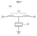
Referring to FIG. 7, conversion unit 700 includes two inductors 710 and an FBAR 720. For example, the FBAR 720 may be located between the two inductors 710 and connected with a ground. In this example, the conversion unit 700 includes the two inductors 710 and the FBAR 720 that are configured in a T-shape.
According to various aspects, the balun may include two conversion units to control the phase of an input signal, and, as is further discussed herein, any one of the two conversion units may include two FBARs and a passive element. For example, the two FBARs may be connected with a ground, and the passive element may be located between the two FBARs as shown in the examples of FIGS. 8 and 9.
Referring to FIG. 8, conversion unit 800 includes two FBARs 810 and a capacitor 820. For example, the two FBARs 810 may be connected with a ground, and the capacitor 820 may be located between the two FBARs 810. In this example, the conversion unit 800 includes the two FBARs 810 and the capacitor 820 configured in the shape of a π symbol.
Referring to FIG. 9, conversion unit 900 includes two FBARs 910 and an inductor 920. For example, the two FBARs 910 may be connected with a ground, and the inductor 920 may be located between the two FBARs 910. In this example, the conversion unit 900 includes the two FBARs 910 and the inductor 920 configured in the shape of a π symbol.
Accordingly, the balun may include two conversion units to control the phase of an input signal, and any one of the two conversion units may include two passive elements and an FBAR. As another example, the two passive elements may be connected with a ground, and the FBAR may be located between the two passive elements.
Referring to FIG. 10, conversion unit 1000 includes two capacitors 1010 and an FBAR 1020. For example, the two capacitors 1010 may be connected with a ground, and the FBAR 1020 may be located between the two capacitors 1010. In this example, the conversion unit 1000 includes the two capacitors 1010 and the FBAR 1020 that are configured in the shape of a π symbol.
Referring to FIG. 11, conversion unit 1100 includes two inductors 1110 and an FBAR 1120. For example, the two inductors 1110 may be connected with a ground, and the FBAR 1120 may be located between the two inductors 1110. In this example, the conversion unit 1100 includes the two inductors 1110 and the FBAR 1120 that are configured in the shape of a π symbol.
Accordingly, the balun may include two conversion units, and each of the two conversion units may be one of the conversion units illustrated in FIGS. 2 through 11. For example, as for the balun including a first conversion unit and a second conversion unit, the first conversion unit may include three FBARs configured in a T-shape as illustrated in the example shown in FIG. 2, and the second conversion unit may include three FBARs configured in a shape of the symbol π as illustrated in the example shown in FIG. 3.
FIGS. 12 to 15 illustrate various examples of an FBAR.
Referring to FIG. 12, FBAR 1200 is connected in series with a capacitor 1210 to obtain a changed frequency response characteristic.
Referring to FIG. 13, FBAR 1300 is connected in series with an inductor 1310 to obtain a changed frequency response characteristic.
Referring to FIG. 14, FBAR 1400 may be connected in parallel with a capacitor 1410 to obtain a changed frequency response characteristic.
Referring to FIG. 15, FBAR 1500 is connected in parallel with an inductor 1510 to obtain a changed frequency response characteristic.
Accordingly, the balun may include two conversion units, and each of the two conversion units may include at least one FBAR. For example, the at least one FBAR may be connected in series or in parallel with a capacitor or an inductor to obtain the changed frequency response characteristic, as illustrated in the examples shown in FIGS. 12 through 15. A configuration in which the at least one FBAR is connected in series or in parallel with the capacitor or the inductor to obtain the changed frequency response characteristic is described with reference to FIG. 16.
FIG. 16 illustrates another example of a conversion unit. In this example, an additional inductor 1602 is added to conversion unit 1620 to obtain a changed frequency response characteristic.
Referring to FIG. 16, a conversion unit 1610 includes two capacitors and an FBAR 1601. For example, the two capacitors may be connected with a ground, and the FBAR 1601 may be located between the two capacitors. Also, the FBAR 1601 may be connected in series with an inductor 1602 to obtain a changed frequency response characteristic. In this example, the conversion unit 1620 includes the FBAR 1601 connected in series with the inductor 1602 to obtain the changed frequency response characteristic with the conversion unit 1610.
Accordingly, the example baluns described herein, including one or more FBARs, may have a minimal difference between two outputs, without the need for a supplementary circuit to be inserted in the balun to correct the difference between outputs. In addition, the power consumption of the baluns described herein may be reduced in comparison to the conventional balun including the plurality of transistors. Thus, the yield of the circuit may be reduced.
A number of examples have been described above. Nevertheless, it should be understood that various modifications may be made. For example, suitable results may be achieved if the described techniques are performed in a different order and/or if components in a described system, architecture, device, or circuit are combined in a different manner and/or replaced or supplemented by other components or their equivalents. Accordingly, other implementations are within the scope of the following claims.

Claims (2)

What is claimed is:
1. A balun, comprising:
two conversion units configured to control the phase of an input signal, the two conversion units each consisting of a first FBAR, a second FBAR, and a third FBAR located between the first FBAR and the second FBAR, the third FBAR being connected to a ground; and
a first port connected between the two conversion units and which is configured to receive an unbalanced signal, a second port connected to a first conversion unit from among the two conversion units, and a third port connected to a second conversion unit from among the two conversion units,
wherein the two conversion units are connected to each other in series.
2. The balun of claim 1, wherein the two conversion units convert a signal inputted via the first port, such that the difference between a phase of a signal outputted via the second port and a phase of an outputted signal via the third port is 180 degrees.
US12/834,099 2009-10-28 2010-07-12 Balun comprising two conversion circuits each constituted by first to third FBARs Active 2031-06-27 US8854157B2 (en)

Applications Claiming Priority (2)

Application Number Priority Date Filing Date Title
KR10-2009-0102540 2009-10-28
KR1020090102540A KR101628240B1 (en) 2009-10-28 2009-10-28 Balun using Film Bulk Acoustic Resonator

Publications (2)

Publication Number Publication Date
US20110095849A1 US20110095849A1 (en) 2011-04-28
US8854157B2 true US8854157B2 (en) 2014-10-07

Family

ID=43897915

Family Applications (1)

Application Number Title Priority Date Filing Date
US12/834,099 Active 2031-06-27 US8854157B2 (en) 2009-10-28 2010-07-12 Balun comprising two conversion circuits each constituted by first to third FBARs

Country Status (2)

Country Link
US (1) US8854157B2 (en)
KR (1) KR101628240B1 (en)

Families Citing this family (1)

* Cited by examiner, † Cited by third party
Publication number Priority date Publication date Assignee Title
KR101616941B1 (en) * 2009-09-07 2016-04-29 삼성전자주식회사 Phase shifter using bulk acoustic wave resonator

Citations (10)

* Cited by examiner, † Cited by third party
Publication number Priority date Publication date Assignee Title
US20030179053A1 (en) * 2001-03-23 2003-09-25 Robert Aigner Filter device
KR20040079412A (en) 2002-01-09 2004-09-14 노키아 코포레이션 Bulk acoustic wave resonator with two piezoelectric layers as balun in filters and duplexers
US6803835B2 (en) 2001-08-30 2004-10-12 Agilent Technologies, Inc. Integrated filter balun
JP2006074749A (en) 2004-08-04 2006-03-16 Matsushita Electric Ind Co Ltd Antenna duplexer, and high-frequency module and communication device using the same
KR20060027506A (en) 2004-09-23 2006-03-28 삼성전기주식회사 Unbalanced input / output structure FARAR filter
US7102460B2 (en) 2003-04-17 2006-09-05 Epcos Ag Duplexer with extended functionality
US7212085B2 (en) 2004-12-30 2007-05-01 Delta Electronics, Inc. Filter assembly with unbalanced to balanced conversion and reduced noise
US7242268B2 (en) * 2002-10-25 2007-07-10 Hitachi Metals, Ltd. Unbalanced-balanced multiband filter module
US7446629B2 (en) * 2004-08-04 2008-11-04 Matsushita Electric Industrial Co., Ltd. Antenna duplexer, and RF module and communication apparatus using the same
US20090273408A1 (en) * 2008-04-30 2009-11-05 Fujitsu Limited Filter duplexer and communication device

Family Cites Families (3)

* Cited by examiner, † Cited by third party
Publication number Priority date Publication date Assignee Title
JP3973915B2 (en) * 2001-03-30 2007-09-12 株式会社日立メディアエレクトロニクス High frequency filter, high frequency circuit, antenna duplexer, and wireless terminal
JP4255959B2 (en) * 2006-05-22 2009-04-22 富士通メディアデバイス株式会社 Balance filter and duplexer
KR100777451B1 (en) * 2006-10-31 2007-11-21 삼성전자주식회사 Thin Film Bulk Acoustic Resonator Filters and Duplexers

Patent Citations (10)

* Cited by examiner, † Cited by third party
Publication number Priority date Publication date Assignee Title
US20030179053A1 (en) * 2001-03-23 2003-09-25 Robert Aigner Filter device
US6803835B2 (en) 2001-08-30 2004-10-12 Agilent Technologies, Inc. Integrated filter balun
KR20040079412A (en) 2002-01-09 2004-09-14 노키아 코포레이션 Bulk acoustic wave resonator with two piezoelectric layers as balun in filters and duplexers
US7242268B2 (en) * 2002-10-25 2007-07-10 Hitachi Metals, Ltd. Unbalanced-balanced multiband filter module
US7102460B2 (en) 2003-04-17 2006-09-05 Epcos Ag Duplexer with extended functionality
JP2006074749A (en) 2004-08-04 2006-03-16 Matsushita Electric Ind Co Ltd Antenna duplexer, and high-frequency module and communication device using the same
US7446629B2 (en) * 2004-08-04 2008-11-04 Matsushita Electric Industrial Co., Ltd. Antenna duplexer, and RF module and communication apparatus using the same
KR20060027506A (en) 2004-09-23 2006-03-28 삼성전기주식회사 Unbalanced input / output structure FARAR filter
US7212085B2 (en) 2004-12-30 2007-05-01 Delta Electronics, Inc. Filter assembly with unbalanced to balanced conversion and reduced noise
US20090273408A1 (en) * 2008-04-30 2009-11-05 Fujitsu Limited Filter duplexer and communication device

Also Published As

Publication number Publication date
KR20110045825A (en) 2011-05-04
US20110095849A1 (en) 2011-04-28
KR101628240B1 (en) 2016-06-08

Similar Documents

Publication Publication Date Title
US8248302B2 (en) Reflection-type phase shifter having reflection loads implemented using transmission lines and phased-array receiver/transmitter utilizing the same
US8290453B2 (en) Power combiner, amplifier, and transmitter
US9641149B2 (en) Matching segment circuit to which radio frequency is applied and radio frequency integrated devices using the matching segment circuit
JP2014171212A5 (en)
US10505247B2 (en) Circulator device with two magnet-free circulators
US9166555B2 (en) Phase shifter using bulk acoustic wave resonator
US8854157B2 (en) Balun comprising two conversion circuits each constituted by first to third FBARs
US11539353B2 (en) RTWO-based frequency multiplier
JP2005039799A (en) Power amplifier, power distributor and power combiner
US6400224B2 (en) Two stage low noise amplifier
US8902021B2 (en) Radio frequency filter and radio frequency duplexer including bulk acoustic wave resonators in a ladder and a bridge
JP6112307B2 (en) Bandpass filter
US20110021162A1 (en) System for transmitting/receiving multi-band radio frequency signal using dual input, dual output filter
US9019037B2 (en) Six-port circuit
US6177832B1 (en) High frequency differential to single-ended converter
EP2869466B1 (en) Amplifier circuit
JPWO2020240626A1 (en) Delay circuit and line switching type phase shifter
US20020118050A1 (en) Frequency doubler
US20240372508A1 (en) Harmonic mixer
CN106487393A (en) electronic device for use in a communication system
US9147923B2 (en) Differential mode amplifier driving circuit
JP2020010193A (en) Frequency converter

Legal Events

Date Code Title Description
AS Assignment

Owner name: SAMSUNG ELECTRONICS CO., LTD., KOREA, REPUBLIC OF

Free format text: ASSIGNMENT OF ASSIGNORS INTEREST;ASSIGNORS:KIM, DUCK HWAN;AHN, DAL;KIM, CHUL SOO;AND OTHERS;REEL/FRAME:024664/0727

Effective date: 20100701

STCF Information on status: patent grant

Free format text: PATENTED CASE

FEPP Fee payment procedure

Free format text: PAYOR NUMBER ASSIGNED (ORIGINAL EVENT CODE: ASPN); ENTITY STATUS OF PATENT OWNER: LARGE ENTITY

MAFP Maintenance fee payment

Free format text: PAYMENT OF MAINTENANCE FEE, 4TH YEAR, LARGE ENTITY (ORIGINAL EVENT CODE: M1551)

Year of fee payment: 4

MAFP Maintenance fee payment

Free format text: PAYMENT OF MAINTENANCE FEE, 8TH YEAR, LARGE ENTITY (ORIGINAL EVENT CODE: M1552); ENTITY STATUS OF PATENT OWNER: LARGE ENTITY

Year of fee payment: 8