US8854041B2 - Spatially shaped pre-saturation profile for enhanced non-contrast MRA - Google Patents
Spatially shaped pre-saturation profile for enhanced non-contrast MRA Download PDFInfo
- Publication number
- US8854041B2 US8854041B2 US13/112,349 US201113112349A US8854041B2 US 8854041 B2 US8854041 B2 US 8854041B2 US 201113112349 A US201113112349 A US 201113112349A US 8854041 B2 US8854041 B2 US 8854041B2
- Authority
- US
- United States
- Prior art keywords
- saturation
- region
- mri
- nuclei
- profile
- Prior art date
- Legal status (The legal status is an assumption and is not a legal conclusion. Google has not performed a legal analysis and makes no representation as to the accuracy of the status listed.)
- Active, expires
Links
Images


Classifications
-
- G—PHYSICS
- G01—MEASURING; TESTING
- G01R—MEASURING ELECTRIC VARIABLES; MEASURING MAGNETIC VARIABLES
- G01R33/00—Arrangements or instruments for measuring magnetic variables
- G01R33/20—Arrangements or instruments for measuring magnetic variables involving magnetic resonance
- G01R33/44—Arrangements or instruments for measuring magnetic variables involving magnetic resonance using nuclear magnetic resonance [NMR]
- G01R33/48—NMR imaging systems
- G01R33/54—Signal processing systems, e.g. using pulse sequences ; Generation or control of pulse sequences; Operator console
- G01R33/56—Image enhancement or correction, e.g. subtraction or averaging techniques, e.g. improvement of signal-to-noise ratio and resolution
- G01R33/563—Image enhancement or correction, e.g. subtraction or averaging techniques, e.g. improvement of signal-to-noise ratio and resolution of moving material, e.g. flow contrast angiography
- G01R33/5635—Angiography, e.g. contrast-enhanced angiography [CE-MRA] or time-of-flight angiography [TOF-MRA]
-
- G—PHYSICS
- G01—MEASURING; TESTING
- G01R—MEASURING ELECTRIC VARIABLES; MEASURING MAGNETIC VARIABLES
- G01R33/00—Arrangements or instruments for measuring magnetic variables
- G01R33/20—Arrangements or instruments for measuring magnetic variables involving magnetic resonance
- G01R33/44—Arrangements or instruments for measuring magnetic variables involving magnetic resonance using nuclear magnetic resonance [NMR]
- G01R33/48—NMR imaging systems
- G01R33/54—Signal processing systems, e.g. using pulse sequences ; Generation or control of pulse sequences; Operator console
- G01R33/56—Image enhancement or correction, e.g. subtraction or averaging techniques, e.g. improvement of signal-to-noise ratio and resolution
- G01R33/5607—Image enhancement or correction, e.g. subtraction or averaging techniques, e.g. improvement of signal-to-noise ratio and resolution by reducing the NMR signal of a particular spin species, e.g. of a chemical species for fat suppression, or of a moving spin species for black-blood imaging
Definitions
- the subject matter below relates generally to magnetic resonance imaging (MRI) processes utilizing nuclear magnetic resonance (NMR) effects.
- MRI processes described below involve enhancements to non-contrast magnetic resonance (MR) imaging of patient vasculature such as MR angiography (MRA) and/or MR venography (MRV).
- MR magnetic resonance imaging
- MRA MR angiography
- MMV MR venography
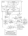
- FIG. 1 is a high-level schematic block diagram of an exemplary MRI system embodiment adapted to acquire and process data for enhanced non-contrast MRA and/or MRV imaging of NMR nuclei in-flowing to a selected spatial region that has previously been subjected to spatially non-uniform degrees of saturation within that region;
- FIG. 2 is a schematic representation of a typical non-contrast QISS (quiescent interval single shot) MRI sequence using a modified pre-saturation pulse having a non-uniform profile in the spatial domain across the selected image slice;
- QISS fluorescent interval single shot
- FIG. 3 schematically illustrates a pre-saturation pulse profile in the spatial domain having lesser saturation near the in-flow edge of the imaged slice and greater saturation near the out-flow edge of the imaged slice;
- FIGS. 4A-4D schematically illustrate examples of a few possible pre-saturation profiles in the spatial domain across the slice to be imaged
- FIGS. 5A-5B depict simulated examples of vessel signal and relative signal improvement (as compared to a uniform conventional profile) for blood flow as a function of velocity using differently shaped pre-saturation profiles;
- FIGS. 6A-6B depict simulated vessel signal and relative signal improvement (as compared to a uniform conventional profile) as a function of slice thickness for relatively slow-flowing blood;
- FIGS. 7A-7B depict simulated vessel signal and relative signal improvement (as compared to a uniform conventional profile) as a function of the quiescent interval in a QISS MRA sequence for relatively slow-flowing blood and differently shaped pre-saturation profiles;
- FIGS. 8A-8B depict and compare actual images using (a) a conventional rectangular uniform saturation profile and (b) a ramp-shaped non-uniform saturation profile (for relatively fast-moving blood flows).
- the MRI system shown in FIG. 1 includes a gantry 10 (shown in schematic cross-section) and various related system components 20 interfaced therewith. At least the gantry 10 is typically located in a shielded room.
- One MRI system geometry depicted in FIG. 1 includes a substantially coaxial cylindrical arrangement of the static field B0 magnet 12 , a G x , G y and G z gradient coil set 14 and an RF coil assembly 16 .
- an imaging volume 18 shown as substantially encompassing the head of a patient 9 supported by a patient bed or table 11 .
- various RF coil structures and/or coil arrays may be used for transmitting and/or receiving RF signals to/from the imaging volume 18 .
- An MRI system controller 22 has input/output ports connected to display 24 , keyboard/mouse 26 and printer 28 .
- the display 24 may be of the touch-screen variety so that it provides control inputs as well.
- the MRI system controller 22 interfaces with MRI sequence controller 30 which, in turn, controls the G x , G y and G z gradient coil drivers 32 , as well as the RF transmitter 34 and the transmit/receive switch 36 (if the same RF coil is used for both transmission and reception).
- MRI sequence controller 30 controls the G x , G y and G z gradient coil drivers 32 , as well as the RF transmitter 34 and the transmit/receive switch 36 (if the same RF coil is used for both transmission and reception).
- one or more suitable physiological transducers 8 may be affixed to the patient's body to provide ECG (electrocardiogram) and/or peripheral pulsatile gating signals to the MRI sequence controller 30 .
- the MRI sequence controller 30 also has access to suitable program code structure 38 for implementing MRI data acquisition sequences already available in the repertoire of the MRI sequence controller 30 —e.g., to generate non-contrast MRA (magnetic resonance angiography) and/or MRV (magnetic resonance venography) images using operator and/or system inputs defining particular MRI data acquisition sequence parameters.
- suitable program code structure 38 for implementing MRI data acquisition sequences already available in the repertoire of the MRI sequence controller 30 —e.g., to generate non-contrast MRA (magnetic resonance angiography) and/or MRV (magnetic resonance venography) images using operator and/or system inputs defining particular MRI data acquisition sequence parameters.
- the MRI system 20 includes an RF receiver 40 providing input to data processor 42 so as to create processed image data to display 24 .
- the MRI data processor 42 is also configured for access to image reconstruction program code structure 44 and to MR (magnetic resonance) image memory 46 (e.g., for storing MR image data derived from processing in accordance with the exemplary embodiments and the image reconstruction program code structure 44 ).
- MR magnetic resonance
- FIG. 1 Also illustrated in FIG. 1 is a generalized depiction of an MRI system program/data store 50 where stored program code structures (e.g., for generation of non-uniform pre-saturation pulse profiles for enhanced non-contrast MRA and/or MRV images, for accepting operator inputs to control same, etc.) are stored in computer-readable storage media accessible to the various data processing components of the MRI system.
- the program store 50 may be segmented and directly connected, at least in part, to different ones of the system 20 processing computers having most immediate need for such stored program code structures in their normal operation (i.e., rather than being commonly stored and connected directly to the MRI system controller 22 ).
- FIG. 1 depiction is a very high-level simplified diagram of a typical MRI system with some modifications so as to practice exemplary embodiments to be described hereinbelow.
- the system components can be divided into different logical collections of “boxes” and typically comprise numerous digital signal processors (DSP), microprocessors, special purpose processing circuits (e.g., for fast A/D conversions, fast Fourier transforming, array processing, etc.).
- DSP digital signal processors
- microprocessors e.g., for fast A/D conversions, fast Fourier transforming, array processing, etc.
- Each of those processors is typically a clocked “state machine” wherein the physical data processing circuits progress from one physical state to another upon the occurrence of each clock cycle (or predetermined number of clock cycles).
- processing circuits e.g., CPUs, registers, buffers, arithmetic units, etc.
- processing circuits e.g., CPUs, registers, buffers, arithmetic units, etc.
- associated data storage media e.g., bit storage sites in magnetic storage media
- an array of computer-readable accessible data value storage sites e.g., multi-digit binary representations of pixel values
- some prior state e.g., all uniform “zero” values or all “one” values
- the physical states at the physical sites of such an array e.g., of pixel values
- minimum and maximum values e.g., the tissues of a patient over an imaged volume space
- arrays of stored data values represent and also constitute a physical structure—as does a particular structure of computer control program codes that, when sequentially loaded into instruction registers and executed by one or more CPUs of the MRI system 20 , cause a particular sequence of operational states to occur and be transitioned through within the MRI system.
- the exemplary embodiments described below provide improved ways to acquire and/or process MRI data acquisitions and/or to generate and display MR images.
- a general class of non-contrast MRA techniques generate white blood angiography images by saturating background tissue in an intended image slice region and thereafter allowing “fresh” (i.e., unsaturated) in-flowing blood to appear bright in a subsequently acquired MR image of the image slice region.
- Time-of-Flight (TOF) MRI is one example of such a technique.
- QISS Quiescent Interval Single Shot
- FIG. 2 A variant of TOF, called Quiescent Interval Single Shot (QISS) is depicted schematically in FIG. 2 .
- QISS applies a spatially selective pre-saturation pulse directly on the image slice of interest. The effect of the on-slice saturation is to immediately generate background suppression in the slice of interest.
- QI quiescent interval
- fresh non-saturated blood is allowed to flow into the slice of interest.
- the QI typically is chosen to be approximately 200-300 ms, i.e., long enough to allow sufficient in-flow of fresh blood, but short enough to prevent substantial T1 NMR recovery of the previously saturated background tissue.
- the magnetization of fresh in-flow blood is detected using conventional MRI pulse sequence(s), e.g., a 2D readout such as SSFP (steady-state free precession).
- a 2D readout such as SSFP (steady-state free precession).
- the readout is typically performed in a “single shot”.
- a single shot one or more different magnitudes of phase encoding are employed so as to acquire data during that shot for a corresponding part of k-space.
- venous blood can be saturated using a separate “walking” (i.e., sequentially moved) spatially selective pre-saturation pulse, as is commonly applied in TOF2D.
- the on-slice spatially selective pre-saturation is effective at reducing background tissue signal.
- it also saturates blood then disposed within the slice of interest.
- the QI is typically not long enough to allow complete refreshment of blood within the slice during a typical MRI data acquisition pulse sequence.
- Some residual saturated slow-flowing blood may thus still be in the slice at the time of MRI data acquisition, thereby resulting in undesirable signal loss. This same problem gets worse with thicker slices and/or a shorter QI.
- the MRI signal emanating from small vessels may be severely diminished, often to the point where it is absent in the final image.
- the signal from the edges of larger vessels is also decreased, thereby reducing their apparent lumen width and resulting in possible over-estimation of stenosis.
- the second problem is that the QI often must be carefully chosen to allow sufficient in-flow while reducing background signal. If the quiescent interval is long relative to the T1 NMR relaxation time of background tissue, undesirable background signal can increase and reduce conspicuity of the vessels to be imaged. This problem is most prevalent for fat nuclei since QI is often on the order of fat T1 (e.g., ⁇ 250 ms).
- An exemplary embodiment described below modifies the spatial profile of the pre-saturation pulse in a non-contrast MRI (e.g., MRA and/or MRV) sequence to address at least some of the above-discussed disadvantages.
- the pre-saturation spatial profile of the pulse can be “shaped” to selectively saturate to a greater degree near an “out-flow edge” of the slice of interest and selectively saturate less near the “in-flow edge” of the slice as shown in FIG. 3 .
- the pre-saturation pulse can be designed to generate a ramped spatial profile, similar to a TONE (tilt optimized non-saturated excitation) pulse or other shaped spatial profile RF excitation pulses, with minimal flip angle near the in-flow edge and maximum flip angle near the out-flow edge.
- the time domain envelope of a spatially selective RF NMR pulse is related to the spatial domain profile by a Fourier Transformation (FT).
- FT Fourier Transformation
- FT ⁇ 1 inverse Fourier Transformation
- Flowing spins starting at the arterial in-flow edge of the ⁇ z-thick image slice of interest take the longest time to exit the slice (and be replaced by fresh in-flow magnetization).
- these spins are only partially saturated (or possibly not at all).
- they can still contribute signal to the final image.
- the spins near the out-flow edge of the slice are more strongly saturated during pre-saturation. However, they have less distance to travel to exit the slice, and thus they may never contribute to the final signal anyway, regardless of the status of their magnetization.
- the acquired image signal is effectively the integral of the signal across the dimensions of each voxel.
- the signal contribution of the background tissue is effectively the integral of complex magnetization following the pre-saturation pulse (e.g., including T1 relaxation effects during the QI if QISS is used). Therefore, a spatially shaped pre-saturation pulse can be designed in such a way that its spatial profile integrates to null signal while still applying a spatially shaped pre-saturation profile across the slice.
- non-uniform pre-saturation pulses can be designed—and some are depicted in FIGS. 4B-4D .
- Some examples of non-uniform shaping include a linear ramp ( FIG. 4B ) similar to a TONE RF excitation pulse, a parabolic shape ( FIG. 4D ) similar to a VUSE (variable angle uniform signal excitation) RF excitation pulse, or a simple half-slice-width rectangular selection ( FIG. 4C ). All of these pulse profiles have the same integrated area. The pulses themselves have been well understood for some time as RF excitation pulses (i.e., an initial NMR excitation part of an MRI data acquisition sequence).
- spatially shaped profile RF pulses as spatially selective pre-saturation RF pulses (e.g., for the purpose of non-contrast in-flow MRA) has now been discovered as a new way to take advantage of their spatially non-uniform shaped selection profiles.
- saturation is used to confer signal suppression, especially of initial positive magnetization (Mz) in the subsequent image.
- the spatial pre-saturation pulse is not restricted to a 90° nutation.
- the spatial pre-saturation pulse will likely include spatial regions where the nutation exceeds 90°.
- the effect of the saturation in spatial regions is greater than a 90° nutation, it is still described as saturation as opposed to using the term “inversion.”
- a spatial pre-pulse locally has a greater nutation angle, even if that angle exceeds 90°, in these exemplary embodiments, such is described as “greater saturation” compared to lesser RF nutation, even if that lesser nutation is closer to a 90° nutation.
- Such usage is common in MRI where spatial pulses, chemically selective pre-pulses or the like may often be utilized with nutation angles greater than 90° to accomplish saturation effects within a more complicated pulse sequence.
- the non-uniformly shaped pre-saturation pulse greatly increases MRI signal contribution from relatively slow velocity blood as shown in FIGS. 5A-5B .
- the simulated signal increase is generally between 20-60%, depending on blood velocity, QI and slice thickness.
- fast velocity blood e.g., peak velocity >10 cm/s
- non-uniformly shaped pre-saturation profiles may offer no relative improvement as almost all of the blood has been refreshed during QI.
- a QISS data acquisition scan (as depicted schematically in FIG. 2 ) can become less sensitive to the choice of critical parameters such as slice thickness and QI.
- the slice of interest may be thickened to increase SNR and/or save scan time as depicted in FIGS. 6A-6B .
- non-uniformly shaped pre-saturation pulses relieve the burden of QI selection and also generate more robust signals, even for slow-flowing spins, across a wide range of QI as depicted in FIGS. 7A-7B .
- a non-uniformly shaped pre-saturation pulse can make the vessel signal largely independent of blood velocity (e.g., see FIGS. 5A-5B ).
- a QISS data acquisition scan can become less sensitive to cardiac phase—and it may become less necessary to scan during the period of fastest arterial blood flow.
- By relaxing dependence on cardiac timing it may even be possible to execute a QISS data acquisition scan ungated, thus further saving scan time and lessening set-up complication.
- a QISS sequence was implemented on a research 3 T scanner.
- the arterial trifurcation area was examined on a healthy volunteer using (a) a conventional uniformly shaped rectangular-profile pre-saturation pulse, and then (b) a non-uniform ramp-shaped pulse.
- the ramp-shaped pulse had a minimum flip angle of 45° on the in-flow edge and a maximum flip angle of 135° on the out-flow edge.
- FIGS. 8A and 8B compare conventional uniform rectangular saturation profile (left) vs. ramp shaped pre-saturation profile (right) for relatively fast flow arteries (the trifurcation) where major improvement for extremely slow blood flows was not expected.
- the images are coronal plane MIP's of QISS multi-slice data. An illustration of the saturation profile shape is given on each image (the slice thickness is exaggerated for demonstration purposes). The slice direction is indicated by the arrow.
- the mode of operation for exemplary embodiments is simple.
- the spatial pre-saturation pulse shape which is typically a conventional uniform rectangular shaped profile, is replaced with a non-uniformly shaped spatial profile pre-saturation pulse.
- the non-uniform profile shape can be arbitrarily defined, and thus can be designed to maximize MRI signal from in-flowing nuclei based on parameters such as flow velocity, slice thickness and in-flow time (QI).
- QI flow velocity
- FIGS. 4B-4D Some suggested non-uniform saturation profiles are diagrammed in FIGS. 4B-4D .
- the detailed design of such slice pre-saturation profiles can be generated using a number of well-known methods.
- the average flip angle of the saturation profile is a free parameter.
- a flip angle of 90° has an advantage in being robust with respect to gating variations (i.e., R-R interval fluctuations in EKG signal due to arrhythmia).
- Various MRA and/or MRV pulse sequences are already established.
- using a non-uniform pre-saturation spatial profile should offer improvement—e.g., such as for a critical aspect of the QISS technique like the pre-saturation RF pulse and its associated in-flow period.
- the pre-saturation profile shape may also be adjusted (e.g., reversed) to selectively enhance fast-flowing spins.
- the exemplary non-uniformly shaped pre-saturation profile techniques can increase signal from slow-flowing spins (e.g., velocity ⁇ 10 cm/s). By this same mechanism, the shaped pre-saturation profile better maintains vessel signal for short post-saturation delays (QI) or thick slices. Since the non-uniformly shaped pre-saturation profile makes QISS less sensitive to flow velocity, the QISS application becomes more robust to variations in flow velocity, including arrhythmia.
- the spatially non-uniform flip angle of the pre-saturation pulse can result in greater specific absorption rate (SAR) (e.g., because SAR is proportional to the square of the flip angle, the SAR of a non-uniform profile will be greater than a uniform rectangular shaped pulse), the SAR contribution of the pre-saturation pulse is only a fraction of the overall SAR of a complete sequence (which is dominated by the RF excitation pulse).
- SAR specific absorption rate
- the non-uniform flip angle profile of the shaped pre-saturation pulse can produce non-uniform saturation. Since the total saturation of the slice is the integral of NMR magnetization across the slice, depending on the delay time (QI), a non-uniform flip angle applied to heterogeneous T1 can possibly produce greater background signal than a uniform flip angle applied to heterogeneous T1. However, since the slices are typically thin ( ⁇ 5 mm) and the adjacent tissue generally homogeneous (fat or muscle), this is a negligible issue, as demonstrated by FIGS. 8A-8B .
- the exemplary embodiments use a shaped profile selection pulse as a pre-saturation pulse. Modifying the saturation profile selectively enhances velocity-dependent signal from in-flowing spins.
Landscapes
- Physics & Mathematics (AREA)
- Health & Medical Sciences (AREA)
- Nuclear Medicine, Radiotherapy & Molecular Imaging (AREA)
- Signal Processing (AREA)
- Radiology & Medical Imaging (AREA)
- Engineering & Computer Science (AREA)
- General Health & Medical Sciences (AREA)
- High Energy & Nuclear Physics (AREA)
- Condensed Matter Physics & Semiconductors (AREA)
- General Physics & Mathematics (AREA)
- Vascular Medicine (AREA)
- Magnetic Resonance Imaging Apparatus (AREA)
- Measurement And Recording Of Electrical Phenomena And Electrical Characteristics Of The Living Body (AREA)
Abstract
Description
Claims (19)
Priority Applications (4)
| Application Number | Priority Date | Filing Date | Title |
|---|---|---|---|
| US13/112,349 US8854041B2 (en) | 2011-05-20 | 2011-05-20 | Spatially shaped pre-saturation profile for enhanced non-contrast MRA |
| JP2012097123A JP5931559B2 (en) | 2011-05-20 | 2012-04-20 | Apparatus and method for magnetic resonance imaging |
| CN201210156540.XA CN102783949B (en) | 2011-05-20 | 2012-05-18 | Magnetic resonance imaging device and method |
| EP12168563.0A EP2525233B1 (en) | 2011-05-20 | 2012-05-18 | Spatially non-uniform presaturation of the imaging region in time-of-flight magnetic resonance angiography |
Applications Claiming Priority (1)
| Application Number | Priority Date | Filing Date | Title |
|---|---|---|---|
| US13/112,349 US8854041B2 (en) | 2011-05-20 | 2011-05-20 | Spatially shaped pre-saturation profile for enhanced non-contrast MRA |
Publications (2)
| Publication Number | Publication Date |
|---|---|
| US20120293172A1 US20120293172A1 (en) | 2012-11-22 |
| US8854041B2 true US8854041B2 (en) | 2014-10-07 |
Family
ID=47174468
Family Applications (1)
| Application Number | Title | Priority Date | Filing Date |
|---|---|---|---|
| US13/112,349 Active 2032-05-17 US8854041B2 (en) | 2011-05-20 | 2011-05-20 | Spatially shaped pre-saturation profile for enhanced non-contrast MRA |
Country Status (2)
| Country | Link |
|---|---|
| US (1) | US8854041B2 (en) |
| JP (1) | JP5931559B2 (en) |
Cited By (1)
| Publication number | Priority date | Publication date | Assignee | Title |
|---|---|---|---|---|
| US10520572B2 (en) | 2014-12-25 | 2019-12-31 | General Electric Company | Magnetic resonance apparatus |
Families Citing this family (5)
| Publication number | Priority date | Publication date | Assignee | Title |
|---|---|---|---|---|
| DE102013201814B4 (en) * | 2013-02-05 | 2018-11-08 | Siemens Healthcare Gmbh | Method for magnetic resonance imaging with multidimensional, location-selective RF pulses in an outdoor area |
| DE102013214867B4 (en) | 2013-07-30 | 2015-02-12 | Siemens Aktiengesellschaft | Determining a magnetic resonance drive sequence with concentric, circular transmission trajectories |
| US9498139B2 (en) * | 2014-02-03 | 2016-11-22 | Toshiba Medical Systems Corporation | Background suppression by time dependent flip angle of saturation pulses |
| KR101995904B1 (en) * | 2018-11-09 | 2019-07-04 | 한국기초과학지원연구원 | Method for measuring spatial magnetic field distribution of magnet and apparatus for measuring spatial magnetic field distribution of magnet using it |
| WO2020198631A1 (en) * | 2019-03-27 | 2020-10-01 | The General Hospital Corporation | Multi-shot echo planar imaging using reordered segments and recursive radio frequency pulse design giving matched slice profiles across segments |
Citations (13)
| Publication number | Priority date | Publication date | Assignee | Title |
|---|---|---|---|---|
| US20030160611A1 (en) | 2002-02-25 | 2003-08-28 | Mitsuharu Miyoshi | MRI apparatus and MRA imaging method |
| US20030166999A1 (en) * | 2001-07-18 | 2003-09-04 | Marconi Medical Systems, Inc. | Automatic vessel identification for angiographic screening |
| US6889072B2 (en) * | 1993-06-07 | 2005-05-03 | Martin R. Prince | Method and apparatus for administration of contrast agents for use in magnetic resonance arteriography |
| US7020314B1 (en) * | 2001-11-13 | 2006-03-28 | Koninklijke Philips Electronics N.V. | Black blood angiography method and apparatus |
| WO2009015348A1 (en) | 2007-07-25 | 2009-01-29 | The Board Of Trustees Of The University Of Illinois | System and method for providing flow-enhanced signal intensity during a functional mri process |
| US7680527B2 (en) * | 1993-06-07 | 2010-03-16 | Prince Martin R | Method and apparatus for imaging abdominal aorta and aortic aneurysms |
| US20100134103A1 (en) * | 2008-07-25 | 2010-06-03 | Edelman Robert R | System and Method For Ghost Magnetic Resonance Imaging |
| US20100201361A1 (en) * | 2007-05-03 | 2010-08-12 | Edelman Robert R | System and method for passive catheter tracking with magnetic resonance imaging |
| US20100226556A1 (en) * | 2007-11-16 | 2010-09-09 | Hitachi Medical Corporation | Magnetic Resonance Imaging Apparatus and Blood Vessel Imaging Method |
| US20100268062A1 (en) | 2009-04-16 | 2010-10-21 | Edelman Robert R | Method for non-contrast enhanced magnetic resonance angiography |
| US8332010B2 (en) * | 2009-04-16 | 2012-12-11 | Ghost Medical Technologies, Ltd | Method for non-contrast enhanced magnetic resonance angiography |
| US8401258B2 (en) * | 2007-03-16 | 2013-03-19 | Sti Medical Systems, Llc | Method to provide automated quality feedback to imaging devices to achieve standardized imaging data |
| US20130317348A1 (en) * | 2012-05-24 | 2013-11-28 | Toshiba Medical Systems Corporation | Semi-automated non-contrast magnetic resonance angiography (mra) |
Family Cites Families (4)
| Publication number | Priority date | Publication date | Assignee | Title |
|---|---|---|---|---|
| US5307014A (en) * | 1991-10-18 | 1994-04-26 | Siemens Medical Systems, Inc. | Inflow MR angiography with spatially variable flip angles |
| JPH05154132A (en) * | 1991-11-30 | 1993-06-22 | Shimadzu Corp | MR imaging |
| JP4594482B2 (en) * | 2000-03-14 | 2010-12-08 | 株式会社東芝 | Magnetic resonance imaging method and magnetic resonance imaging apparatus |
| JP5361234B2 (en) * | 2007-04-25 | 2013-12-04 | 株式会社東芝 | Magnetic resonance imaging system |
-
2011
- 2011-05-20 US US13/112,349 patent/US8854041B2/en active Active
-
2012
- 2012-04-20 JP JP2012097123A patent/JP5931559B2/en active Active
Patent Citations (17)
| Publication number | Priority date | Publication date | Assignee | Title |
|---|---|---|---|---|
| US6889072B2 (en) * | 1993-06-07 | 2005-05-03 | Martin R. Prince | Method and apparatus for administration of contrast agents for use in magnetic resonance arteriography |
| US7680527B2 (en) * | 1993-06-07 | 2010-03-16 | Prince Martin R | Method and apparatus for imaging abdominal aorta and aortic aneurysms |
| US6845260B2 (en) * | 2001-07-18 | 2005-01-18 | Koninklijke Philips Electronics N.V. | Automatic vessel indentification for angiographic screening |
| US20030166999A1 (en) * | 2001-07-18 | 2003-09-04 | Marconi Medical Systems, Inc. | Automatic vessel identification for angiographic screening |
| US7020314B1 (en) * | 2001-11-13 | 2006-03-28 | Koninklijke Philips Electronics N.V. | Black blood angiography method and apparatus |
| US20030160611A1 (en) | 2002-02-25 | 2003-08-28 | Mitsuharu Miyoshi | MRI apparatus and MRA imaging method |
| CN1441258A (en) | 2002-02-25 | 2003-09-10 | Ge医疗系统环球技术有限公司 | MRI device and MRA imaging method |
| US6814280B2 (en) * | 2002-02-25 | 2004-11-09 | Ge Medical Systems Global Technology Company, Llc | MRI apparatus and MRA imaging method |
| US8401258B2 (en) * | 2007-03-16 | 2013-03-19 | Sti Medical Systems, Llc | Method to provide automated quality feedback to imaging devices to achieve standardized imaging data |
| US20100201361A1 (en) * | 2007-05-03 | 2010-08-12 | Edelman Robert R | System and method for passive catheter tracking with magnetic resonance imaging |
| WO2009015348A1 (en) | 2007-07-25 | 2009-01-29 | The Board Of Trustees Of The University Of Illinois | System and method for providing flow-enhanced signal intensity during a functional mri process |
| US20100226556A1 (en) * | 2007-11-16 | 2010-09-09 | Hitachi Medical Corporation | Magnetic Resonance Imaging Apparatus and Blood Vessel Imaging Method |
| US20100134103A1 (en) * | 2008-07-25 | 2010-06-03 | Edelman Robert R | System and Method For Ghost Magnetic Resonance Imaging |
| US8154287B2 (en) * | 2008-07-25 | 2012-04-10 | Northshore University Healthsystem | System and method for ghost magnetic resonance imaging |
| US8332010B2 (en) * | 2009-04-16 | 2012-12-11 | Ghost Medical Technologies, Ltd | Method for non-contrast enhanced magnetic resonance angiography |
| US20100268062A1 (en) | 2009-04-16 | 2010-10-21 | Edelman Robert R | Method for non-contrast enhanced magnetic resonance angiography |
| US20130317348A1 (en) * | 2012-05-24 | 2013-11-28 | Toshiba Medical Systems Corporation | Semi-automated non-contrast magnetic resonance angiography (mra) |
Non-Patent Citations (16)
| Title |
|---|
| Edelman R.R. et al., "Quantification of Blood Flow with Dynamic MR Imaging and Presaturation Bolus Tracking," Radiology, Radiological Society of North America, Oak Brook, IL, US; vol. 171, Jan. 1, 1989, pp. 551-556, XP002481393, ISSN: 0033-8419. |
| Edelman, et al., "Quiescent Interval Single Shot MR Angiography," Proceedings of the Annual Scientific Meeting and Exhibition of the International Society for Magnetic Resonance in Medicine, Stockholm, Sweden, p. 1384 (2010). |
| Edelman, et al., "Quiescent-Interval Single-Shot Unenhanced Magnetic Resonance Angiography of Peripheral Vascular Disease: Technical Considerations and Clinical Feasibility," Mag. Res. Med., vol. 63, pp. 951-958 (2010). |
| Extended European search report in EP 12168563.0-2216 dated Aug. 14, 2012. |
| Glielmi, et al., "Navigator-Gated Quiescent Interval Single Shot for Pelvic MR Angiography," Proceedings of the Annual Scientific Meeting and Exhibition of the International Society for Magnetic Resonance in Medicine, Stockholm, Sweden, p. 1398 (2010). |
| Hodnett, et al., "Clinical Evaluation of Peripheral Vascular Disease Using a Hybrid Approach: Unenhanced Quiescent Interval Single Shot and Low-Dose Twist MR Angiography," Proceedings of the Annual Scientific Meeting and Exhibition of the International Society for Magnetic Resonance in Medicine, Stockholm, Sweden, p. 1408 (2010). |
| Hodnett, et al., "Combined Renal and Peripheral MRA with a New Technique at 3.0 T," Proceedings of the Annual Scientific Meeting and Exhibition of the International Society for Magnetic Resonance in Medicine, Stockholm, Sweden, p. 1408 (2010). |
| K.J. Jung et al., "Artifacts due to Reverse Flow in the Artery and Their Correction in TOF Angiography with Presaturation of the Vein," Proc. Intl. Soc. Mag. Reson. Med., Jan. 1, 2000, p. 1826, XP55034598. |
| Nägele, et al., "The Effects of Linearly Increasing Flip Angles on 3D Inflow MR Angiography," Mag. Res. Med., vol. 31, pp. 561-566 (1994). |
| Offerman, et al., "Unenhanced Techniques for Peripheral MRA: Phantom Evaluation in the Setting of Triphasic Flow and Stenosis," Proceedings of the Annual Scientific Meeting and Exhibition of the International Society for Magnetic Resonance in Medicine, Stockholm, Sweden, p. 1413 (2010). |
| Office Action dated Feb. 18, 2014 in CN 201210156540.X. |
| Priatna, et al., "Variable-Angle Uniform Signal Excitation (VUSE) for Three-Dimensional Time-of-Flight MR Angiography," J. Med. Res. Imaging, vol. 5, No. 4, pp. 421-427 (1995). |
| Purdy, et al. "The Design of Variable Tip Angle Slab Selection (TONE) Pulses for Improved 3-D MR Angiography," Proceedings of the Annual Scientific Meeting and Exhibition of the International Society for Magnetic Resonance in Medicine, Berlin, Germany, p. 882 (1992). |
| Tetsuya Matsuda et al., "An Asymmetric Slice Profile: Spatial Alteration of Flow Signal Response in 3D Time-of-Flight NMR Angiography," Magnetic Resonance in Medicine, Academic Press, Duluth, MN, US, vol. 29, No. 6, Jun. 1, 1993, pp. 783-789, XP00036962, ISSN: 0740-3194. |
| Tyszka M. et al., "Automatic Analysis of Tagged Images of Laminar Fluid Flow," Journal of Magnetic Resonance, Academic Press, Orlando, FL, US, vol. 97, No. 2, Apr. 1, 1992, pp. 391-397, XP000275064, ISSN: 1090-7807. |
| Yu Liu et al., "Magnetization-Prepared Cardiac Imaging Using Gradient Echo Acquisition," Magnetic Resonance in Medicine, Academic Press, Duluth, MN, US, vol. 30, No. 2, Aug. 1, 1993, pp. 271-275, XP000385362, ISSN: 0740-3194. |
Cited By (1)
| Publication number | Priority date | Publication date | Assignee | Title |
|---|---|---|---|---|
| US10520572B2 (en) | 2014-12-25 | 2019-12-31 | General Electric Company | Magnetic resonance apparatus |
Also Published As
| Publication number | Publication date |
|---|---|
| US20120293172A1 (en) | 2012-11-22 |
| JP2012239884A (en) | 2012-12-10 |
| JP5931559B2 (en) | 2016-06-08 |
Similar Documents
| Publication | Publication Date | Title |
|---|---|---|
| US8076934B2 (en) | Black-blood steady-state free precession magnetic resonance imaging | |
| Zhang et al. | Magnetic resonance imaging in real time: advances using radial FLASH | |
| US9983286B2 (en) | SAR reduction in fast advanced spin echo (FASE) or single-shot fast spin echo (SS-FSE) imaging | |
| JP5325795B2 (en) | Contrast-enhanced MRA using highly constrained backprojection reconstruction method using phase difference composite image | |
| US8332010B2 (en) | Method for non-contrast enhanced magnetic resonance angiography | |
| Koktzoglou et al. | Radial fast interrupted steady‐state (FISS) magnetic resonance imaging | |
| US20100268062A1 (en) | Method for non-contrast enhanced magnetic resonance angiography | |
| US9788761B2 (en) | Motion correction for magnetic resonance angiography (MRA) with 3D radial acquisitions | |
| Nielsen et al. | Functional perfusion imaging using pseudocontinuous arterial spin labeling with low‐flip‐angle segmented 3D spiral readouts | |
| EP2525233B1 (en) | Spatially non-uniform presaturation of the imaging region in time-of-flight magnetic resonance angiography | |
| US8299788B2 (en) | MRI using hybrid image | |
| US20120293172A1 (en) | Spatially shaped pre-saturation profile for enhanced non-contrast mra | |
| US8760161B2 (en) | System and method for enhanced contrast MR imaging | |
| JP2017221664A (en) | Magnetic resonance imaging device | |
| JP6529774B2 (en) | Magnetic resonance imaging apparatus and magnetic resonance imaging method | |
| US9720064B2 (en) | Variable TR (vTR) function in fresh blood imaging (FBI) | |
| Kozerke et al. | Reduced data acquisition methods in cardiac imaging | |
| US9414765B2 (en) | Fresh blood imaging (FBI) with independently controlled MRI data acquisition parameters for diastolic and systolic MRI acquisition sub-sequences | |
| US20230003817A1 (en) | Magnetic resonance imaging apparatus | |
| US20160338600A1 (en) | Method For Non-Contrast Enhanced Magnetic Resonance Angiography | |
| Wendell et al. | Cardiac cine imaging | |
| Jin et al. | Spatial, Temporal resolution and signal-to-noise ratio | |
| Pocci | Analysis of Cartesian and projection (k, t)-space sampling patterns when using the partially separable functions model for cardiac perfusion MR imaging | |
| HK1138069B (en) | Contrast enhanced mra with highly constrained backprojection reconstruction using phase contrast composite image | |
| HK1124666A1 (en) | Constrained backprojection reconstruction method for undersampled mri |
Legal Events
| Date | Code | Title | Description |
|---|---|---|---|
| AS | Assignment |
Owner name: TOSHIBA MEDICAL SYSTEMS CORPORATION, JAPAN Free format text: ASSIGNMENT OF ASSIGNORS INTEREST;ASSIGNORS:WHEATON, ANDREW J.;DANNELS, WAYNE R.;REEL/FRAME:026315/0723 Effective date: 20110520 Owner name: KABUSHIKI KAISHA TOSHIBA, JAPAN Free format text: ASSIGNMENT OF ASSIGNORS INTEREST;ASSIGNORS:WHEATON, ANDREW J.;DANNELS, WAYNE R.;REEL/FRAME:026315/0723 Effective date: 20110520 |
|
| STCF | Information on status: patent grant |
Free format text: PATENTED CASE |
|
| AS | Assignment |
Owner name: TOSHIBA MEDICAL SYSTEMS CORPORATION, JAPAN Free format text: ASSIGNMENT OF ASSIGNORS INTEREST;ASSIGNOR:KABUSHIKI KAISHA TOSHIBA;REEL/FRAME:038891/0693 Effective date: 20160316 |
|
| MAFP | Maintenance fee payment |
Free format text: PAYMENT OF MAINTENANCE FEE, 4TH YEAR, LARGE ENTITY (ORIGINAL EVENT CODE: M1551) Year of fee payment: 4 |
|
| MAFP | Maintenance fee payment |
Free format text: PAYMENT OF MAINTENANCE FEE, 8TH YEAR, LARGE ENTITY (ORIGINAL EVENT CODE: M1552); ENTITY STATUS OF PATENT OWNER: LARGE ENTITY Year of fee payment: 8 |
|
| FEPP | Fee payment procedure |
Free format text: MAINTENANCE FEE REMINDER MAILED (ORIGINAL EVENT CODE: REM.); ENTITY STATUS OF PATENT OWNER: LARGE ENTITY |