US8852773B2 - Battery pack - Google Patents
Battery pack Download PDFInfo
- Publication number
- US8852773B2 US8852773B2 US13/421,482 US201213421482A US8852773B2 US 8852773 B2 US8852773 B2 US 8852773B2 US 201213421482 A US201213421482 A US 201213421482A US 8852773 B2 US8852773 B2 US 8852773B2
- Authority
- US
- United States
- Prior art keywords
- battery pack
- junction box
- housing
- coolant
- sleeve
- Prior art date
- Legal status (The legal status is an assumption and is not a legal conclusion. Google has not performed a legal analysis and makes no representation as to the accuracy of the status listed.)
- Active, expires
Links
Images


Classifications
-
- H01M2/36—
-
- H—ELECTRICITY
- H01—ELECTRIC ELEMENTS
- H01M—PROCESSES OR MEANS, e.g. BATTERIES, FOR THE DIRECT CONVERSION OF CHEMICAL ENERGY INTO ELECTRICAL ENERGY
- H01M10/00—Secondary cells; Manufacture thereof
- H01M10/60—Heating or cooling; Temperature control
- H01M10/65—Means for temperature control structurally associated with the cells
- H01M10/656—Means for temperature control structurally associated with the cells characterised by the type of heat-exchange fluid
- H01M10/6567—Liquids
-
- H—ELECTRICITY
- H01—ELECTRIC ELEMENTS
- H01M—PROCESSES OR MEANS, e.g. BATTERIES, FOR THE DIRECT CONVERSION OF CHEMICAL ENERGY INTO ELECTRICAL ENERGY
- H01M10/00—Secondary cells; Manufacture thereof
- H01M10/60—Heating or cooling; Temperature control
- H01M10/65—Means for temperature control structurally associated with the cells
- H01M10/655—Solid structures for heat exchange or heat conduction
- H01M10/6551—Surfaces specially adapted for heat dissipation or radiation, e.g. fins or coatings
-
- H—ELECTRICITY
- H01—ELECTRIC ELEMENTS
- H01M—PROCESSES OR MEANS, e.g. BATTERIES, FOR THE DIRECT CONVERSION OF CHEMICAL ENERGY INTO ELECTRICAL ENERGY
- H01M10/00—Secondary cells; Manufacture thereof
- H01M10/60—Heating or cooling; Temperature control
- H01M10/61—Types of temperature control
- H01M10/617—Types of temperature control for achieving uniformity or desired distribution of temperature
-
- H01M10/50—
-
- H—ELECTRICITY
- H01—ELECTRIC ELEMENTS
- H01M—PROCESSES OR MEANS, e.g. BATTERIES, FOR THE DIRECT CONVERSION OF CHEMICAL ENERGY INTO ELECTRICAL ENERGY
- H01M10/00—Secondary cells; Manufacture thereof
- H01M10/60—Heating or cooling; Temperature control
- H01M10/65—Means for temperature control structurally associated with the cells
- H01M10/655—Solid structures for heat exchange or heat conduction
- H01M10/6556—Solid parts with flow channel passages or pipes for heat exchange
-
- H—ELECTRICITY
- H01—ELECTRIC ELEMENTS
- H01M—PROCESSES OR MEANS, e.g. BATTERIES, FOR THE DIRECT CONVERSION OF CHEMICAL ENERGY INTO ELECTRICAL ENERGY
- H01M50/00—Constructional details or processes of manufacture of the non-active parts of electrochemical cells other than fuel cells, e.g. hybrid cells
- H01M50/20—Mountings; Secondary casings or frames; Racks, modules or packs; Suspension devices; Shock absorbers; Transport or carrying devices; Holders
- H01M50/204—Racks, modules or packs for multiple batteries or multiple cells
- H01M50/207—Racks, modules or packs for multiple batteries or multiple cells characterised by their shape
- H01M50/209—Racks, modules or packs for multiple batteries or multiple cells characterised by their shape adapted for prismatic or rectangular cells
-
- H—ELECTRICITY
- H01—ELECTRIC ELEMENTS
- H01M—PROCESSES OR MEANS, e.g. BATTERIES, FOR THE DIRECT CONVERSION OF CHEMICAL ENERGY INTO ELECTRICAL ENERGY
- H01M50/00—Constructional details or processes of manufacture of the non-active parts of electrochemical cells other than fuel cells, e.g. hybrid cells
- H01M50/60—Arrangements or processes for filling or topping-up with liquids; Arrangements or processes for draining liquids from casings
- H01M50/609—Arrangements or processes for filling with liquid, e.g. electrolytes
- H01M50/627—Filling ports
-
- H—ELECTRICITY
- H01—ELECTRIC ELEMENTS
- H01M—PROCESSES OR MEANS, e.g. BATTERIES, FOR THE DIRECT CONVERSION OF CHEMICAL ENERGY INTO ELECTRICAL ENERGY
- H01M10/00—Secondary cells; Manufacture thereof
- H01M10/60—Heating or cooling; Temperature control
- H01M10/65—Means for temperature control structurally associated with the cells
- H01M10/656—Means for temperature control structurally associated with the cells characterised by the type of heat-exchange fluid
- H01M10/6561—Gases
- H01M10/6562—Gases with free flow by convection only
-
- Y—GENERAL TAGGING OF NEW TECHNOLOGICAL DEVELOPMENTS; GENERAL TAGGING OF CROSS-SECTIONAL TECHNOLOGIES SPANNING OVER SEVERAL SECTIONS OF THE IPC; TECHNICAL SUBJECTS COVERED BY FORMER USPC CROSS-REFERENCE ART COLLECTIONS [XRACs] AND DIGESTS
- Y02—TECHNOLOGIES OR APPLICATIONS FOR MITIGATION OR ADAPTATION AGAINST CLIMATE CHANGE
- Y02E—REDUCTION OF GREENHOUSE GAS [GHG] EMISSIONS, RELATED TO ENERGY GENERATION, TRANSMISSION OR DISTRIBUTION
- Y02E60/00—Enabling technologies; Technologies with a potential or indirect contribution to GHG emissions mitigation
- Y02E60/10—Energy storage using batteries
-
- Y02E60/12—
Definitions
- An aspect of the present invention relates to a battery pack capable of improving heat dissipation characteristics and reducing the temperature variation between cells.
- secondary batteries are rechargeable and can be repeatedly used.
- the secondary batteries may be implemented as a battery cell used in portable small-sized electronic devices such as a cellular phone, a desktop computer, a laptop computer, a camera and camcorder.
- the secondary batteries may be implemented as a battery pack including a plurality of battery cells, used as a power source for driving motors of a high-power hybrid electric vehicle (HEV), an electric vehicle (EV), and the like.
- HEV high-power hybrid electric vehicle
- EV electric vehicle
- junction box wires for supply electricity to various electric equipment and motor driving devices are connected through a junction box.
- Resistors, fuses, relays and the like are installed in the junction box as protection devices against overcurrent and overload.
- heat generation components such as resistors, fuses or relays generate a large amount of heat, and the heat further deteriorates battery cells close to the junction box, thereby resulting in unequal deterioration between cells in the battery pack. Accordingly, what is needed is a design for a battery pack with a structure capable of improving heat dissipation characteristics.
- Embodiments provide a battery pack capable of improving heat dissipation characteristics and reducing the temperature variation between cells.
- Embodiments also provide a battery pack in which a heat-sink structure is disposed within a junction box so as to cool heat generated from an electronic component within the junction box, thereby preventing the deterioration of battery cells.
- a battery pack including at least one battery module including a plurality of battery cells aligned in one direction, a housing that accommodates the at least one battery module and includes a coolant flow path arranged therein and a junction box arranged at a predetermined location in a vicinity of the battery module, the junction box having a sleeve arranged parallel to the coolant flow path.
- the housing may be provided with at least one inlet through which a coolant may enter the housing.
- the housing may be provided with at least one outlet through which a coolant may be discharged from the housing.
- the outlet for the housing may be the sleeve of the junction box.
- the sleeve may be arranged parallel to the outlet.
- the junction box may include at least a first sleeve and a second sleeve. The first and the second sleeves may be arranged parallel to each other and are space-apart from each other by a predetermined interval.
- the third surface may be disposed adjacent to a coolant outlet surface of the housing.
- the third surface of the junction box is spaced-apart from a vertical center line of the coolant outlet surface.
- the third surface of the junction box may be arranged at a corner of the coolant outlet surface.
- the third surface of the junction box may instead be arranged at a vertical center line of the coolant outlet surface.
- One of the second and fourth surfaces of the junction box may be arranged adjacent to a side surface of the housing that comes in contact with the coolant outlet surface.
- the second and fourth surfaces of the junction box may be arranged adjacent to respective side surfaces of the housing.
- the battery pack may include a plurality of junction boxes spaced-apart from each other by a predetermined interval.
- the junction box may include an electronic component that is in contact with an outer wall of the sleeve.
- the electronic component may be a heat generating element.
- the junction box may include a heat dissipation member arranged on an inner wall of the sleeve.
- the heat dissipation member may be a heat dissipation fin.
- the is junction box may include a plurality of heat dissipation members arranged at a predetermined interval on the inner wall of the sleeve.
- a section of the sleeve in a thickness direction may have a shape selected from a group consisting of a circle, an ellipse and a polygon.
- the battery pack may include a coolant including a fluid selected from a group consisting of a liquid and a gas.
- the sleeve may include a through-hole through which the cool
- FIG. 1A is a perspective view schematically showing a battery pack according to a first embodiment of the present invention
- FIG. 1B is a perspective view showing a junction box included in the battery pack of FIG. 1 ;
- FIG. 2 is a perspective view showing a battery module included in the battery pack according to the first embodiment of the present invention
- FIG. 3A is a perspective view schematically showing a battery pack according to a second embodiment of the present invention.
- FIG. 3B is a perspective view showing a junction box included in the battery pack of FIG. 3A ;
- FIG. 4A is a perspective view schematically showing a battery pack according to a third embodiment of the present invention.
- FIG. 4B is a perspective view showing a junction box included in the battery pack of FIG. 4A ;
- FIG. 5A is a perspective view schematically showing a battery pack according to a fourth embodiment of the present invention.
- FIG. 5B is a perspective view showing a junction box included in the battery pack of FIG. 5A .
- FIG. 1A is a perspective view schematically showing a battery pack 100 according to a first embodiment of the present invention
- FIG. 1B is a perspective view showing a junction box 120 included in the battery pack 100 of FIG. 1
- FIG. 2 is a perspective view showing a battery module 110 included in the battery pack 100 according to the first embodiment of the present invention.
- the battery pack 100 includes at least one battery module 110 having a plurality of battery cells 10 aligned in one direction, a housing 130 that accommodates the at least one battery module 110 and has a flow path of a coolant formed therein and a junction box 120 having a sleeve 127 disposed parallel to the flow path.
- the housing 130 may accommodate the at least one battery module 110 , and a plurality of battery modules 110 may be aligned so that side surfaces of the battery cells 10 are opposite to each other.
- the six surfaces of the housing 130 are defined by a housing bottom surface 136 adjacent to a bottom surface 126 of the junction box 120 , a housing top surface 135 opposite to the housing bottom surface 136 , a coolant inlet surface 131 having an inlet 137 formed thereon, a coolant outlet surface 133 having an outlet 138 formed thereon, a first housing side surface 132 simultaneously positioned between the coolant inlet surface 131 and the coolant outlet surface 133 and between the housing bottom surface 136 and the housing top surface 135 , and a second housing side surface 134 opposite to the first housing side surface 132 .
- the coolant that cools the battery cells 10 is injected into the battery pack 100 through the inlet 137 formed on the coolant inlet surface 131 of the housing 130 . Subsequently, the coolant passes through neighboring spaces of the battery cells 10 and spaces respectively formed between the battery cells 10 by barriers 115 , and is then discharged to the exterior of the battery pack 100 through the outlet 138 formed on the coolant outlet surface 133 of the housing 130 .
- the flow path of the coolant which is configured as the inlet 137 , the neighboring spaces of the battery cells 10 , the spaces between the battery cells 10 and the outlet 138 , is formed within the housing 130 .
- the housing 130 is provided with the inlet 137 through which the coolant enters the housing 130 and the outlet 138 through which the coolant is discharged from the housing 130 .
- the junction box 120 having the sleeve 127 is provided between the battery module 110 and the coolant outlet surface 133 of the housing 130 .
- the sleeve 127 is formed parallel to the flow path of the coolant.
- On the inside of sleeve 127 is a through-hole or a passageway through which the coolant may flow.
- the six surfaces of the junction box 120 is defined by the bottom surface 126 adjacent to the housing bottom surface 136 , a top surface 125 opposite to the bottom surface 126 , a first surface 121 adjacent to the battery module 110 , and second, third, fourth surfaces 122 , 123 and 124 disposed clockwise with respect to the first surface 121 .
- the third surface 123 positioned closest to the housing 130 among the surfaces of the junction box 120 of FIG. 1 is disposed adjacent to the coolant outlet surface 133 of the housing 130 .
- Coolant that passes through sleeve 127 of junction box 120 also passes through a corresponding hole in the coolant outlet surface 133 so that the coolant that passes through the junction box 120 can be immediately expelled from housing 130 of battery pack 100 .
- sleeve 127 can serve as a coolant outlet for the battery pack 100 .
- the junction box 120 may be disposed so that the center of the third surface 123 corresponds to that of the coolant outlet surface 133 of the housing 130 . That is, the junction box 120 may be disposed at the center of the coolant outlet surface 133 of the housing 130 so that a vertical center line of the junction box 120 lines up with a vertical center line of the coolant outlet surface 133 of housing 130 .
- An electronic component 129 is provided within the junction box 120 .
- the electronic component 129 is disposed to come in contact with an outer wall 127 ow of the sleeve 127 .
- a heat dissipation member 128 formed in the shape of a heat dissipation fin is provided to an inner wall 127 iw of the sleeve 127 .
- the heat dissipation member 128 is provided with a plurality of heat dissipation members and the plurality of heat dissipation members are disposed at a predetermined interval on the inner wall 127 iw of the sleeve 127 .
- the electronic component 129 is a heat generating component that generates a large amount of heat, such as a resistor, fuse or relay, which is a protection element against overcurrent and overload.
- the heat generated by the electronic component as described above may deteriorate the battery cells 10 and cause a non-uniform temperature distribution among the battery cells 10 within housing 130 .
- the heat dissipation member 128 is disposed on the inner wall 127 iw of the sleeve 127 , which comes in contact with the electronic component 129 of the junction box 120 , so that the electronic component 129 can be easily cooled. Since the coolant flows through the sleeve 127 while coming in contact with the inner wall 127 iw of the sleeve 127 , the heat dissipation efficiency of the heat dissipation member 128 can be more improved. Further, the sleeve 127 is formed in the junction box 120 , so that it is possible to reduce a pressure drop generated because the flow of the coolant is conventionally slowed down by the front of the junction box. Thus, the heat dissipation efficiency can be more improved, and the temperature variation between the battery cells can be decreased.
- the section of the sleeve 127 in the thickness direction may have various shapes such as a circular shape, an elliptic shape or a polygonal shape.
- the heat dissipation fin has been described as an example of the shape of the heat dissipation member 128 , the heat dissipation member 128 is not limited thereto. Although it has been described as an example that the heat dissipation member 128 is formed at a portion of the inner walls 127 iw of the sleeve 127 , the heat dissipation member 128 may instead be formed on the whole of the inner walls 127 iw . Meanwhile, a fluid, such as a liquid or gas may be used as the coolant.
- the battery module 110 accommodated within the housing 130 will be described with reference to FIG. 2 .
- the battery module 110 includes a plurality of battery cells 10 aligned in one direction, and each of the battery cells is provided with positive and negative electrode terminals 11 and 12 .
- the battery cells 10 are aligned so that wide surfaces of adjacent battery s cells 10 are facing each other.
- Each of the battery cells 10 that constitute the battery module 110 may be manufactured by accommodating an electrode assembly and an electrolyte into a battery case and then sealing the battery case in which the electrolyte and the electrode assembly is accommodated using a cap plate 14 .
- the electrode assembly includes a positive electrode plate, a negative electrode plate and a separator interposed between the electrode plates.
- the cap plate 14 may be provided in the state that the positive electrode terminal 11 connected to the positive electrode plate and the negative electrode terminal 12 connected to the negative electrode plate are protruded to the exterior thereof.
- the positive and negative electrode plates generate electrochemical energy through a reaction between the electrolyte and the positive and negative electrode plates, and the generated energy is transferred to the exterior of the battery cell 10 through the positive and negative electrode terminals 11 and 12 .
- a vent 13 is provided between the positive and negative electrode terminals 11 and 12 to serve as a path through which gas can be expelled to the exterior of the battery cell 10 .
- the battery cell 10 will be described as a prismatic lithium ion secondary battery, however the present invention is not limited thereto as various other types of batteries such as a lithium polymer battery and a cylindrical battery can instead be used.
- the battery module 110 may include a plurality of battery cells 10 , a pair of first and second end plates 111 and 112 provided to be spatially spaced apart from each other, and connection members 113 and 114 that connect the first and second end plates 111 and 112 to each other.
- the first and second end plates 111 and 112 are disposed to come in surface contact with the outermost battery cells 10 , respectively, to apply pressure toward insides of the plurality of battery cells 10 .
- the connection members 113 and 114 connect the first and second end plates 111 and 112 to each other. One end of each of the connection members 113 and 114 are fastened to the first end plate 111 , and the other end of each of the connection members 113 and 114 are fastened to the second end plate 112 .
- the first and second end plates 111 and 112 may be fastened to the connection members 113 and 114 by members such as bolts and nuts.
- connection members 113 and 114 provide a space in which the plurality of battery cells 10 are aligned by connecting the first and second end plates 111 and 112 to each other, and simultaneously support both side surfaces and a bottom surface of each of the battery modules 110 .
- the connection members 113 and 114 are provided with two side connection members 113 that respectively support both side surfaces of the battery module 110 and one bottom connection member 114 that supports the bottom surface of the battery module 110 , however the locations and shapes of the connection members 113 and 114 may be variously modified according to the design of the battery module 110 .
- the battery cells 10 are fixed in the space defined by the first and second end plates 111 and 112 , the side connection members 113 and the bottom connection member 114 so as not to be easily moved by an external impact.
- the positive and negative electrode terminals 11 and 12 of two adjacent battery cells 10 may be electrically connected to each other through a bus-bar 15 .
- the bus-bar 15 is provided with holes through which the positive and negative electrode terminals 11 and 12 can pass, respectively.
- the bus-bar 15 to which the terminals are connected by passing through the holes, may be fixed by members such as nuts 16 .
- the barrier 115 may be interposed between adjacent battery cells 10 .
- a spacer (not shown) is provided to the barrier 115 .
- the barrier 115 allows the battery cells 10 to be spaced apart from each other and form a space between neighboring battery cells 10 , thereby providing a flow path for the coolant that cools the battery cells 10 .
- the coolant flows into the space provided by the barrier 115 between the battery cell 10 and exchanges heat with the battery cells 10 by coming in contact with the wide surfaces of the battery cells 10 . Then, the coolant is discharged in a direction similar to that in which the coolant flows.
- FIG. 3A is a perspective view schematically showing a battery pack 200 according to a second embodiment of the present invention
- FIG. 3B is a perspective view showing a junction box 220 included in the battery pack 200 of FIG. 3A .
- the battery pack 200 according to the second embodiment of the present invention is different from the battery pack 100 according to the first embodiment in regards to the location in which a junction box 220 is disposed.
- differences from the first embodiment will be mainly described, and overlapping descriptions will be omitted.
- the six surfaces of the housing 230 are defined by a housing bottom surface 236 adjacent to a bottom surface 226 of the junction box 220 , a housing top surface 235 opposite to the housing bottom surface 236 , a coolant inlet surface 231 having an inlet 237 formed thereon, a coolant outlet surface 233 having an outlet 238 formed thereon, a first housing side surface 232 simultaneously positioned between the coolant inlet surface 231 and the coolant outlet surface 233 and between the housing bottom surface 236 and the housing top surface 235 , and a second housing side surface 234 opposite to the first housing side surface 232 .
- the six surfaces of the junction box 220 are defined by the bottom surface 226 adjacent to the housing bottom surface 236 , a top surface 225 opposite to the bottom surface 226 , a first surface 221 adjacent to battery modules 210 , and second, third, fourth surfaces 222 , 223 and 224 disposed clockwise with respect to the first surface 221 .
- the third surface 223 is disposed facing the coolant outlet surface 233 of the housing 230
- the second surface 222 is disposed facing the first housing side surface 232 .
- the second surface 222 of the junction box 220 may be disposed opposite from the second housing side surface 234 .
- the center of the third surface 223 may be arranged at one side of and be spaced-apart from a is vertical center line of coolant outlet surface 233 of housing 230 . That is, the junction box 220 may not disposed at the center of the coolant outlet surface 233 of the housing 230 and by may instead be disposed at a corner of the coolant outlet surface 233 of the housing 230 .
- an outlet 238 according to the second embodiment of the present invention is disposed at a side of the coolant outlet surface 233 on which the junction box 220 is not disposed.
- An electronic component 229 is provided within the junction box 220 .
- the electronic component 229 is disposed to come in contact with an outer wall 227 ow of the sleeve 227 .
- a heat dissipation member 228 formed in the shape of a heat dissipation fin is provided on an inner wall 227 iw of the sleeve 227 .
- the heat dissipation member 228 may actually be a plurality of heat dissipation members disposed at a predetermined interval on the inner wall 227 iw of the sleeve 227 .
- the electronic component 229 is a heat generating component that generates a large amount of heat, such as a resistor, fuse or relay, which is a protection element against overcurrent and overload.
- the heat generated as described above may deteriorate battery cells 20 and cause the battery cells 20 to have a non-uniform heat distribution.
- the heat dissipation member 228 is disposed on the inner wall 227 iw of the sleeve 227 that is in contact with the electronic component 229 of the junction box 220 , so that the electronic component 229 can be easily cooled. Since the coolant flows within the sleeve 227 while coming in contact with the inner wall 227 iw of the sleeve 227 , is the heat dissipation efficiency of the heat dissipation member 228 can be more improved. Further, the sleeve 227 is formed in the junction box 220 , so that it is possible to reduce a pressure drop generated due to the coolant being conventionally slowed down by the front of the junction box. Thus, the heat dissipation efficiency can be more improved, and the temperature variation between the battery cells 20 can be decreased.
- FIG. 4A is a perspective view schematically showing a battery pack 300 according to a third embodiment of the present invention
- FIG. 4B is a perspective view showing a junction box 320 included within the battery pack 300 of FIG. 4A .
- the battery pack 300 according to the third embodiment is different from those according to the first two embodiments in regard to the location in which a junction box 320 is disposed and the number of sleeves 327 and through-holes that perforate the junction box 320 .
- differences from the first two embodiments will be mainly described, and overlapping descriptions will be omitted.
- the six surfaces of the housing 330 are defined by a housing bottom surface 336 adjacent to a bottom surface 326 of the junction box 320 , a housing top surface 335 opposite to the housing bottom surface 336 , a coolant inlet surface 331 having an inlet 337 formed thereon, a coolant outlet surface 333 formed opposite to the coolant inlet surface 331 , a first housing side surface 332 simultaneously positioned between the coolant inlet surface 331 and the coolant outlet surface 333 and between the housing bottom surface 336 and the housing top surface 335 , and a second housing side surface 334 arranged opposite from the first housing side surface 332 .
- the six surfaces of the junction box 320 are defined by the bottom surface 326 adjacent to the housing bottom surface 336 , a top surface 325 opposite to the bottom surface 326 , a first surface 321 adjacent to battery modules 310 , and second, third, fourth surfaces 322 , 323 and 324 disposed clockwise with respect to the first surface 321 .
- the third surface 323 is disposed adjacent to the coolant outlet surface 333 of the housing 330
- the second and fourth surfaces 322 and 324 are disposed adjacent to the first and second housing side surfaces 332 and 334 of the housing 330 , respectively.
- the third surface 323 of the junction box 320 may extend across an entire width of the coolant outlet surface 333 of the housing 330 .
- Two sleeves 327 are provided within the junction box 320 and can serve as a coolant outlet for the battery pack 300 . Accordingly, a separate outlet is not provided to the battery pack 300 according to the third embodiment of the present invention.
- Electronic components 329 are provided within the junction box 320 . Each electronic component 329 is disposed to come in contact with an outer wall 327 ow of the sleeve 327 . Meanwhile, heat dissipation members 328 formed in the shape of a heat dissipation fins are provided on an inner wall 327 iw of the sleeve 327 . Each heat dissipation member 328 includes a plurality of heat dissipation members, and the plurality of heat dissipation members is disposed at a predetermined interval on the inner wall 327 iw of each of the sleeves 327 .
- the electronic components 329 are heat generating components that generate a large amount of heat, such as a resistor, fuse or relay, which is a protection element against overcurrent and overload.
- the heat generated as described above may deteriorate battery cells 30 .
- the heat dissipation members 328 are disposed on the inner walls 327 iw of the sleeves 327 , which comes in contact with the electronic components 329 of the junction box 320 , so that the electronic components 329 can be easily cooled. Since the coolant flows within the sleeves 327 while coming in contact with the inner walls 327 iw of the sleeves 327 , the heat dissipation efficiency of the heat dissipation members 328 can be more improved.
- the two sleeves 327 each having a heat dissipation member 328 is disposed within junction box 320 , so that the heat dissipation efficiency can be more improved as compared with the first two embodiments.
- each sleeve 327 is formed within each sleeve 327 so that it is possible to reduce a pressure drop generated because the flow of the coolant is conventionally slowed down by the front of the junction box.
- the heat dissipation efficiency can be more improved, and the temperature variation between the battery cells can be decreased.
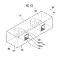
- FIG. 5A is a perspective view schematically showing a battery pack 400 according to a fourth embodiment of the present invention
- FIG. 5B is a perspective view showing a junction box 420 included within the battery pack 400 of FIG. 5A .
- the battery pack 400 according to the fourth embodiment is different from those according to the first, second and third embodiments in the number of junction boxes 420 .
- differences from the first, second and third embodiments will be mainly described, and overlapping descriptions will be omitted.
- the six surfaces of the housing 430 are defined by a housing bottom surface 436 adjacent to a bottom surface 426 of the junction box 420 , a housing top surface 435 opposite to the housing bottom surface 436 , a coolant inlet surface 431 having an inlet 437 formed thereon, a coolant outlet surface 433 formed opposite to the coolant inlet surface 431 , a first housing side surface 432 simultaneously positioned between the coolant inlet surface 431 and the coolant outlet surface 433 and between the housing bottom surface 436 is and the housing top surface 435 , and a second housing side surface 434 opposite to the first housing side surface 432 .
- the six surfaces of the junction box 420 are defined by the bottom surface 426 adjacent to the housing bottom surface 436 , a top surface 425 opposite to the bottom surface 426 , a first surface 421 adjacent to battery modules 410 , and second, third, fourth surfaces 422 , 423 and 424 disposed clockwise with respect to the first surface 421 .
- the third surface 423 is disposed adjacent to the coolant outlet surface 433 of the housing 430 , and two junction boxes 420 are spaced-apart from each other by a predetermined interval.
- sleeves 427 are provided in each of the two junction boxes 420 , respectively, the two sleeves 427 can serve as the coolant outlet for the battery pack 400 . Accordingly, a separate outlet is not necessary for the battery pack 400 according to the fourth embodiment of the present invention as shown in FIG. 5A . If desired, an outlet may be provided at a location on the coolant outlet surface 433 on which the junction boxes 420 are not disposed.
- An electronic component 429 is provided within each of the junction boxes 420 .
- Each electronic component 429 is disposed to come in contact with an outer wall 427 ow of a respective sleeve 427 .
- a heat dissipation member 428 such as a heat dissipation fin, is provided on an inner wall 427 iw of each sleeve 427 .
- the heat dissipation member 428 may actually be a plurality of heat dissipation members, and the plurality of heat dissipation members may be disposed at a predetermined interval on the inner wall 427 iw of each sleeve 427 .
- the electronic components 429 generate a large amount of heat, and can be a resistor, fuse or relay, which can be protection elements that prevent overcurrent and overload conditions from occurring.
- the heat generated as described above by the electronic components 429 may deteriorate battery cells 40 and cause a non-uniform heat distribution among the battery cells 40 .
- the heat dissipation members 428 are disposed on inner walls 427 iw of the sleeves 427 , which comes in contact with the electronic component 429 of the junction box 420 , so that the electronic components 429 can be easily cooled. Since the coolant flows through the sleeve 427 while coming in contact with the inner wall 427 iw of the sleeve 427 , the heat dissipation efficiency of the heat dissipation members 428 can be more improved. Particularly, when two junction boxes 420 are included, the two sleeves 427 each having the heat dissipation member 428 are included, so that the heat dissipation efficiency can be more improved as compared with the first two embodiments.
- the sleeves 427 are formed in each junction box 420 , so that it is possible to reduce a pressure drop generated due to the flow of the coolant being conventionally slowed down by the front of the junction box.
- the heat dissipation efficiency can be more improved, and the temperature variation s between the battery cells 40 can be decreased.
- a battery pack capable of improving heat dissipation characteristics and reducing the temperature variation between cells.
- a battery pack in which a heat-sink structure is disposed within a junction box so as to cool heat generated from an electronic component within the junction box, thereby preventing the deterioration of battery cells.
Landscapes
- Chemical & Material Sciences (AREA)
- Chemical Kinetics & Catalysis (AREA)
- Electrochemistry (AREA)
- General Chemical & Material Sciences (AREA)
- Engineering & Computer Science (AREA)
- Manufacturing & Machinery (AREA)
- Battery Mounting, Suspending (AREA)
- Secondary Cells (AREA)
Abstract
Description
Claims (20)
Applications Claiming Priority (2)
| Application Number | Priority Date | Filing Date | Title |
|---|---|---|---|
| KR1020110023351A KR101252936B1 (en) | 2011-03-16 | 2011-03-16 | Battery pack |
| KR10-2011-0023351 | 2011-03-16 |
Publications (2)
| Publication Number | Publication Date |
|---|---|
| US20120237804A1 US20120237804A1 (en) | 2012-09-20 |
| US8852773B2 true US8852773B2 (en) | 2014-10-07 |
Family
ID=46828714
Family Applications (1)
| Application Number | Title | Priority Date | Filing Date |
|---|---|---|---|
| US13/421,482 Active 2032-07-27 US8852773B2 (en) | 2011-03-16 | 2012-03-15 | Battery pack |
Country Status (2)
| Country | Link |
|---|---|
| US (1) | US8852773B2 (en) |
| KR (1) | KR101252936B1 (en) |
Cited By (6)
| Publication number | Priority date | Publication date | Assignee | Title |
|---|---|---|---|---|
| USD743285S1 (en) * | 2014-02-14 | 2015-11-17 | Checkpoint Systems, Inc. | Deactivator |
| USD751935S1 (en) * | 2014-02-14 | 2016-03-22 | Checkpoint Systems, Inc. | Deactivator |
| USD751936S1 (en) * | 2014-02-14 | 2016-03-22 | Checkpoint Systems, Inc. | Deactivator |
| US20170244141A1 (en) * | 2016-02-22 | 2017-08-24 | Faraday&Future Inc. | Temperature dependent fuse for battery cooling system |
| US10217693B1 (en) * | 2017-08-29 | 2019-02-26 | Nio Usa, Inc. | Methods and systems for high voltage component cooling in electric vehicle for fast charge |
| US10608301B2 (en) | 2017-08-29 | 2020-03-31 | Nio Usa, Inc. | Power electronics with integrated busbar cooling |
Families Citing this family (9)
| Publication number | Priority date | Publication date | Assignee | Title |
|---|---|---|---|---|
| CN102931449B (en) * | 2012-11-19 | 2014-12-03 | 上汽通用五菱汽车股份有限公司 | Heat radiation structure of automobile battery pack |
| DE102014215550A1 (en) * | 2014-08-06 | 2016-02-11 | Robert Bosch Gmbh | Electrical energy storage module and corresponding modular energy storage |
| KR102610042B1 (en) * | 2016-11-01 | 2023-12-06 | 현대모비스 주식회사 | integrated high voltage junction unit for electric vehicle |
| KR101926934B1 (en) * | 2016-12-12 | 2019-03-08 | 현대자동차주식회사 | Mounting structure of for high voltage junction block |
| US10034410B1 (en) * | 2017-04-26 | 2018-07-24 | Chroma Ate Inc. | Support apparatus |
| US10991924B2 (en) * | 2017-10-19 | 2021-04-27 | Tiveni Mergeco, Inc. | Pressure equalization between battery module compartments of an energy storage system and external environment |
| JP7505901B2 (en) * | 2020-03-18 | 2024-06-25 | 株式会社Subaru | Battery stack structure |
| DE102021209304A1 (en) | 2021-08-25 | 2023-03-02 | Robert Bosch Gesellschaft mit beschränkter Haftung | Cooling device for cooling a battery cell stack and battery system |
| CN118919986B (en) * | 2024-08-16 | 2025-05-09 | 南通杨天新能源有限公司 | Photovoltaic energy storage battery installation protection device |
Citations (9)
| Publication number | Priority date | Publication date | Assignee | Title |
|---|---|---|---|---|
| USD424525S (en) | 1998-07-16 | 2000-05-09 | Hubbell Incorported | Non-metallic housing for a pin and sleeve wiring device |
| KR20050018518A (en) | 2003-08-14 | 2005-02-23 | 현대자동차주식회사 | Cooling device for battery tray of electric vehicle |
| KR20060027579A (en) | 2004-09-23 | 2006-03-28 | 삼성에스디아이 주식회사 | Battery module temperature control system |
| US20070231678A1 (en) | 2005-10-14 | 2007-10-04 | Lg Chem, Ltd. | Heat exchanging system of battery pack using thermoelectric element |
| JP2008311016A (en) | 2007-06-13 | 2008-12-25 | Toyota Motor Corp | Battery pack |
| KR20090018417A (en) | 2007-08-17 | 2009-02-20 | 현대자동차주식회사 | Cooling system for fuel cell vehicle power cutoff device |
| JP2010097872A (en) | 2008-10-17 | 2010-04-30 | Denso Corp | Battery cooler |
| USD676814S1 (en) | 2012-06-05 | 2013-02-26 | Ivan W. Paul | Electrical junction box |
| USD688211S1 (en) | 2010-07-26 | 2013-08-20 | Hon Hai Precision Industry Co., Ltd. | Junction box |
-
2011
- 2011-03-16 KR KR1020110023351A patent/KR101252936B1/en not_active Expired - Fee Related
-
2012
- 2012-03-15 US US13/421,482 patent/US8852773B2/en active Active
Patent Citations (11)
| Publication number | Priority date | Publication date | Assignee | Title |
|---|---|---|---|---|
| USD424525S (en) | 1998-07-16 | 2000-05-09 | Hubbell Incorported | Non-metallic housing for a pin and sleeve wiring device |
| KR20050018518A (en) | 2003-08-14 | 2005-02-23 | 현대자동차주식회사 | Cooling device for battery tray of electric vehicle |
| KR20060027579A (en) | 2004-09-23 | 2006-03-28 | 삼성에스디아이 주식회사 | Battery module temperature control system |
| US20070231678A1 (en) | 2005-10-14 | 2007-10-04 | Lg Chem, Ltd. | Heat exchanging system of battery pack using thermoelectric element |
| KR100932214B1 (en) | 2005-10-14 | 2009-12-16 | 주식회사 엘지화학 | Heat exchange system of battery pack using thermoelectric elements |
| US7867663B2 (en) | 2005-10-14 | 2011-01-11 | Lg Chem, Ltd. | Heat exchanging system of battery pack using thermoelectric element |
| JP2008311016A (en) | 2007-06-13 | 2008-12-25 | Toyota Motor Corp | Battery pack |
| KR20090018417A (en) | 2007-08-17 | 2009-02-20 | 현대자동차주식회사 | Cooling system for fuel cell vehicle power cutoff device |
| JP2010097872A (en) | 2008-10-17 | 2010-04-30 | Denso Corp | Battery cooler |
| USD688211S1 (en) | 2010-07-26 | 2013-08-20 | Hon Hai Precision Industry Co., Ltd. | Junction box |
| USD676814S1 (en) | 2012-06-05 | 2013-02-26 | Ivan W. Paul | Electrical junction box |
Non-Patent Citations (4)
| Title |
|---|
| Definition of Junction Box from Webster dict online (http://www.merriam-webster.com/dictionary/junction%20box). |
| Definition of Junction Box from Wikipedia (http://en.wikipedia.org/wiki/Junction-box). |
| Korean Notice of Allowance issued on Mar. 25, 2013 in the corresponding Korean Patent Application No. 10-2011-0023351. |
| Korean Office Action issued on Sep. 17, 2012 by the KIPO for the corresponding Korean Patent Application No. 10-2011-0023351. |
Cited By (6)
| Publication number | Priority date | Publication date | Assignee | Title |
|---|---|---|---|---|
| USD743285S1 (en) * | 2014-02-14 | 2015-11-17 | Checkpoint Systems, Inc. | Deactivator |
| USD751935S1 (en) * | 2014-02-14 | 2016-03-22 | Checkpoint Systems, Inc. | Deactivator |
| USD751936S1 (en) * | 2014-02-14 | 2016-03-22 | Checkpoint Systems, Inc. | Deactivator |
| US20170244141A1 (en) * | 2016-02-22 | 2017-08-24 | Faraday&Future Inc. | Temperature dependent fuse for battery cooling system |
| US10217693B1 (en) * | 2017-08-29 | 2019-02-26 | Nio Usa, Inc. | Methods and systems for high voltage component cooling in electric vehicle for fast charge |
| US10608301B2 (en) | 2017-08-29 | 2020-03-31 | Nio Usa, Inc. | Power electronics with integrated busbar cooling |
Also Published As
| Publication number | Publication date |
|---|---|
| US20120237804A1 (en) | 2012-09-20 |
| KR20120105731A (en) | 2012-09-26 |
| KR101252936B1 (en) | 2013-04-09 |
Similar Documents
| Publication | Publication Date | Title |
|---|---|---|
| US8852773B2 (en) | Battery pack | |
| KR102029407B1 (en) | Battery system | |
| JP7037005B2 (en) | Battery pack with louver fin shaped heat transfer medium | |
| US11444353B2 (en) | Battery pack | |
| KR102259217B1 (en) | Battery System and Vehicle Comprising the Same | |
| KR101261736B1 (en) | Battery Pack | |
| CN109328405B (en) | Battery module carrier, battery module and vehicle with battery system | |
| US10011162B2 (en) | Power switching module for battery module assembly | |
| EP3316340B1 (en) | Battery module | |
| CN107946503B (en) | Battery module carrier and battery system | |
| US8835036B2 (en) | Battery pack | |
| JP2019525397A (en) | Battery submodule carrier, battery submodule, battery system and automobile | |
| KR20150102632A (en) | Rechargeable battery pack | |
| KR20190080717A (en) | Battery module | |
| CN111081926B (en) | Battery module | |
| KR20130005756A (en) | Battery having heat-conductive case for water cooling | |
| US12015163B2 (en) | Eco-friendly power source such as battery module for a transportation vehicle and method of manufacturing battery module | |
| WO2013080338A1 (en) | Cell block and cell module having same | |
| KR102061292B1 (en) | Battery module, battery pack comprising the battery module and vehicle comprising the battery pack | |
| KR20160068446A (en) | Battery module, and battery pack including the same | |
| KR20240114910A (en) | Battery pack | |
| KR102931022B1 (en) | Battery pack and device including the same | |
| US20250385370A1 (en) | Battery module and battery pack including the same | |
| EP4507087A1 (en) | Battery pack and device comprising same | |
| KR20240100264A (en) | Battery module and battery pack including the same |
Legal Events
| Date | Code | Title | Description |
|---|---|---|---|
| AS | Assignment |
Owner name: SB LIMOTIVE CO., LTD., A CORPORATION CHARTERED IN Free format text: ASSIGNMENT OF ASSIGNORS INTEREST;ASSIGNOR:YOON, JI-HYOUNG;REEL/FRAME:028169/0134 Effective date: 20120314 |
|
| AS | Assignment |
Owner name: ROBERT BOSCH GMBH, GERMANY Free format text: ASSIGNMENT OF ASSIGNORS INTEREST;ASSIGNOR:SB LIMOTIVE CO., LTD.;REEL/FRAME:029819/0407 Effective date: 20121114 Owner name: SAMSUNG SDI CO., LTD., KOREA, REPUBLIC OF Free format text: ASSIGNMENT OF ASSIGNORS INTEREST;ASSIGNOR:SB LIMOTIVE CO., LTD.;REEL/FRAME:029819/0407 Effective date: 20121114 |
|
| FEPP | Fee payment procedure |
Free format text: PAYOR NUMBER ASSIGNED (ORIGINAL EVENT CODE: ASPN); ENTITY STATUS OF PATENT OWNER: LARGE ENTITY |
|
| STCF | Information on status: patent grant |
Free format text: PATENTED CASE |
|
| MAFP | Maintenance fee payment |
Free format text: PAYMENT OF MAINTENANCE FEE, 4TH YEAR, LARGE ENTITY (ORIGINAL EVENT CODE: M1551) Year of fee payment: 4 |
|
| MAFP | Maintenance fee payment |
Free format text: PAYMENT OF MAINTENANCE FEE, 8TH YEAR, LARGE ENTITY (ORIGINAL EVENT CODE: M1552); ENTITY STATUS OF PATENT OWNER: LARGE ENTITY Year of fee payment: 8 |
|
| MAFP | Maintenance fee payment |
Free format text: PAYMENT OF MAINTENANCE FEE, 12TH YEAR, LARGE ENTITY (ORIGINAL EVENT CODE: M1553); ENTITY STATUS OF PATENT OWNER: LARGE ENTITY Year of fee payment: 12 |