US8852522B1 - Plasma de-activation apparatus and method - Google Patents
Plasma de-activation apparatus and method Download PDFInfo
- Publication number
- US8852522B1 US8852522B1 US13/684,726 US201213684726A US8852522B1 US 8852522 B1 US8852522 B1 US 8852522B1 US 201213684726 A US201213684726 A US 201213684726A US 8852522 B1 US8852522 B1 US 8852522B1
- Authority
- US
- United States
- Prior art keywords
- plasma
- chamber
- tuned
- passageway
- gases
- Prior art date
- Legal status (The legal status is an assumption and is not a legal conclusion. Google has not performed a legal analysis and makes no representation as to the accuracy of the status listed.)
- Active, expires
Links
Images


Classifications
-
- B—PERFORMING OPERATIONS; TRANSPORTING
- B01—PHYSICAL OR CHEMICAL PROCESSES OR APPARATUS IN GENERAL
- B01J—CHEMICAL OR PHYSICAL PROCESSES, e.g. CATALYSIS OR COLLOID CHEMISTRY; THEIR RELEVANT APPARATUS
- B01J19/00—Chemical, physical or physico-chemical processes in general; Their relevant apparatus
- B01J19/08—Processes employing the direct application of electric or wave energy, or particle radiation; Apparatus therefor
- B01J19/087—Processes employing the direct application of electric or wave energy, or particle radiation; Apparatus therefor employing electric or magnetic energy
- B01J19/088—Processes employing the direct application of electric or wave energy, or particle radiation; Apparatus therefor employing electric or magnetic energy giving rise to electric discharges
-
- H—ELECTRICITY
- H01—ELECTRIC ELEMENTS
- H01J—ELECTRIC DISCHARGE TUBES OR DISCHARGE LAMPS
- H01J37/00—Discharge tubes with provision for introducing objects or material to be exposed to the discharge, e.g. for the purpose of examination or processing thereof
- H01J37/32—Gas-filled discharge tubes
-
- H—ELECTRICITY
- H05—ELECTRIC TECHNIQUES NOT OTHERWISE PROVIDED FOR
- H05H—PLASMA TECHNIQUE; PRODUCTION OF ACCELERATED ELECTRICALLY-CHARGED PARTICLES OR OF NEUTRONS; PRODUCTION OR ACCELERATION OF NEUTRAL MOLECULAR OR ATOMIC BEAMS
- H05H1/00—Generating plasma; Handling plasma
- H05H1/24—Generating plasma
- H05H1/2406—Generating plasma using dielectric barrier discharges, i.e. with a dielectric interposed between the electrodes
- H05H1/2443—Generating plasma using dielectric barrier discharges, i.e. with a dielectric interposed between the electrodes the plasma fluid flowing through a dielectric tube
- H05H1/2465—Generating plasma using dielectric barrier discharges, i.e. with a dielectric interposed between the electrodes the plasma fluid flowing through a dielectric tube the plasma being activated by inductive coupling, e.g. using coiled electrodes
-
- B—PERFORMING OPERATIONS; TRANSPORTING
- B01—PHYSICAL OR CHEMICAL PROCESSES OR APPARATUS IN GENERAL
- B01J—CHEMICAL OR PHYSICAL PROCESSES, e.g. CATALYSIS OR COLLOID CHEMISTRY; THEIR RELEVANT APPARATUS
- B01J2219/00—Chemical, physical or physico-chemical processes in general; Their relevant apparatus
- B01J2219/08—Processes employing the direct application of electric or wave energy, or particle radiation; Apparatus therefor
- B01J2219/0873—Materials to be treated
- B01J2219/0879—Solid
-
- H—ELECTRICITY
- H05—ELECTRIC TECHNIQUES NOT OTHERWISE PROVIDED FOR
- H05H—PLASMA TECHNIQUE; PRODUCTION OF ACCELERATED ELECTRICALLY-CHARGED PARTICLES OR OF NEUTRONS; PRODUCTION OR ACCELERATION OF NEUTRAL MOLECULAR OR ATOMIC BEAMS
- H05H1/00—Generating plasma; Handling plasma
- H05H1/24—Generating plasma
- H05H1/2406—Generating plasma using dielectric barrier discharges, i.e. with a dielectric interposed between the electrodes
- H05H1/2443—Generating plasma using dielectric barrier discharges, i.e. with a dielectric interposed between the electrodes the plasma fluid flowing through a dielectric tube
Definitions
- This invention relates to the use of a plasma or a glow discharge for dissociating one or more gases into reactive and non-reactive ionic and reactive and non-reactive neutral species, and in particular, to de-activating such a plasma.
- Plasma apparatus can be divided into two broad categories, downstream or remote plasma and direct plasma.
- downstream plasma the article(s) are not immersed in the glow discharge, as it is in direct plasma.
- the result is a purely chemical and multi-directional process resulting in a somewhat more gentle treatment of the article(s) because high power electromagnetic waves at high frequency are not coupled through the article(s) and there is no heating from direct ion bombardment.
- one or more reactive gases such as, oxygen-based gases, or halogen-based gases, including fluorine, chlorine, bromine, or other equivalent gases, as well as gas molecular compounds having one or more oxygen or halogen atoms
- reactive gases such as, oxygen-based gases, or halogen-based gases, including fluorine, chlorine, bromine, or other equivalent gases, as well as gas molecular compounds having one or more oxygen or halogen atoms
- a major problem to solve in order to obtain an electrically charge free process is the need for de-activation of a plasma, such as the need for recombination of the charged particles to form neutral particles.
- De-activation of the plasma means the removal of all electrically charged reactive and un-reactive species from the plasma.
- the de-activation of a plasma is achieved by using a long path (up to one meter in length) from the plasma chamber to a sample chamber, or the use of baffles to essentially increase the path length by convolutions so that a plasma is de-activated before it reaches the sample chamber.
- Another option is to use a wire mesh screen between the plasma generation chamber and the sample chamber to form a Faraday shield.
- the present invention includes a passageway in the exhaust side of the discharge chamber or plasma chamber containing one or more gases, where a de-activation of the plasma can be achieved before the plasma travels further towards a sample.
- one or more gases are dissociated, which could include one or more inert gases and one or more reactive gases (e.g., a oxygen-based or halogen-based gas) with or without other gases.
- the invention can be implemented in numerous ways, such as by a method, an apparatus, or a plasma system. Four aspects of the invention are described below.
- a first aspect of the invention is directed to a method for treating one or more articles with a selectively de-activated plasma generated from dissociating one or more gases.
- the method includes supplying one or more gases from a source to a first chamber; applying RF power to dissociate said one or more gases and create a plasma; withdrawing the dissociated one or more gases from the first chamber through a passageway, wherein the passageway has a tuned LC circuit with a tuned frequency to selectively de-activate plasma in the passageway; and supplying the dissociated one or more gases to a second chamber containing one or more articles.
- a second aspect of the invention is directed to a method for treating one or more articles with a selectively de-activated plasma generated by dissociating one or more gases.
- the method includes supplying one or more gases from a first source to a first chamber, applying RF power to dissociate one or more gases in the first source and create a first plasma, withdrawing the first plasma from said first chamber through a first passageway and selectively de-activating the first plasma with a first passageway having a first tuned LC circuit having a first tuned frequency to selectively de-activate the first plasma; supplying one or more gases from a second source to a second chamber for RF power to dissociate said one or more gases from the second source to create a second plasma; using a second passageway to withdraw the second plasma from the second chamber and selectively de-activating the second plasma in said second passageway having a second tuned LC circuit having a second tuned frequency to selectively de-activate the second plasma; and supplying de-activated first plasma from the first chamber and de-activated second plasma
- a third aspect of the invention is directed to an apparatus to dissociate one or more gases to produce a plasma.
- the apparatus includes a first chamber with a first passageway, coupled to a first source of one or more gases; one or more RF energy sources coupled to the first chamber; means for disassociating the one or more gases in the first chamber into a plasma; a second passageway having a tuned LC circuit to selectively de-activate the plasma into a de-activated plasma, and a second chamber coupled to the first chamber through the second passageway to receive the de-activated plasma, wherein the second chamber contains one or more articles.
- a fourth aspect of the invention is directed to an apparatus to dissociate one or more gases to produce a plasma.
- the apparatus includes a first chamber with a first passageway, coupled to a first source of one or more gases; a second chamber with a second passageway, coupled to a second source of one or more gases; one or more RF energy sources coupled to the first chamber and the second chamber; means for dissociating the one or more gases from the first port into a first plasma in the first chamber and for dissociating one or more gases from the second port into a second plasma in the second chamber; at least one passageway having an externally modifiable tuned LC circuit to selectively de-activate at least one plasma from either the first chamber or from the second chamber; and a third chamber coupled to the first chamber and the second chamber, wherein the third chamber contains one or more articles.
- FIG. 1 illustrates a plasma generating and de-activation apparatus constructed in accordance with one embodiment of the invention.
- FIG. 2 illustrates a plasma generating and de-activation apparatus constructed in accordance with an alternative embodiment the invention.
- FIG. 3 illustrates a plasma generating and de-activation apparatus constructed in accordance with an alternative embodiment of the invention.
- FIG. 4 illustrates a plasma generating and de-activation apparatus constructed in accordance with an alternative embodiment of the invention.
- FIG. 5 illustrates a plasma generating and de-activation apparatus constructed in accordance with an alternative embodiment of the invention.
- FIG. 6A illustrates a plasma generating and de-activation apparatus constructed in accordance with one embodiment of the invention.
- FIG. 6B illustrates a plasma generating and de-activation apparatus constructed in accordance with one embodiment of the invention, with an adjustable external inductor.
- FIG. 7B illustrates an alternative embodiment of the invention in which two discharge chambers operate in series.
- FIG. 8 illustrates a schematic cross-section of a chamber for processing one or more articles, in accordance with another embodiment of the invention.
- FIG. 9 illustrates a flowchart of a method to generate and de-activate a plasma, according to an alternative embodiment of the invention.
- FIG. 11 illustrates a flowchart of a method to generate and de-activate a plasma in parallel, according to an alternative embodiment of the invention.
- FIG. 12 illustrates a flowchart of a method to generate and de-activate a plasma in series, according to an alternative embodiment of the invention.
- the invention provides a method, an apparatus, and a system to de-activate a plasma.
- Various embodiments of the invention can be applied to biological applications, medical applications, chemical applications, electronic applications, and any other applications where plasma can be beneficially used.
- Inductive coupling or capacitive coupling can be used to couple radio-frequency (RF) electromagnetic energy to one or more gases for dissociation and creation of plasma.
- RF radio-frequency
- radio-frequency (RF) is defined as any frequency of electromagnetic energy where inductive coupling to a plasma and a tuned LC circuit can be implemented.
- a selectively tuned LC circuit can be tuned to the same frequency (and/or a harmonic of the same frequency) that was used to generate a plasma, so that the selectively tuned LC circuit can de-activate and remove energy from a plasma. Certain embodiments of the invention can de-activate plasma and also at the same time be used to maximize the production of activated neutral atoms and molecules from a plasma source.
- a plasma generating discharge chamber includes a gas inlet 120 which supplies one or more gases to discharge chamber 111 .
- Discharge chamber 111 also has a capillary tube 110 to prevent plasma expansion into gas inlet 120 .
- One or more radio-frequency (RF) energy sources 170 are coupled to inductor 115 , which surrounds discharge chamber 111 and dissociates one or more gases passing through discharge chamber 111 , which may be made of various materials (e.g., a dielectric material or an equivalent).
- Discharge chamber 111 is coupled to a sample chamber (not shown) by a passageway 118 and an output port 114 .
- Passageway 118 has a tuned LC circuit 105 that is grounded on the exhaust side of the passageway 118 to prevent unwanted capacitive coupling if a Faraday shield is not used, and that can be selectively tuned by a user (e.g., by adjusting an external variable capacitor and/or inductor) to match the same radio frequency used to generate the plasma in the discharge chamber 111 , and thereby de-activate and remove energy and charged particles from the plasma.
- a user e.g., by adjusting an external variable capacitor and/or inductor
- the passageway 118 can be fabricated from quartz or ceramic tubes, or tubes of equivalent materials.
- the tuned LC circuit 105 includes electrically conductive metal (e.g., copper, silver, aluminum, gold, or various metal alloys or electrically conductive coatings, or equivalents), such as wires with a gauge of 12 to 18, or coils including electrically conductive metal with a diameter ranging from one eighth of an inch ( ⁇ 0.3 centimeters) to one quarter of an inch ( ⁇ 0.6 centimeters).
- the tuned LC circuit 105 is wound around a Faraday shield (not shown) to prevent undesirable capacitive coupling and increase the inductive coupling between the plasma and the tuned LC circuit.
- 12 to 18 gauge conductive metal wire is wound around a magnetic core as shown on FIG. 6A when RF power levels are low (for example, less than 500 watts). In one embodiment, the conductive metal wire is wound around the passageway 118 and cooled by forced air.
- the choice of cooling for the coil and the type of capacitor used in the tuned LC circuit are a function of the RF electrical current to be handled by the tuned LC circuit.
- a variable air capacitor is used when the current flow in the tuned LC circuit is low.
- the preferred range of values for C are 50 pF (picoFarads) to 25 pF (picoFarads) and the corresponding values for total inductance (L of the coil+L1 of an external inductor) will be 2.7 uH (microHenrys) to 5.5 uH (microHenrys).
- a plasma generating chamber has a gas inlet 120 which supplies one or more gases to discharge chamber 111 .
- a metal or dielectric material 184 encloses gas inlet 120 and a dielectric layer 182 has small openings (e.g., holes, slots, or equivalent perforations) 180 to prevent plasma expansion upstream from discharge chamber 111 through gas inlet 120 .
- One or more RF energy sources 170 are coupled to inductor 115 , which surrounds discharge chamber 111 and dissociates one or more gases passing through discharge chamber 111 .
- the discharge chamber walls 200 may be made of various materials (e.g., a dielectric material such as, ceramic, glass, or an equivalent).
- Discharge chamber 111 is coupled to a sample chamber (not shown) by a passageway 118 and an output port 114 .
- the passageway 118 can be fabricated from quartz or ceramic tubes.
- Passageway 118 has a tuned LC circuit 105 that is grounded on the exhaust side of the passageway 118 to prevent unwanted capacitive coupling if a Faraday shield is not used, and that can be selectively tuned by a user (e.g., by adjusting an external variable capacitor and/or inductor) to match the same radio frequency used to generate the plasma in the discharge chamber 111 , and thereby de-activate and remove energy and charged particles from the plasma.
- gas inlet 120 with a means to control backwards plasma expansion supplies one or more gases to discharge chamber 111 .
- Discharge chamber 111 also has a dielectric layer 182 between the discharge chamber 111 and a protruding first electrode 190 . Both the first electrode 190 and a second electrode 192 are connected to one or more RF energy sources 170 . One or more RF energy sources 170 provide the power to dissociate one or more gases passing through discharge chamber 111 .
- Discharge chamber 111 is coupled to a sample chamber (not shown) by a passageway 118 and an output port 114 .
- the passageway 118 can be fabricated from quartz or ceramic tubes.
- Passageway 118 has a tuned LC circuit 105 that is grounded on the exhaust side of the passageway 118 to prevent unwanted capacitive coupling if a Faraday shield is not used, and that can be selectively tuned by a user (e.g., by adjusting an external variable capacitor and/or inductor) to match the same radio frequency used to generate the plasma in the discharge chamber 111 , and thereby de-activate and remove energy and charged particles from the plasma.
- a user e.g., by adjusting an external variable capacitor and/or inductor
- the tuned LC circuit 105 includes electrically conductive metal (e.g., copper, silver, aluminum, gold, or various metal alloys or electrically conductive coatings, or equivalents), such as wires with a gauge of 12 to 18, or coils including electrically conductive metal with a diameter ranging from one eighth of an inch ( ⁇ 0.3 centimeters) to one quarter of an inch ( ⁇ 0.6 centimeters).
- the tuned LC circuit 105 is wound around a Faraday shield (not shown) to increase the inductive coupling between the plasma and the tuned LC circuit.
- 12 to 18 gauge conductive metal wire is wound around a magnetic core as shown on FIG. 6A when RF power levels are low (for example, less than 500 watts).
- the conductive metal wire is wound around the passageway 118 and cooled by forced air.
- a plasma generating discharge chamber includes a gas inlet 120 which supplies one or more gases to discharge chamber 111 .
- Discharge chamber 111 also has a capillary tube 110 to prevent plasma expansion into gas inlet 120 .
- One or more radio-frequency (RF) energy sources 170 are coupled to inductor 115 , which surrounds discharge chamber 111 and dissociates one or more gases passing through discharge chamber 111 , which may be made of various materials (e.g., a dielectric material or an equivalent).
- Discharge chamber 111 is coupled to a sample chamber (not shown) by a passageway 118 .
- the tuned LC circuit 105 includes electrically conductive metal (e.g., copper, silver, aluminum, gold, or various metal alloys or electrically conductive coatings, or equivalents), such as wires with a gauge of 12 to 18, or coils including electrically conductive metal with a diameter ranging from one eighth of an inch ( ⁇ 0.3 centimeters) to one quarter of an inch ( ⁇ 0.6 centimeters).
- 12 to 18 gauge conductive metal wire is wound around a magnetic core as shown on FIG. 6A when RF power levels are low (for example, less than 500 watts).
- the conductive metal wire is wound around the passageway 118 and cooled by forced air.
- the tuned LC circuit 105 and tuned LC circuit 109 are wrapped around a Faraday shield 108 to increase the inductive coupling between the plasma and the tuned LC circuit 105 .
- the passageway 118 can be fabricated from quartz or ceramic tubes.
- the tuned LC circuit 105 is grounded and can be selectively tuned by a user (e.g., by adjusting an external variable capacitor and/or inductor) to match the same radio frequency used to generate the plasma in the discharge chamber 111 , and thereby de-activate and remove energy and charged particles from the plasma.
- the tuned LC circuit 105 and tuned LC circuit 109 include electrically conductive metal (e.g., copper, silver, aluminum, gold, or various metal alloys or electrically conductive coatings, or equivalents), such as wires with a gauge of 12 to 18, or coils including electrically conductive metal with a diameter ranging from one eighth of an inch ( ⁇ 0.3 centimeters) to one quarter of an inch ( ⁇ 0.6 centimeters).
- 12 to 18 gauge conductive metal wire is wound around a magnetic core as shown on FIG. 6A when RF power levels are low (for example, less than 500 watts).
- the conductive metal wire is wound around the passageway 118 and cooled by forced air.
- a plasma generating discharge chamber includes a gas inlet 120 which supplies one or more gases to discharge chamber 111 .
- Discharge chamber 111 also has a capillary tube 110 to prevent plasma expansion into gas inlet 120 .
- One or more radio-frequency (RF) energy sources 170 are coupled to inductor 115 , which surrounds discharge chamber 111 and dissociates one or more gases passing through discharge chamber 111 , which may be made of various materials (e.g., a dielectric material or an equivalent).
- Discharge chamber 111 is coupled to a sample chamber (not shown) by a passageway 118 and an output port 114 .
- the passageway 118 can be fabricated from quartz or ceramic tubes.
- Passageway 118 has a tuned LC circuit 105 that is grounded on the exhaust side of the passageway 118 to prevent unwanted capacitive coupling if a Faraday shield is not used, and the tuned LC circuit 105 includes a toroidal coil 106 that is grounded, where the tuned LC circuit 105 can be selectively tuned by a user (e.g., by adjusting an external variable capacitor and/or inductor) to match the same radio frequency (or a harmonic of the frequency) used to generate the plasma in the discharge chamber 111 , and thereby de-activate and remove energy and charged particles from the plasma.
- a user e.g., by adjusting an external variable capacitor and/or inductor
- the tuned LC circuit 105 includes electrically conductive metal (e.g., copper, silver, aluminum, gold, or various metal alloys or electrically conductive coatings, or equivalents), such as wires with a gauge of 12 to 18, or coils including electrically conductive metal with a diameter ranging from one eighth of an inch ( ⁇ 0.3 centimeters) to one quarter of an inch ( ⁇ 0.6 centimeters).
- electrically conductive metal e.g., copper, silver, aluminum, gold, or various metal alloys or electrically conductive coatings, or equivalents
- the tuned LC circuit 105 is wrapped around a Faraday shield (not shown) to increase the inductive coupling between the plasma and the tuned LC circuit.
- forced air cooling of the passageway 118 is used.
- incompatible chamber materials and gas types such as quartz and fluorine gas
- multiple plasma sources can be used to dissociated each gas independently and the exhaust gas is combined to provide the desired mix of chemicals, such as in FIG. 7A .
- a plasma generating discharge chamber includes a gas inlet 120 which supplies one or more gases to discharge chamber 111 .
- Discharge chamber 111 also has a capillary tube 110 to prevent plasma expansion into gas inlet 120 .
- One or more radio-frequency (RF) energy sources 170 are coupled to inductor 115 , which surrounds discharge chamber 111 and dissociates one or more gases passing through discharge chamber 111 , which may be made of various materials (e.g., a dielectric material or an equivalent).
- Discharge chamber 111 is coupled to a sample chamber (not shown) by a passageway 118 .
- the passageway 118 can be fabricated from quartz or ceramic tubes.
- Passageway 118 has a tuned LC circuit 105 that is grounded on the exhaust side of the passageway 118 to prevent unwanted capacitive coupling if a Faraday shield is not used, and includes an external inductor L1, where the tuned LC circuit 105 can be selectively tuned by a user (e.g., by adjusting an external variable capacitor and/or the inductor L1) to match the same radio frequency used to generate the plasma in the discharge chamber 111 , and thereby de-activate and remove energy and charged particles from the plasma.
- a user e.g., by adjusting an external variable capacitor and/or the inductor L1
- the tuned LC circuit 105 includes electrically conductive metal (e.g., copper, silver, aluminum, gold, or various metal alloys or electrically conductive coatings, or equivalents), such as wires with a gauge of 12 to 18, or coils including electrically conductive metal with a diameter ranging from one eighth of an inch ( ⁇ 0.3 centimeters) to one quarter of an inch ( ⁇ 0.6 centimeters), or coiled conductive metal tubes with an equal or larger diameter.
- electrically conductive metal e.g., copper, silver, aluminum, gold, or various metal alloys or electrically conductive coatings, or equivalents
- Discharge chamber 111 is coupled to chamber 313 by passageway 118 and discharge chamber 311 is coupled to chamber 313 by passageway 119 .
- Passageway 118 has a tuned LC circuit 105 that is grounded on the exhaust side of the passageway 118 to prevent unwanted capacitive coupling if a Faraday shield is not used, that can be selectively tuned by a user (e.g., by adjusting an external variable capacitor and/or inductor) to match the same radio frequency used to generate the plasma in the discharge chamber 111 , and thereby de-activate and remove energy and charged particles from the plasma.
- the passageways 118 and 119 can be independently fabricated from quartz or ceramic tubes, or tubes of equivalent materials.
- the tuned LC circuit 105 and/or 107 includes copper wires of gauge 12 to 18 , or coiled tubes with a diameter ranging from one eighth of an inch ( ⁇ 0.3 centimeters) to one quarter of an inch ( ⁇ 0.6 centimeters).
- the materials used to construct the passageways 118 and 119 can all be independently selected as desired.
- the materials used to construct the passageways 118 and 119 can be selected to be reactive or non-reactive with the plasma to which they are exposed.
- FIG. 8 is a schematic cross-section of a chamber 861 for processing one or more articles.
- Chamber 861 includes one or more supply ports, such as supply port 863 , for receiving one or more dissociated gases and distributing them uniformly over article(s) 865 on platen 866 .
- platen 866 and/or chamber 861 are temperature-controlled to control the temperature of the article(s) 865 .
- Gases are removed from chamber 861 by a suitable vacuum pump (not shown) through one or more exhaust ports 868 .
- chamber 861 itself contains a plasma (not shown) generated directly in chamber 861 , in addition to plasma supplied from other chambers.
- FIG. 9 illustrates a flowchart of a method to provide plasma, according to one embodiment of the invention.
- the sequence starts in operation 902 .
- Operation 904 includes supplying one or more gases from a source to a first chamber. This operation in some embodiments of the invention would include using a means for controlling (i.e., reducing or preventing) expansion of plasma back through the source from the first chamber.
- Operation 906 includes applying RF power to dissociate one or more gases and create a plasma.
- Operation 908 includes withdrawing the one or more dissociated gases from the first chamber through a passageway coupled to a tuned LC circuit selectively tuned to de-activate the plasma.
- Operation 910 includes supplying the one or more dissociated gases to a second chamber containing one or more articles. The method ends in operation 912 .
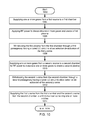
- FIG. 10 illustrates a flowchart of a method to provide plasma, according to an alternative embodiment of the invention.
- the sequence starts in operation 1002 .
- Operation 1004 is next and includes supplying one or more gases from a first source to a first chamber.
- Operation 1006 includes applying RF power to dissociate one or more gases and create a first plasma.
- Operation 1008 includes withdrawing the first plasma from the first chamber through a first passageway having first tuned LC circuit to allow selective de-activation of the first plasma.
- Operation 1010 includes supplying one or more gases from a second source to a second chamber for RF power to dissociate one or more gases to create a second plasma.
- Operation 1012 includes withdrawing the second plasma from the second chamber through a second passageway having a second tuned LC circuit to allow selective de-activation of the second plasma.
- Operation 1014 includes supplying the first plasma from the first chamber and the second plasma from the second chamber to a third chamber containing one or more articles. The method ends in operation 1016 .
- one or more tuned LC circuits include externally modifiable inductors to allow a user to adjust the frequency of the tuned LC circuit to have no de-activation effects or reduced de-activation effects on the plasma, or to have a full de-activation effect on the plasma.
- one or more tuned LC circuits include a Faraday shield to increase the inductive coupling to the plasma during de-activation.
- the first chamber and the second chamber are constructed differently and use either inductive coupling or capacitive coupling to apply RF power to the chambers.
- the first chamber and the second chamber are constructed identically.
- FIG. 11 illustrates a flowchart of a method to provide de-activated plasma, according to an alternative embodiment of the invention.
- the sequence starts in operation 1102 .
- Operation 1104 includes supplying one or more gases to a first chamber.
- Operation 1106 includes applying RF power to dissociate one or more gases to create a first plasma.
- Operation 1108 includes withdrawing the first plasma from the first chamber through a first passageway inductively coupled to a tuned LC circuit to allow selective de-activation of the first plasma.
- Operation 1110 includes supplying one or more gases to a second chamber for RF power to dissociate one or more gases (identical or different to the one or more gases in the first chamber) to create a second plasma.
- Operation 1112 includes withdrawing the second plasma from the second chamber through a second passageway inductively coupled to a tuned LC circuit to allow selective de-activation of the second plasma.
- Operation 1114 includes positioning the exhaust of the first and second plasmas (first and second passageways) in front of each other so that the plasma is enhanced in selected locations.
- Operation 1116 includes supplying the first plasma and second plasma to a third chamber containing one or more articles. The method ends in operation 1118 .
- one or more tuned LC circuits include an externally modifiable capacitor and/or inductor to allow a user to adjust the frequency of the tuned LC circuit to have no de-activation effects or reduced de-activation effects on the plasma, or to have a full de-activation effect on the plasma.
- one or more tuned LC circuits include a Faraday shield to increase the inductive coupling to the plasma during de-activation.
- the first chamber and the second chamber are constructed differently and use either inductive coupling or capacitive coupling to apply RF power to the chambers.
- the first chamber and second chamber are constructed identically.
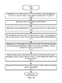
- FIG. 12 illustrates a flowchart of a method to provide a de-activated plasma in series, according to an alternative embodiment of the invention.
- the sequence starts in operation 1202 .
- Operation 1204 includes positioning one or more tuned LC circuits around one or more passageways from one or more chambers to allow a selective de-activation of a plasma.
- Operation 1206 includes supplying one or more gases to a first chamber.
- Operation 1206 in one embodiment of the invention would include a means for controlling the upstream expansion of the one or more gases.
- Operation 1208 includes applying RF power to dissociate one or more gases and create a first plasma.
- Operation 1210 includes withdrawing the first plasma from the first chamber through a first passageway having a first tuned LC circuit to allow selective de-activation of the first plasma.
- Operation 1212 includes supplying one or more gases to a second chamber in series to the first chamber to dissociate one or more gases (identical or different to the one or more gases in the first chamber) to create a second plasma.
- Operation 1214 includes withdrawing the second plasma from the second chamber through a second passageway having a second tuned LC circuit to allow selective de-activation of the second plasma.
- Operation 1216 includes supplying the first plasma and second plasma to a third chamber containing one or more articles. The method ends in operation 1218 .
- one or more tuned LC circuits include an externally modifiable capacitor or inductor to allow a user to adjust the frequency of the tuned LC circuit to have no de-activation effects or reduced de-activation effects on the plasma, or to have a full de-activation effect on the plasma.
- one or more tuned LC circuits include a Faraday shield to increase the inductive coupling to the plasma during de-activation.
- the first chamber and the second chamber are constructed differently and use either inductive coupling or capacitive coupling to apply RF power to the chambers.
Abstract
Description
L*C*(2*3.1416*F)exp2=1 (1)
The preferred range of values for C are 50 pF (picoFarads) to 25 pF (picoFarads) and the corresponding values for total inductance (L of the coil+L1 of an external inductor) will be 2.7 uH (microHenrys) to 5.5 uH (microHenrys).
Claims (21)
Priority Applications (1)
| Application Number | Priority Date | Filing Date | Title |
|---|---|---|---|
| US13/684,726 US8852522B1 (en) | 2012-11-26 | 2012-11-26 | Plasma de-activation apparatus and method |
Applications Claiming Priority (1)
| Application Number | Priority Date | Filing Date | Title |
|---|---|---|---|
| US13/684,726 US8852522B1 (en) | 2012-11-26 | 2012-11-26 | Plasma de-activation apparatus and method |
Publications (1)
| Publication Number | Publication Date |
|---|---|
| US8852522B1 true US8852522B1 (en) | 2014-10-07 |
Family
ID=51626905
Family Applications (1)
| Application Number | Title | Priority Date | Filing Date |
|---|---|---|---|
| US13/684,726 Active 2033-06-01 US8852522B1 (en) | 2012-11-26 | 2012-11-26 | Plasma de-activation apparatus and method |
Country Status (1)
| Country | Link |
|---|---|
| US (1) | US8852522B1 (en) |
Citations (1)
| Publication number | Priority date | Publication date | Assignee | Title |
|---|---|---|---|---|
| US20050178746A1 (en) * | 2004-02-18 | 2005-08-18 | Gorin Georges J. | Higher power density downstream plasma |
-
2012
- 2012-11-26 US US13/684,726 patent/US8852522B1/en active Active
Patent Citations (1)
| Publication number | Priority date | Publication date | Assignee | Title |
|---|---|---|---|---|
| US20050178746A1 (en) * | 2004-02-18 | 2005-08-18 | Gorin Georges J. | Higher power density downstream plasma |
Similar Documents
| Publication | Publication Date | Title |
|---|---|---|
| US7015415B2 (en) | Higher power density downstream plasma | |
| US5430355A (en) | RF induction plasma source for plasma processing | |
| US7863582B2 (en) | Ion-beam source | |
| US7648611B2 (en) | Plasma etching equipment | |
| US9697993B2 (en) | Non-ambipolar plasma ehncanced DC/VHF phasor | |
| JPS63184233A (en) | Inductive excitation type iron source | |
| US20160042916A1 (en) | Post-chamber abatement using upstream plasma sources | |
| US20150000844A1 (en) | Multiple-mode plasma generation apparatus | |
| CN103766001B (en) | Plasma generating device and CVD device | |
| US9263237B2 (en) | Plasma processing apparatus and method thereof | |
| KR20100031960A (en) | Plasma generating apparatus | |
| JP2006221852A (en) | Induction coupled plasma generator | |
| CN101805895A (en) | Helicon wave plasma enhanced chemical vapor deposition unit | |
| CN110993479B (en) | Remote plasma source generating device and semiconductor processing equipment | |
| WO2002097937A1 (en) | Inductively coupled high-density plasma source | |
| CN108668422A (en) | A kind of plasma generates chamber and plasma processing apparatus | |
| KR100751535B1 (en) | Plasma generator having ferrite core with multi-frequency induction coil and plasma process apparatus having the same | |
| US8852522B1 (en) | Plasma de-activation apparatus and method | |
| JP2006032303A (en) | High-frequency plasma processing device and processing method | |
| KR20180125432A (en) | Plasma processing equipment | |
| CN107295738A (en) | A kind of plasma processing apparatus | |
| US8841574B1 (en) | Plasma extension and concentration apparatus and method | |
| US10588212B1 (en) | Plasma initiation in an inductive RF coupling mode | |
| US9386677B1 (en) | Plasma concentration apparatus and method | |
| US20130175927A1 (en) | Plasma treatment apparatus using leakage current transformer |
Legal Events
| Date | Code | Title | Description |
|---|---|---|---|
| STCF | Information on status: patent grant |
Free format text: PATENTED CASE |
|
| AS | Assignment |
Owner name: DRY PLASMA SYSTEMS, INC., CALIFORNIA Free format text: ASSIGNMENT OF ASSIGNORS INTEREST;ASSIGNOR:GORIN, GEORGES J;REEL/FRAME:034139/0691 Effective date: 20141110 |
|
| MAFP | Maintenance fee payment |
Free format text: PAYMENT OF MAINTENANCE FEE, 4TH YR, SMALL ENTITY (ORIGINAL EVENT CODE: M2551) Year of fee payment: 4 |
|
| MAFP | Maintenance fee payment |
Free format text: PAYMENT OF MAINTENANCE FEE, 8TH YR, SMALL ENTITY (ORIGINAL EVENT CODE: M2552); ENTITY STATUS OF PATENT OWNER: SMALL ENTITY Year of fee payment: 8 |