BACKGROUND OF THE INVENTION
(1) Field of the Invention
The invention relates to a light guide apparatus, and more particularly to the light-guide apparatus which is manufactured by a co-extrusion process and capable of light reflection, distribution and guiding. The light-guide apparatus can integrate an edge light source to perform as a backlight module for display devices.
(2) Description of the Prior Art
A light-guide plate is known to be a light-guide medium for a backlight module of display devices. The light-guide plate can be used as an edge-type module that guides lights emitted by an edge light source to leave vertically from a front surface of the display device so as to enhance the luminance and distribution of the display device.
Theoretically, the light-guide plate is to direct the incident lights to a particular side (usually the front surface) of the plate. The lateral side of the plate can diffuse to reflect the lights back into the plate and to leave from the front surface of the plate. A high refraction index of the plate usually implies a better light-guiding performance. Also, the bottom surface of the light-guide plate is usually formed as a reflection surface to send back lights into the plate and so as to have the light leave the plate at the targeted front surface.
Referred to FIG. 1, a conventional backlight assembly 5 disclosed in a U.S. Pat. No. 7,108,385, filed on Sep. 19, 2006 is shown to have an LCD panel 57, a diffusing membrane 56, a lens module 55, a light source module 50, and a light-guide module. The light-guide module further includes a front surface 523 for leaving the lights, a light-guide plate 520 and a reflection plate 524. The edge-type light source 50 energized and controlled by a circuit board 51 is attached to a lateral side 521 of the light-guide module.
In the art, the backlight assembly like the one shown in FIG. 1 usually has the following shortcomings in individual parts. These shortcomings in parts of the conventional backlight assembly are listed as follows in Table 1.
| TABLE 1 |
| |
| Shortcomings in parts of a conventional backlight |
| assembly |
| Part |
Function |
Shortcomings |
| |
| Reflection |
To reflect incident lights |
Increasing the light loss and |
| plate 524 |
back into the light-guide |
thus reducing the light |
| |
plate |
utilization efficiency by the |
| |
|
spacing in between with the |
| |
|
light-guide plate |
| |
|
Increasing the cost of the |
| |
|
backlight assembly |
| Light-guide |
To forward lights from |
Ill-visibility caused by line |
| plate |
| 520 |
the edge-type light source |
defects from the necessary |
| |
to the front surface |
netting structure |
| |
|
Needing the diffusing |
| |
|
membrane to cure the line |
| |
|
defects |
| Diffusing |
To homogenize the lights |
Increasing the cost of the |
| membrane 56 |
in the light-guide plate, |
backlight assembly |
| |
and to protect the lens |
|
| |
module from possible |
|
| |
scratches |
|
| Lens module |
To coverage the lights, |
Increasing the cost of the |
| 55 (BEF) |
and to enhance the |
backlight assembly by |
| |
luminosity |
difficulties in manufacturing |
| |
|
and design |
| |
|
Vulnerable to break and |
| |
|
scratch |
| |
|
Causing redundant working |
| |
|
cost in view of the working |
| |
|
in the micro-structure of the |
| |
|
light-guide plate |
| |
Referred to FIG. 2, a lateral view of the light-guide plate 520 is shown to elucidate one of the aforesaid shortcomings in light loss of the light-guide plate 520 during a light transmission path. In order to increase the reflection efficiency of the backlight assembly 5, the additional reflection plate 524 is recommended to be included. Because a tiny air spacing 525 is always there between the reflection plate 524 and the light-guide plate 520, a loss in light 581 up to about 8% is inevitable. Such a light loss in between would decrease the light utilization efficiency but increase the manufacturing cost of the backlight assembly 5.
In addition, the light-guide plate in the art can be produced by applying an additional printing process, which involves steps of screen format preparing, inking and screen printing. All these complicated processes may contribute mainly to shortcomings in production yield and glazing bands. As shown in FIG. 3, glazing bands on a conventional light-guide plate 520 is schematically illustrated. These glazing bands may result in non-uniform brightness distribution to the light-guide plate 520; for example, to separate the screen into a bright area 582, a middle area 583 and a dark area 584.
As described above, the air spacing existing between the light-guide plate and the reflection plate can contribute to the increased light loss, the cost hike in producing the backlight assembly, the line defects, the manufacturing difficulty in the lens module and damages to the surface micro-structure. Hence, improvement upon overcoming the air spacing between plates shall be highly expected by the skill person in the art.
SUMMARY OF THE INVENTION
Accordingly, it is a primary object of the present invention to provide a uniform reflective light-guide apparatus, a backlight module and an LCD display having the same. By introducing the uniform reflective light-guide apparatus, the aforesaid shortcomings in light loss, production cost, line defects and necessitating of the lens module can be overcome.
To achieve the foregoing object, the uniform reflective light-guide apparatus in accordance with the present invention is introduced to accompany an edge light source to form a backlight module for an LCD display. The light-guide apparatus includes at least a light-guiding layer, a reflective layer and a light-exiting surface. The light-guiding layer further has a lateral side to be defined as a light-introducing surface to allow the entrance of lights from the edge light source. The reflective layer can reflect the incident lights back to the light-guiding layer. The light-exiting surface, perpendicular to the light-introducing surface, allows at least a portion of the lights in the light-guiding layer to leave the light-guide apparatus. In the present invention, the reflective layer and the light-guiding layer are manufactured integrally by a co-extrusion process so as to avoid possible existence of the aforesaid air spacing in between in the art.
In a preferred embodiment of the present invention, the light-guide coefficient (LGC) for the light-guide apparatus satisfies the following limitation: 2.07<LGC<4.23.
In another preferred embodiment of the present invention, the light-guide coefficient (LGC) for the light-guide apparatus further satisfies the following limitation: 0.001<(t2/t1)<0.111, in which t1 is the thickness of the light-guiding layer and t2 is the thickness of the reflective layer.
In the present invention, the LGC can be computed as LGC=A/(B+C).
At an arbitrary point of the light-exiting surface, a normal line can be defined to be perpendicular to the light-exiting surface. The angle at this arbitrary point between the normal line and the incident ray is defined as the angle θ. In the case that the angle θ is greater than a critical angle θc, the incident ray can be 100% reflected back to the light-guiding layer. An angle-to-intensity plot for exiting light rays with respect to the uniform reflective light-guide apparatus in accordance with the present invention is drawn. The X axis of the plot is the angle axis ranged from 0 to 90 degrees, the Y axis of the plot is the axis for photo intensity, an L1 perpendicular to the X axis is the line defining the critical angle θc, and an L2 perpendicular to the X axis is the line defining an angle by adding 20 degrees to the critical angle θc. The A is the area defined by the light curve in the plot, the L2 and the X axis, the B is defined by the light curve, the L1, the L2 and the X axis, and the C is defined by the light curve, the L1 and the X axis.
In a preferred embodiment of the present invention, the uniform reflective light-guide apparatus further includes at least one of the following:
a plurality of diffusing particles, mixed in the light-guiding layer;
a light-distributing layer, located at a lateral side of the light-guiding layer by opposing to the reflective layer;
two plastics with different refractive indexes, mixed in the reflective layer;
a plurality of reflective particles, mixed in the reflective layer; and
a coarse surface or a matted surface with a controllable transmittance, formed on the light-exiting surface.
In a preferred embodiment of the present invention, when the light-guiding layer includes the diffusing particles, difference in refraction index (Δn) between the diffusing particles and the plastics as the base matrix for the light-guiding layer is 0.04<Δn<0.1, in which the size for the diffusing particles is ranged between 2 μm and 10 μm, and the refraction index for the plastics is ranged between 1.42 and 1.63.
When the light-guide apparatus of the present invention includes the light-distributing layer, the light-existing surface is located either on the light-distributing layer or on the light-guiding layer.
When the reflective layer is mixed with two plastics with different refraction indexes, the mixture ratio for these two plastics is about 7:3.
When the reflective layer is mixed with the reflective particles, the refraction index for the reflective particles is ranged from 2.2 to 3.2, the weight proportion for the reflective particles is less than 0.5%, the size for the reflective particles is ranged from 4-50 μm, the refraction index for the matrix plastics of the reflective layer is ranged from 1.6-2.5, and the difference in refraction index (Δn) between the reflective layer and the light-guiding layer is ranged between 0.05 and 1.
When the light-exiting surface includes the coarse surface, the roughness (Ra) for the light-exiting surface is 1 μm<Ra<6 μm.
In a preferred embodiment of the present invention, when the light-guide apparatus includes the light-distributing layer, the light-distributing layer further includes a plurality of diffusing particles. The difference in refraction index (Δn) between the diffusing particles and the matrix plastics for the light-distributing layer is ranged between 0.04 and 0.1, the size of the diffusing particle in the light-distributing layer is ranged between 2 μm and 10 μm, and the refractive index for the matrix plastics of the light-distributing layer is ranged between 1.42 and 1.63
In one preferred embodiment of the present invention, the critical angle can be computed as θc=sin−1(1/n), in which n is the refractive index of the matrix plastics for the light-guiding layer, and the roughness (Ra) of the light-exiting surface is limited to 1 μm<Ra<2.21 μm if the light-exiting surface has the coarse surface.
BRIEF DESCRIPTION OF THE DRAWINGS
The present invention will now be specified with reference to its preferred embodiment illustrated in the drawings, in which:
FIG. 1 is a schematic exploded view of a conventional backlight assembly;
FIG. 2 is a lateral view of the light-guide plate and the diffusing plate of FIG. 1;
FIG. 3 shows possible line defects of FIG. 1;
FIG. 4 shows schematically a first embodiment of the uniform reflective light-guide apparatus in accordance with the present invention;
FIG. 5 shows how the apparatus of FIG. 4 can reduce the light loss;
FIG. 6 shows schematically a third embodiment of the uniform reflective light-guide apparatus in accordance with the present invention;
FIG. 7 shows schematically a second embodiment of the uniform reflective light-guide apparatus in accordance with the present invention;
FIG. 8 shows schematically a fourth embodiment of the uniform reflective light-guide apparatus in accordance with the present invention;
FIG. 9 shows schematically a fifth embodiment of the uniform reflective light-guide apparatus in accordance with the present invention;
FIG. 10 shows schematically a sixth embodiment of the uniform reflective light-guide apparatus in accordance with the present invention;
FIG. 11 shows schematically a seventh embodiment of the uniform reflective light-guide apparatus in accordance with the present invention;
FIG. 12 shows schematically an eighth embodiment of the uniform reflective light-guide apparatus in accordance with the present invention;
FIG. 13 shows schematically a ninth embodiment of the uniform reflective light-guide apparatus in accordance with the present invention;
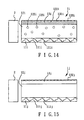
FIG. 14 shows schematically a tenth embodiment of the uniform reflective light-guide apparatus in accordance with the present invention;
FIG. 15 shows schematically an eleventh embodiment of the uniform reflective light-guide apparatus in accordance with the present invention;
FIG. 16 is a flowchart of a co-extrusion process to manufacture the uniform reflective light-guide apparatus in accordance with the present invention;
FIG. 17 shows a block diagram for the co-extrusion process of FIG. 16;
FIG. 18 shows a block diagram for a process to form a coarse surface on the light-exiting surface in accordance with the present invention;
FIG. 19 shows an angle-to-photo intensity plot for the light-guide apparatus in accordance with the present invention; and
FIG. 20 shows schematically an embodiment of an LED display having the uniform reflective light-guide apparatus in accordance with the present invention.
DESCRIPTION OF THE PREFERRED EMBODIMENT
The invention disclosed herein is directed to a uniform reflective light-guide apparatus, a backlight module having the same light-guide apparatus, and an LCD display having the same light-guide apparatus. In the following description, numerous details are set forth in order to provide a thorough understanding of the present invention. It will be appreciated by one skilled in the art that variations of these specific details are possible while still achieving the results of the present invention. In other instance, well-known components are not described in detail in order not to unnecessarily obscure the present invention.
To better and clearly describe the uniform reflective light-guide apparatus according to the present invention and the backlight module as well as the LCD display applying this light-guide apparatus, following descriptions will be detailed by accompanying figures.
(I) Briefing of the Present Invention on the Flat Plate of the Guide Light Apparatus:
As shown in FIG. 4, a first embodiment of the uniform reflective light-guide apparatus according to the present invention is schematically present. The uniform reflective light-guide apparatus 1, particularly an all-in-one light-guide apparatus, is to include internal diffusing particles and to apply an integral process to make the single apparatus to include functions of light-distributing, light-guiding and light-reflecting. Such an apparatus can be used with any edge-type light source. The main body of the light-guide apparatus mainly includes:
a reflective layer 11; and
a light-guiding layer 12 capable of homogenizing or distributing uniformly the lights inside the layer 12.
As shown in FIG. 4, the main body of the light-guide apparatus 1 can be a simple one-piece double-layer plate which can be produced by a co-extrusion process.
(II) Briefing of the Present Invention on the Reflective Layer 11 (the Lower Layer):
In the present invention, one of many important design concepts of the uniform reflective light-guide apparatus 1 is to apply an edge light source 2 to replace the conventional net-type light source. Also, the reflective layer 11 is added to replace the conventional reflective plate. By applying the diffusing particles in the light-guiding layer 12, the line or point light source can be homogenized and transformed into a surface light source, such that the light-guide apparatus 1 can thus have multiple functions in light reflection, light-guiding and light distribution.
By providing the aforesaid change, a substantial improvement in light loss can be gained by removing the reflective plate. Namely, in the present invention, the technique of including as the same plate a reflective layer 11 bottom to the light-guiding layer 12 capable of light distribution, as shown in FIG. 5, can wipe out the air spacing between the reflective layer 11 and the light-guiding layer 12, by compared to that shown in FIG. 2. Upon such an arrangement, the light utilization efficiency of the light-guide apparatus 1 of the present invention can be increased. Also, for the reflective layer 11 is capable of light reflection and light-guiding, the light loss thereof can be reduced to no more than 4%. Further, due to the manufacturing process for the light-guide apparatus 1 in accordance with the present invention is simplified, the membrane-adhering process, the process for producing the backlight module and the overall cost can be substantially reduced.
In the present invention, a preferred embodiment of the reflective layer 11 for the light-guide apparatus 1 can include the following features.
(1) The reflective layer 11 is produced by mixing two plastics with different refraction indexes, or by adding a predetermined amount of reflective particles into the matrix or plastics of the reflective layer 11.
(2) In the case that two plastics with different refraction indexes are used to form the base matrix of the reflective layer, the mixture rate can be a ratio of 7:3.
(3) In the case that the reflective particles 111 are introduced into the reflective layer 11, the refraction index for the reflective particle 111 can be ranged from 2.2˜3.2, and the weight proportion of the reflective particles 111 can be less than 0.5%.
(4) The granular size of the reflective particles 111 can be ranged between 1-100 μm, preferable between 4-50 μm.
(5) The refraction index for the base matrix or plastics of the reflective layer 11 is ranged between 1.6-2.5.
(6) The difference in refraction index (Δn) between the reflective layer 11 and the light-guiding layer is ranged between 0.05-1.
(III) Briefing of the Present Invention on the Light-Guiding Layer 12 (the Upper Layer):
In the present invention, a preferred embodiment of the uniform reflective light-guide apparatus 1 can add a plurality of micro diffusing particles into the light-guiding layer 12 so as to transform the original line or point light source into a surface light source. Upon such an arrangement, the performance in the light distribution can be improved, and the light utilization efficiency can be increased by utilizing materials with different refraction indexes.
In the present invention, a preferred embodiment of the light-guiding layer 12 for the light-guide apparatus 1 can include the following features.
(1) The light-guiding layer 12 is added by a small amount of diffusing particles or is matt finished at the light-exiting surface 121.
(2) The difference in refraction index (Δn) between the diffusing particles and the light-guiding layer 12 is limited to 0.04<Δn<0.1.
(3) The granular size of the diffusing particles is ranged between 2 μm˜10 μm.
(4) The roughness (Ra) of the surface (the light-exiting surface 121) of the light-guiding layer 12 is defined as 1 μm<Ra<6 μm, so as to enhance the luminance and uniformity.
(5) The refraction index for the base matrix or plastics of the light-guiding layer is ranged between 1.42-1.63.
(IV) Briefing of the Present Invention on the Relationship Between the Light-Guiding Efficiency and the Thickness of the Light-Guiding Layer 12 (the Lower Layer):
In the present invention, a preferred thickness range of the reflective layer 11 can be obtained by evaluating the relation between the thickness of the reflective layer 11 and the amount of incident rays. Preferably, the thickness of the reflective layer 11 shall be less than 1/10 of the total thickness of the plate body (including the light-guiding layer 12 and the reflective layer 11.
(V) Briefing of the Present Invention on the Relationship Among Thickness, Concentration and Uniformity of the Light-Guiding Layer 12 (the Upper Layer):
In the present invention, relationship among thickness, concentration and uniformity for a preferred embodiment of the light-guiding layer 12 capable of light-distribution or homogenization may have the following features.
(1) The light-guiding layer 12 is added by a small amount of diffusing particles to resolve problems in line defects and ill-uniformity.
(2) The smaller the granular size of the diffusing particle is, the narrower the identical penetration distribution is.
(3) When the granular size of the diffusing particle becomes larger, the identical penetration distribution will become broader.
(4) The difference in refraction index, the granular size and the corresponding concentration of the diffusing particles in the light-guiding layer 12 are all control parameters to the aforesaid relationship.
In the present invention, problems of the light-guide apparatus 1 in line defects and ill uniformity can be resolved by introducing or doping a small amount of diffusing particles into the light-guiding layer 12. Also, thereby, the light utilization rate of the apparatus 1 can be enhanced. When the difference of the refraction rates between the diffusing particles and the plastic matrix of the light-guiding layer 12 is limited to 0.04<Δn<0.1, a higher light penetration rate can be maintained.
In addition, the thickness of the light-guiding layer 12 and the concentration of the diffusing particles are highly related to the luminance and uniformity of the apparatus 1.
In the present invention, following structures of the apparatus 1 are related to performance of the light-guiding layer 12 in roughness and luminance.
(1) The roughness of the surface (light-exiting surface 121) of the light-guiding layer 12 is in favor to the luminance of the light-guiding layer 12.
(2) The distribution in roughness of the surface (light-exiting surface 121) of the light-guiding layer 12 is varied with the concentration of the diffusing particles.
In summary, the roughness (Ra) on the surface (light-exiting surface 121) of the light-guiding layer 12 has the following merits: (1) to increase the luminance of the light-guiding layer; (2) to resolve the line defects; (3) to enhance the uniformity.
In the present invention, a better luminance (L) can be obtained while the roughness (Ra) on the surface (light-exiting surface 121) of the light-guiding layer 12 is limited to the range of 1 μm to 6 μm.
(VI) Briefing of the Present Invention on the Three-Layer Laminating Structure of the Uniform Reflective Light-Guide Apparatus 1 a:
Referring now to FIG. 6, the uniform reflective light-guide apparatus 1 a is shown to have a three-layer laminating structure. The laminating structure is manufactured as a whole into a unique piece by a co-extrusion process. The main body of the uniform reflective light-guide apparatus 1 a includes:
a reflective layer 11 a (the lower layer);
a light-guiding layer 12 a (the middle layer); and
a light-distributing layer 13 a (the upper layer).
By applying the reflective particles 111 a in the light-reflecting layer 11 a, the line or point light source can be homogenized and transformed into a surface light source, by which the usage of the conventional net-type light source and the reflective plate can be replaced. Also, the light-guide apparatus 1 a can have multiple functions in light reflection, light-guiding and light distribution.
By providing the present invention, the aforesaid air spacing as shown in FIG. 2 in the prior design to cause majorly the light loss problem can be successfully removed. In the present invention, the reflective layer 11 a is added, as the same plate from the same co-extrusion process, to the bottom of the light-guiding layer 12 a, can totally avoid the existence of possible air spacing between the reflective layer 11 a and the light-guiding layer 12 a.
For no air spacing exists between the reflective layer 11 a and the light-guiding layer 12 a in accordance with the present invention, the light utilization efficiency of the light-guide apparatus 1 a can be increased, and the light loss thereof can be reduced; by compared to the apparatus of FIG. 2. Further, due to the manufacturing process for the light-guide apparatus 1 a in accordance with the present invention is simplified, the membrane-adhering process, the process for producing the backlight module and the overall cost can be substantially reduced.
Preferably, the reflective layer 11 a of the light-guide apparatus 1 a in accordance with the present invention is embodied as follows:
(1) Mixing two plastics with different refraction indexes, or adding a predetermined amount of reflective particles 11 a;
(2) Keeping the mixture rate of these two plastics at 7:3;
(3) Having the refraction index for the reflective particle 111 a can be ranged from 2.2˜3.2, and the weight proportion of the reflective particles 111 a less than 0.5%;
(4) Having the granular size of the reflective particles 111 a ranged between 1-100 μm, preferable between 4-50 μm;
(5) Having the refraction index of the reflective layer 11 a ranged between 1.6-2.5; and
(6) Having the difference in refraction index (Δn) between the reflective layer 11 a and the light-distributing layer 13 a ranged between 0.05-1.
Upon such an arrangement, a better light reflection rate and a less light loss can be obtained.
In the present invention as shown in FIG. 6, the light-distributing layer 13 a is located to a side (the top side in the figure) of the light-guiding layer 12 a, by opposing to the location of the light-reflective layer 11 a. The diffusing particles 13 a in the light-distributing layer 13 a can transform line or point light sources into a surface light source, such that the light distribution can be uniform. By providing different refraction indexes to the same plate body of the apparatus 1 a, the light utilization efficiency can thus be substantially enhanced
According to the preferred embodiment of the apparatus 1 a, the light-distributing layer 13 a can be embodied as follows:
(1) Adding a small amount of diffusing particles 131 a, or processing matt treatment upon the light-exiting surface;
(2) Having a difference of the refraction indexes between the diffusing particles 131 a and the matrix plastics of the light-distributing layer 13 a limited by 0.04<Δn<0.1;
(3) Having the granular size of the diffusing particles ranged between 2 μm˜10 μm;
(4) Having the roughness (Ra) of the light-exiting surface 132 a of the light-distributing layer 13 a limited by 1 μm<Ra<6 μm, so as to increase the luminance and the uniformity; and
(5) Having the refraction index of the matrix plastics for the light-distributing layer 13 a ranged between 1.42-1.63.
In the apparatus 1 a of the present invention, the relationship among thickness, concentration and uniformity of the light-distributing layer 13 a can be embodied as follows:
(1) Adding a small amount of diffusing particles 131 a to resolve problems in line defects and ill-uniformity;
(2) Making narrower the identical penetration distribution by making smaller the granular size of the diffusing particles;
(3) Making broader the identical penetration distribution by enlarging the granular size of the diffusing particles; and
(4) Varying the performance by changing the difference in refraction index, the granular size and the corresponding concentration of the diffusing particles 131 a.
In one embodiment of the light-guiding layer 12 a (the middle layer) of the apparatus 1 a in accordance with the present invention, a small amount of diffusing particles can be added to resolve the line defects and ill-uniformity of the light-guiding layer 12 a. Also, thereby, the light utilization efficiency can be substantially increased. When 0.04<Δn<0.1 between the diffusing particles and the matrix plastics of the light-guiding layer 12 a, a better light penetration rate can be maintained.
In addition, the thickness ratio of the light-distributing layer 13 a to the light-guiding layer 12 a, the concentration of the diffusing particles 131 a in the light-distributing layer 13 a, the luminance and the light uniformity are correlated.
In the preferred embodiment of the apparatus 1 a in accordance with the present invention, the shape of the light-guiding layer 12 a and the roughness of the light-exiting surface 132 a of the light-distributing layer 13 a can be embodied as follows.
(1) When the surface of the light-distributing layer 13 a is uneven, it is positive in enhancing the luminance of the light-guiding plate.
(2) Surface roughness of the light-exiting surface 132 a of the light-distributing layer 13 a varies with the concentration of the reflective particles 111 a in the reflective layer 11 a.
In the present invention, the merits of the surface roughness (Ra) of the light-exiting surface 132 a of the light-distributing layer 13 a are: (1) to increase the luminance of the light-guiding plate; (2) to resolve the problem of line defects; and (3) to enhance the uniformity.
Hence, in the present invention, the luminance (L) at the light-exiting surface 132 a of the light-distributing layer 13 a in the light-guide apparatus 1 a can be better present at the condition of having a surface roughness (Ra) between 1 μm and 6 μm.
(VII) Briefing of the Present Invention on Various Embodiments of the Uniform Reflective Light-Guide Apparatus:
The first embodiment: as shown in FIG. 4, the main body of the uniform reflective light-guide apparatus 1 is manufactured as a unique piece to form a double-layer plate structure having a light-guiding layer 12 capable of light-distributing and a reflective layer 11. The top surface (the light-exiting surface 121) of the light-guiding layer 12 can be made as a matted surface with a controllable transmittance. The reflective layer 11 located under the light-guiding layer 12 can include reflective particles 111. The upper and the lower surfaces of the reflective layer 11 are both smooth surfaces.
The second embodiment: as shown in FIG. 7, the main body of the uniform reflective light-guide apparatus 1 b is manufactured as a unique piece to form a double-layer plate structure having a light-guiding layer 12 b capable of light-distributing and a reflective layer 11 b. The light-guiding layer 12 b as the upper layer can have diffusing particles 122 b. The top surface (the light-exiting surface 121 b) of the light-guiding layer 12 b can be made as a matted surface with a controllable transmittance. The reflective layer 11 b located under the light-guiding layer 12 b can include reflective particles 111 b. The upper and the lower surfaces of the reflective layer 11 b are both smooth surfaces.
The third embodiment: as shown in FIG. 6, the main body of the uniform reflective light-guide apparatus 1 a is manufactured as a unique piece to form a triple-layer plate structure having an upper light-distributing layer 13 a further having diffusing particles 131 a. The top surface (the light-exiting surface 132 a) of the light-distributing layer 1 a can be made as a matted surface with a controllable transmittance. The middle light-guiding layer 12 a made of a transparent light-guiding material can have no diffusing particles. The lower reflective layer 11 b can include reflective particles 111 a. The upper and the lower surfaces of the reflective layer 11 b are both smooth surfaces.
The fourth embodiment: as shown in FIG. 8, the main body of the uniform reflective light-guide apparatus 1 c is manufactured as a unique piece to form a triple-layer plate structure having an upper light-distributing layer 13 c, a middle light-guiding layer 12 c and a lower reflective layer 11 c. The light-distributing layer 13 c may have no diffusing particles, but has a top surface (the light-exiting surface 132 c) formed as a matted surface with a controllable transmittance. The middle light-guiding layer 12 c can have diffusing particles 122 c. The lower reflective layer 11 c can include reflective particles 111 c. The upper and the lower surfaces of the reflective layer 11 c are both smooth surfaces.
The fifth embodiment: as shown in FIG. 9, the main body of the uniform reflective light-guide apparatus 1 d is manufactured as a unique piece to form a triple-layer plate structure having an upper light-distributing layer 13 d, a middle light-guiding layer 12 d and a lower reflective layer 11 d. The upper light-distributing layer 13 d may have diffusing particles 131 d, and has a top surface (the light-exiting surface 132 d) formed as a matted surface with a controllable transmittance. The middle light-guiding layer 12 d can have diffusing particles 122 d. The lower reflective layer 11 d can include reflective particles 111 d. The upper and the lower surfaces of the reflective layer 11 d are both smooth surfaces.
The sixth embodiment: as shown in FIG. 10, the main body of the uniform reflective light-guide apparatus 1 e is manufactured as a unique piece to form a triple-layer plate structure having an upper light-distributing layer 13 e, a middle light-guiding layer 12 e and a lower reflective layer 11 e. The upper light-distributing layer 13 e does not include any diffusing particle, but has a top surface (the light-exiting surface 132 e) formed as a matted surface with a controllable transmittance. The middle light-guiding layer 12 e does not include any diffusing particle, either. The lower reflective layer 11 e can include reflective particles 111 e. The upper and the lower surfaces of the reflective layer 11 e are both smooth surfaces. In this embodiment, matrix of the light-distributing layer 13 e and that of the light-guiding layer 12 e do not have the same refraction index. It is noted that if the aforesaid two refraction indexes are the same in the sixth embodiment, the foregoing first embodiment in FIG. 4 is actually repeated.
The seventh embodiment: as shown in FIG. 11, the main body of the uniform reflective light-guide apparatus 1 f is manufactured as a unique piece to form a triple-layer plate structure having an upper light-distributing layer 13 f, a middle light-guiding layer 12 f and a lower reflective layer 11 f. The upper light-distributing layer 13 f may have no diffusing particles, but has a top surface (the light-exiting surface 1320 formed as a rough surface. The middle light-guiding layer 12 f can have diffusing particles 122 f. The lower reflective layer 11 f can include reflective particles 111 f. The upper and the lower surfaces of the reflective layer 11 f are both smooth surfaces. The upper surface (i.e. the light-exiting surface 132 f) of the light-distributing layer 13 f can be made as a coarse surface with controllable roughness for regulating the light uniformity of the apparatus 1 f and also enhancing the apparatus luminance (so as to replace the conventional design in printed net nodes). Further, the coarse surface can lessen the adhering phenomenon between the apparatus 1 f and the optical membrane (not shown in the figure) which is a conventional design to paste onto the light-distributing layer 13 f. By compared to FIG. 2, there is no air spacing to exist between any two of the light-distributing layer 13 f, the light-guiding layer 12 f and the reflective layer 11 f of the apparatus 1 f of the present invention. Upon such an arrangement, the light-guide apparatus 1 f capable of light reflection and distribution can enhance the light utilization efficiency, reduce effectively the light loss resulted from Fresnel Loss, and need no more the reflection plate. By applying the light-guide apparatus 1 f to a backlight module, the corresponding structuring can be simplified and the related module costing can be substantially reduced.
The eighth embodiment: as shown in FIG. 12, the main body of the uniform reflective light-guide apparatus 1 g is manufactured as a unique piece by a co-extrusion process to form a triple-layer plate structure having an upper light-distributing layer 13 g, a middle light-guiding layer 12 g and a lower reflective layer 11 g. The upper light-distributing layer 13 g includes diffusing particles 131 g (to achieve functions in light homogeneity and defect waiving), and has a top surface (the light-exiting surface 132 g) formed as a coarse surface with controllable roughness. The middle light-guiding layer 12 g does not include any diffusing particle. The lower reflective layer 11 g can include reflective particles 111 g. The upper and the lower surfaces of the reflective layer 11 g are both smooth surfaces.
The ninth embodiment: as shown in FIG. 13, the main body of the uniform reflective light-guide apparatus 1 h is manufactured as a unique piece by a co-extrusion process to form a double-layer plate structure having a light-guiding layer 12 h capable of light-distributing and a reflective layer 11 h. The light-guiding layer 12 h as the upper layer can have diffusing particles 122 h, and the top surface (the light-exiting surface 121 h) can be a coarse surface with controllable roughness. The reflective layer 11 h located under the light-guiding layer 12 h can include reflective particles 111 h. The upper and the lower surfaces of the reflective layer 11 h are both smooth surfaces.
The tenth embodiment: as shown in FIG. 14, the main body of the uniform reflective light-guide apparatus 1 i is manufactured as a unique piece by a co-extrusion process to form a triple-layer plate structure having an upper light-distributing layer 13 i, a middle light-guiding layer 12 i and a lower reflective layer 11 i. The upper light-distributing layer 13 i may have diffusing particles 131 i, and has a top surface (the light-exiting surface 132 i) formed as a coarse surface with controllable roughness. The middle light-guiding layer 12 i can have diffusing particles 122 i. The lower reflective layer 11 i can include reflective particles 111 i. The upper and the lower surfaces of the reflective layer 11 i are both smooth surfaces. In this embodiment, matrix of the light-distributing layer 13 i and that of the light-guiding layer 12 i do not have the same refraction index. It is noted that if the aforesaid two refraction indexes are the same and the diffusing particles 131 i and 122 i are also the same in this embodiment, the foregoing embodiment in FIG. 13 is substantially repeated.
The eleventh embodiment: as shown in FIG. 15, the main body of the uniform reflective light-guide apparatus 1 j is manufactured as a unique piece by a co-extrusion process to form a triple-layer plate structure having an upper light-distributing layer 13 j, a middle light-guiding layer 12 j and a lower reflective layer 11 j. The upper light-distributing layer 13 j may have no diffusing particles, but has a top surface (the light-exiting surface 132 j) formed as a coarse surface with controllable roughness. The middle light-guiding layer 12 j can have no diffusing particles. The lower reflective layer 11 j can include reflective particles 111 j. The upper and the lower surfaces of the reflective layer 11 j are both smooth surfaces.
Referring now to FIGS. 16 and 17, an embodiment of a co-extrusion process for manufacturing the uniform reflective light-guide apparatus in accordance with the present invention is shown in a flowchart and a schematic block diagram, respectively. The triple-layer laminating structure shown in FIG. 9 is typically used to explain how this co-extrusion process can produce the light-guide apparatus 1 d as a unique piece. First of all, prepare the matrix plastics for forming the reflective layer 11 d and a appropriate amount of reflective particles 111 d in a material tank 21 of a secondary extrusion machine 1. On the other hand, prepare the matrix plastics for forming the light-guiding layer 12 d and a proper amount of diffusing particles 122 d with various granular sizes and various refraction indexes in a material tank 22 of a primary extrusion machine. At the same time, prepare the matrix plastics for forming the light-distributing layer 13 d and a proper amount of diffusing particles 131 d with various granular sizes and various refraction indexes in a material tank 23 of another secondary extrusion machine 2. The matrix plastics for the light-guiding layer 12 d and that for the light-distributing layer 13 d can be the same. Also, Materials for the diffusing particles 122 d and 131 d can be the same as well. Then, materials in the material tanks 21,22 and 23 are further being screw extrusion mixed (24), respectively, before being sent to be extruded into respective layers of the T die 25. The materials mixed with corresponding particles or beads are simultaneously extruded out of the T Die 25 as a laminating form and are further rolled to form consequently by the rollers R1, R2 and R3. Then, the “all-in-one” main plate body of the light-guide apparatus 1 d are formed. By compared to the conventional coating process which coats a reflective layer onto the light-guiding layer, the “all-in-one” co-extrusion process provided by the present invention can be more easily as an advanced manufacturing process.
Referring now to FIG. 18, a block diagram for a process to form a coarse surface on the light-exiting surface in accordance with the present invention is shown. In the present invention, the coarse surface can be located to the light-exiting surface of a light-distributing layer (for the triple-layer laminating structure) or a light-guiding layer capable of light-distributing (for a double-layer laminating structure). The surface roughness can be controlled by adjusting the sandblasting apparatus 31 by regulating the sandblasting pressure p, sandblasting velocity v, and the distant d between the sandblasting nozzle 32 and the roller surface 33. The surface roughness of the coarse surface will affect the electrostatic adhesion between the light-exiting surface of the light-guide apparatus of the present invention and the optical members, and the light uniformity of the light-guide apparatus. Table 2 lists a typical example.
| TABLE 2 |
| |
| Adhesion relation between surface roughness of coarse |
| surfaces (light-exiting surfaces) and optical members |
| |
Example A |
Example B |
Example C |
Example D |
Example E |
| |
| d (mm) |
220 |
220 |
220 |
220 |
220 |
| p (MPa) |
0.38 |
0.38 |
0.38 |
0.38 |
0.38 |
| v (m/min) |
15 |
12 |
8 |
4 |
1 |
| Surface |
0.07 |
0.46 |
1.35 |
2.21 |
2.52 |
| roughness |
|
|
|
|
|
| Ra (μm) |
|
|
|
|
|
| Adhesion |
Easy |
Fair |
Difficult |
Difficult |
Difficult |
| of optical |
|
|
|
|
|
| members |
| |
In Table 2, when the surface roughness (Ra) of the light-exiting surface of the apparatus of the present invention is less than 0.46 μm, the adhesion between the light-exiting surface and the optical member will become easier and thus scratches in between become highly possible. When Ra is greater than 2.21 μm, the light output at the light-exiting surface will increase but only to decrease the light uniformity of the apparatus. Further, when Ra is greater than 6 μm, the lighting quality of the apparatus might be hard to pass the manufacturer's QC. Therefore, in the present invention, the surface roughness of the coarse surface formed on the light-exiting surface of the light-guide apparatus in accordance with the present invention is limited to a range between 0.46 μm and 2.21 μm, preferably the range between 1 μm and 2.21 μm.
In the present invention, the plastics, the matrix plastics, or say the base matrix for the light-distributing layer, the light-guiding layer and the reflective layer can be selected from, but not limited to, appropriate plastics available in the market, such as polymethylmethacrylate (PMMA), polycarbonate (PC), polyethylene terephthalate (PET), MS and so on. The diffusing particles for the light-distributing layer and the light-guiding layer can be also selected from, but not limited to, appropriate plastics particles available in the market, such as PMMA particles, PC particles, PET particles, MS particles and so on. Similarly, the reflective particles can be selected from, but not limited to, appropriate materials available in the market, such as SiO2 particles, TiO2 particles, PMMA particles and so on.
Regards the co-extrusion process for producing the light-guide apparatus of the present invention, various advantages can be obtained, such as the unique-piece plate body, high light utilization efficiency, low light loss, no need of additional reflective plate, simple structuring, less expanding on the backlight module, less adhesion to the optical members, and plenty optical merits in light uniformity, luminance and user comfort.
Referring now to FIG. 19, an angle-to-photo intensity plot for the light-guide apparatus in accordance with the present invention is shown. The X axis of the plot is the angle axis ranged from 0 to 90 degrees, and the Y axis of the plot is the axis for photo intensity. Have the apparatus 1 b of FIG. 7 as an example. The co-extrusion double-layer plate body for the light-guide apparatus 1 b of the present invention includes the upper light-guiding layer 12 b capable of light distributing and added by diffusing particles with a thickness t1, and the lower reflective layer 11 b added by reflective particles, with a thickness t2. The light-introducing surface 15 is located laterally to the light-guiding layer 12 b of the apparatus 1 b. The edge light source 2 for emitting light rays 20 is located close to the light-introducing surface 15. The light rays 20 are introduced to the light-guiding layer 12 b of the apparatus 1 b through the light-introducing surface 15. The interface between the light-guiding layer 12 b and the reflective layer 11 b is played as a reflective surface 112. The light-exiting surface 121 b is located at the top surface of the light-guiding layer 12 b, by opposing to the reflective surface 112 with respect to the light-guiding layer 12 b. The light-introducing surface 15 is perpendicular to the light-exiting surface 121 b. At an arbitrary point of the light-exiting surface 121 b, a normal line N can be defined to be perpendicular to the light-exiting surface. The angle at this arbitrary point between the normal line N and the incident ray is defined as the angle θ. When a light ray 20 hits the reflective surface 112 from the light-guiding layer 12 b, if the incident angle is not zero, i.e. the light ray 20 not perpendicular to the reflective surface 112, the light ray 20 will be sent back to the light-guiding layer 12 b by the reflective surface 112. On the other hand, when a light ray 20 hits the light-exiting surface 121 b from the light-guiding layer 12 b, the light ray 20 might be reflected back or allowed to leave, either which is dependent on the angle θ between the incident light ray and the normal line N.
As shown in FIG. 19, a detector 123 can be located to the light-guiding layer 12 b by being close to the light-exiting surface 121 b. The detector 123 is to detect the photo pattern of light rays leaving the light-exiting surface 121 b, and the photo pattern results can be plotted into the plot of FIG. 19, in terms of photo intensity to the angle θ. In the figure, L1, L2, area A, area B and area C are defined as follows.
Perpendicular line L1: the line defining the critical angle θc of the material for the light-guiding layer 12 b, in which θc=sin−1(1/n). In this embodiment, the refraction index n for the light-guiding layer 12 b is 1.58. Then, θc=39.26° (about 40°). Therefore, in FIG. 19, the angle for rising L1 is almost at the angle 40°.
Perpendicular line L2: the line defining an angle by adding 20 degrees to the critical angle θc. Therefore, in FIG. 19, the angle for rising L2 is almost at the angle 60°.
Area A (light-guiding area): indicating the light ray having a larger θ. In FIG. 19, the area A is the area defined or enclosed by the light curve in the plot, the L2 and the X axis.
Area B (indirect light-exiting area): indicating the light rays having angles between θc and θc+20°. These light rays are reflected by the light-exiting surface and may come back to leave the light-guiding layer 12 by the help of the diffusing particles (or say, beads) in the light-guiding layer 12 b. In FIG. 19, area B is defined by the light curve, the L1, the L2 and the X axis.
Area C (direct light-exiting area): indicating the light rays having angles less than θc. These light rays will leave the light-guiding layer 12 b directly through the light-exiting surface 121 b. in FIG. 19, area C is defined by the light curve, the L1 and the X axis. As shown in FIG. 19, area C is zero when the light-guiding layer does not include any bead.
In the present invention, the light-guide coefficient (LGC) is defined by LGC=A/(B+C).
The larger the LGC is, the better light-guiding performance the light-guiding layer has. When a small LGC is met, it implies that the light-guiding layer will retain most of the lights there inside. High value in the light-guiding performance implies worse luminance in the apparatus. On the other hand, if the LGC is small, high luminance will be found at a side of the light-exiting surface, in which the side is close to the light-introducing surface.
In the present embodiment for the double-layer laminating structure, t1 indicates the thickness of the light-guiding layer 12 b capable of light distributing. However, for the triple-layer laminating structure having an independent light-distributing layer, t1 is the thickness sum of the light-distributing layer and the light-guiding layer, while t2 herein is the thickness of the reflective layer.
According to various embodiments from FIG. 4 to FIG. 15 of the present invention, the co-extrusion process do contribute a lot to the structuring and related performance by eliminating the air spacing between layers. Further, if the following two criteria are satisfied, optical performance in luminance and uniformity can be better ensured.
(1) 0.001<(t2/t1)<0.111; and
(2) 2.07<LGC<4.23.
If (t2/t1) is less than 0.001, the reflection rate would be decreased for the thickness in the reflective layer is too small, such that a greater light loss would be met. If (t2/t1)>0.111, the thin light-guiding layer will make worse the light distribution in the apparatus. When LGC<2.07, the light-retaining rate of the light-guiding layer would be too good to damage the uniformity and thus the user comfort. When LGC>4.23, the light-retaining rate of the light-guiding layer would be too small to reduce the luminance.
In order to have the LGC be controlled within 2.07˜4.23, following parameters may be helpful.
From FIG. 19, it is noted that when the light-guiding layer is free of beads, the light-retaining ability will be reduced, but the ability in light-guiding will be improved; such that the exiting lights would be limited in a localized manner. Therefore, if the light-guiding layer is added by a proper amount and a proper granular size formulation of beads, an optimal optical performance in light guiding and retaining can be obtained. To better understand how the concentration and the granular size of the beads can affect the LGC value of the apparatus of the present invention, various granular sizes, concentrations and refraction indexes are introduced to simulate the aforesaid criteria for the embodiment setup shown in FIG. 19. The results are listed in the following Table 3, Table 4 and Table 5.
| TABLE 3 |
| |
| Relationship between beads concentration and |
| LGC at the granular size of beads being 2 μm |
| Δn |
0.02 |
0.04 |
0.06 |
0.08 |
0.10 |
0.12 |
| |
| Beads concentration 0.0001 wt % |
| A |
208498.01 |
207879.91 |
208735.26 |
209104.37 |
208264.72 |
208867.13 |
| B + C |
51324.80 |
51636.67 |
51026.89 |
50997.63 |
50771.04 |
51353.73 |
| LGC |
4.06 |
4.03 |
4.09 |
4.10 |
4.10 |
4.07 |
| Beads concentration 0.002 wt % |
| A |
208437.12 |
210590.23 |
210011.17 |
209334.61 |
210016.40 |
209428.39 |
| B + C |
51766.93 |
50834.07 |
51113.76 |
52110.23 |
51520.57 |
51416.40 |
| LGC |
4.03 |
4.14 |
4.11 |
4.02 |
4.08 |
4.07 |
| Beads concentration 0.05 wt % |
| A |
211325.54 |
210338.55 |
206829.33 |
202062.28 |
195007.11 |
186715.50 |
| B + C |
51561.46 |
52193.76 |
53707.08 |
55446.51 |
58937.18 |
62006.60 |
| LGC |
4.10 |
4.03 |
3.85 |
3.64 |
3.31 |
3.01 |
| Beads concentration 0.2 wt % |
| A |
211310.68 |
200821.40 |
187478.11 |
169020.76 |
155730.88 |
148640.25 |
| B + C |
52697.47 |
56800.31 |
61649.31 |
68791.45 |
68945.72 |
69431.03 |
| LGC |
4.01 |
3.54 |
3.04 |
2.46 |
2.26 |
2.14 |
| |
| TABLE 4 |
| |
| Relationship between beads concentration and |
| LGC at the granular size of beads being 6 μm |
| Δn |
0.02 |
0.04 |
0.06 |
0.08 |
0.10 |
0.12 |
| |
| Beads concentration 0.0001 wt % |
| A |
208371.06 |
208061.37 |
207466.43 |
208391.74 |
208565.21 |
208288.71 |
| B + C |
51349.88 |
50656.52 |
50817.76 |
51484.79 |
51175.75 |
51711.57 |
| LGC |
4.06 |
4.11 |
4.08 |
4.05 |
4.08 |
4.03 |
| Beads concentration 0.002 wt % |
| A |
209419.68 |
209793.86 |
210171.42 |
209341.85 |
211353.26 |
210570.89 |
| B + C |
52123.54 |
51249.90 |
51044.58 |
51003.34 |
51273.76 |
51728.06 |
| LGC |
4.02 |
4.09 |
4.12 |
4.10 |
4.12 |
4.07 |
| Beads concentration 0.05 wt % |
| A |
211223.55 |
209344.29 |
208811.13 |
204968.58 |
206007.14 |
202145.27 |
| B + C |
50973.60 |
51093.70 |
52745.58 |
52590.55 |
54850.59 |
54963.03 |
| LGC |
4.14 |
4.10 |
3.96 |
3.90 |
3.76 |
3.68 |
| Beads concentration 0.2 wt % |
| A |
210548.02 |
210604.38 |
202317.62 |
196428.65 |
183832.05 |
175748.16 |
| B + C |
51287.74 |
53305.66 |
54756.06 |
59955.21 |
62759.34 |
63918.79 |
| LGC |
4.11 |
3.95 |
3.69 |
3.28 |
2.93 |
2.75 |
| |
| TABLE 5 |
| |
| Relationship between beads concentration and |
| LGC at the granular size of beads being 10 μm |
| Δn |
0.02 |
0.04 |
0.06 |
0.08 |
0.10 |
0.12 |
| |
| Beads concentration 0.0001 wt % |
| A |
207699.87 |
207319.62 |
207805.80 |
209704.41 |
207954.00 |
208759.94 |
| B + C |
51876.95 |
51435.20 |
51022.44 |
51367.43 |
51088.77 |
50994.87 |
| LGC |
4.00 |
4.03 |
4.07 |
4.08 |
4.07 |
4.09 |
| Beads concentration 0.002 wt % |
| A |
208744.84 |
209090.01 |
210317.62 |
209756.59 |
208942.29 |
209406.64 |
| B + C |
51387.45 |
52279.72 |
51767.20 |
51445.50 |
51220.61 |
51898.92 |
| LGC |
4.06 |
4.00 |
4.06 |
4.08 |
4.08 |
4.03 |
| Beads concentration 0.05 wt % |
| A |
211517.72 |
209612.25 |
211047.21 |
209318.93 |
207945.61 |
204441.15 |
| B + C |
50787.01 |
50599.69 |
51987.83 |
53262.51 |
53207.72 |
55027.92 |
| LGC |
4.16 |
4.14 |
4.06 |
3.93 |
3.91 |
3.72 |
| Beads concentration 0.2 wt % |
| A |
209959.50 |
210219.32 |
206134.73 |
200487.73 |
191672.69 |
187296.05 |
| B + C |
51185.03 |
52108.09 |
55025.42 |
55691.66 |
58555.79 |
62352.86 |
| LGC |
4.10 |
4.03 |
3.75 |
3.60 |
3.27 |
3.00 |
| |
From the foregoing Table 3 to Table 5, when the beads concentration is less than 0.002 wt %, the refraction index has less influence on LGC. Therefore, the factor of the refraction index of the beads can be neglected in designing the coarse surface. When the beads concentration is greater than 0.05 wt %, the factor of the refraction index of the beads becomes important to the LGC. Therefore, the LGC, the light uniformity and the user comfort can be adjusted by altering the refraction index of the beads. Also, the granular size and the concentration can be used as well to adjust the LGC to locate within 2.07˜4.23.
Referring now to FIG. 20, an embodiment of an LED display having the uniform reflective light-guide apparatus in accordance with the present invention is schematically shown. The LCD display includes a backlight module and an LCD panel 57 located above the backlight module. The backlight module further includes an edge light source 2, at least an optical membrane 590 and the uniform reflective light-guide apparatus 1 d of the present invention shown in FIG. 9. The apparatus 1 d is a one-piece triple-layer laminating plate structure and includes a light-distributing layer 13 d, a light-guiding layer 12 d and a reflective layer 11 d. The light-introducing surface 15 d for introducing lights of the edge light source 2 into the light-guiding layer 12 d is defined laterally to the light-guiding layer 12 d. The reflective layer 11 d can reflect the incident light rays from the light-guiding layer 12 d back to the light-guiding layer 12 d. The light-exiting surface 132 d for allowing portion of lights to leave the light-guiding layer 12 d is located at the top surface of the light-distributing layer 13 d, and is perpendicular to the light-introducing surface 15 d. The optical membrane 590 is to cover the light-exiting surface 132 d so as to improve the user comfort and to enhance the light uniformity. The LCD panel 57 is located at a side of the optical membrane 590, which the side is far from the light-guiding layer 12 d.
While the present invention has been particularly shown and described with reference to a preferred embodiment, it will be understood by those skilled in the art that various changes in form and detail may be without departing from the spirit and scope of the present invention.