US8851561B2 - Convenient telescopic folding chair - Google Patents
Convenient telescopic folding chair Download PDFInfo
- Publication number
- US8851561B2 US8851561B2 US12/890,726 US89072610A US8851561B2 US 8851561 B2 US8851561 B2 US 8851561B2 US 89072610 A US89072610 A US 89072610A US 8851561 B2 US8851561 B2 US 8851561B2
- Authority
- US
- United States
- Prior art keywords
- cushion
- foot
- seat cushion
- front foot
- lateral sides
- Prior art date
- Legal status (The legal status is an assumption and is not a legal conclusion. Google has not performed a legal analysis and makes no representation as to the accuracy of the status listed.)
- Active
Links
Images


Classifications
-
- A—HUMAN NECESSITIES
- A47—FURNITURE; DOMESTIC ARTICLES OR APPLIANCES; COFFEE MILLS; SPICE MILLS; SUCTION CLEANERS IN GENERAL
- A47C—CHAIRS; SOFAS; BEDS
- A47C4/00—Foldable, collapsible or dismountable chairs
- A47C4/04—Folding chairs with inflexible seats
- A47C4/18—Folding chairs with inflexible seats having a frame made of metal
- A47C4/20—Folding chairs with inflexible seats having a frame made of metal with legs pivotably connected to seat or underframe
- A47C4/24—Folding chairs with inflexible seats having a frame made of metal with legs pivotably connected to seat or underframe with cross legs
-
- A—HUMAN NECESSITIES
- A47—FURNITURE; DOMESTIC ARTICLES OR APPLIANCES; COFFEE MILLS; SPICE MILLS; SUCTION CLEANERS IN GENERAL
- A47C—CHAIRS; SOFAS; BEDS
- A47C5/00—Chairs of special materials
- A47C5/04—Metal chairs, e.g. tubular
- A47C5/06—Special adaptation of seat upholstery or fabric for attachment to tubular chairs
Definitions
- the present invention relates to folding chair, and particular to a convenient telescopic folding chair having telescopic rods and seat cushion formed by a cushion inserted to a tube frame.
- Folding chairs are very popular in the market. Except the basic folding function, the durability, portability, and storage are also concerned by the user.
- Prior folding chair mostly consists of seat cushion formed by a wooden-base cushion framed by a closed metal frame.
- the punched metal seat plate or molded plastic seat plate are also commonly used in folding chairs.
- the closed metal frame around the cushion will confine the design of the seat of the chair, and the punched metal seat will cause higher cost for manufacturing.
- the molded plastic seat is concerned about its safety and bearing capability, enhancement of thickness and material will oppositely increase the weight and the waste of storage.
- the primary object of the present invention is to provide a convenient, space-saving, light, fine and durable folding chair.
- the present invention includes a front foot, back cushion, rear foot, seat cushion, and telescopic rods arranged between the rear foot and the seat cushion.
- the front foot pivots on the rear foot by connecting components.
- the back cushion is inserted into two ends of the front foot.
- the rear foot connects the seat cushion through two telescopic rods arranged to two ends of the rear foot.
- the seat cushion is further connected to the front foot through connecting components.
- the seat cushion includes a tube frame and a cushion. The cushion is fixed to the frame with two plugs formed to two lateral sides thereof inserting into two ends of the frame.
- FIG. 1 is a schematic view showing an embodiment of the present invention.
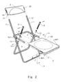
- FIG. 2 is an assembling view showing the embodiment in FIG. 1 .
- FIG. 3 is a schematic view showing another embodiment of the present invention.
- FIG. 4 is an assembling view showing the embodiment in FIG. 3 .
- FIG. 5 is an assembling view showing a seat cushion in FIG. 1 .
- FIG. 6 is an assembling view showing a seat cushion in FIG. 3 .
- FIG. 7 is a schematic view showing an embodiment of a front edge of the seat cushion of the present invention.
- FIGS. 1 and 3 two embodiments of convenient telescopic folding chair according to the present invention are illustrated.
- the embodiments both include front foot 1 , back cushion 2 , rear foot 3 , seat cushion 4 , and telescopic rods 5 arranged between two lateral sides of the seat cushion 4 and the two ends of the rear foot 3 .
- the front foot 1 pivots on the rear foot 3 through arranging holes 11 .
- Two retaining holes 12 are formed near to two ends of the front foot 1 respectively for receiving two spring-loaded pins 21 on two lateral sides of the back cushion 2 .
- Two plugs 22 are also formed to the two later sides of the back cushion 2 for being inserted into the two ends of the front foot 1 so that the back cushion 2 is fixed to the front foot 1 with the spring-loaded pins 21 being retained by the two retaining holes 12 .
- Two connecting plates 13 are arranged oppositely to predetermined locations of an inner surface of the front foot 1 .
- the connecting plate 13 has a through hole 131 for assembling the front foot 1 to a frame 41 of the seat cushion 4 .
- Two sleeves 31 are slid into two ends of the rear foot 3 for receiving the two telescopic rods 5 .
- the telescopic rod 5 is fixed to the two lateral sides of the frame 41 of the seat cushion 4 .
- the three connection points of the telescopic rod 5 to the seat cushion 4 , the front foot 1 to the seat cushion 4 , and the front foot 1 to the rear foot 3 form a triangle so as to provide an ideal support and a strong structure.
- the seat cushion 4 includes a tube frame 41 and a cushion 42 .
- a plug 421 is formed to two lateral sides of the cushion 42 respectively for being inserted into the two ends of the frame 41 so as to form the seat cushion 4 .
- the frame 41 sustains a rear and two lateral sides of the cushion 42 so as to provide a high bearing capability based on the supporting of the front and the rear foot. Without the frame 41 , the front side of the cushion 42 can be shaped smoothly or ergonomically as shown in FIG. 7 .
- FIGS. 3 , 4 , and 6 another embodiment of the present invention is illustrated.
- the front foot 1 pivots on the rear foot 3 through arranging holes 11 .
- Two retaining holes 12 are formed near to two ends of the front foot 1 for receiving two spring-loaded pins 21 on two lateral sides of the back cushion 2 .
- Two plugs 22 are also formed to the two later sides of the back cushion 2 for being inserted into the two ends of the front foot 1 so that the back cushion 2 is fixed to the front foot 1 with the spring-loaded pins 21 being retained by the two retaining holes 12 .
- Two connecting plates 13 are arranged to predetermined opposite locations of an inner surface of the front foot 1 .
- the connecting plate 13 has a through hole 131 for assembling the front foot 1 to a tube frame 41 of the seat cushion 4 .
- Two sleeves 31 are slid into two ends of the rear foot 3 for receiving the two telescopic rods 5 .
- the telescopic rod 5 is fixed to the two lateral sides of the frame 41 of the seat cushion 4 .
- the seat cushion 4 includes the tube frame 41 and a cushion 42 as shown in FIG. 6 .
- a plug 421 is formed to two lateral sides of the cushion 42 respectively for being inserted into the two ends of the frame 41 so as to form the seat cushion 4 .
- the frame 41 sustains a front and the two lateral sides of the cushion 42 so as to provide a high bearing capability based on the supporting of the front and the rear foot.
- the present invention is light and space-saving for its thin folded thickness.
- the ergonomic design will improve the appearance and comfort thereof as well as the quality, practicability, and economic benefit.
Landscapes
- Mattresses And Other Support Structures For Chairs And Beds (AREA)
Abstract
Description
Claims (1)
Priority Applications (1)
| Application Number | Priority Date | Filing Date | Title |
|---|---|---|---|
| US12/890,726 US8851561B2 (en) | 2010-09-27 | 2010-09-27 | Convenient telescopic folding chair |
Applications Claiming Priority (1)
| Application Number | Priority Date | Filing Date | Title |
|---|---|---|---|
| US12/890,726 US8851561B2 (en) | 2010-09-27 | 2010-09-27 | Convenient telescopic folding chair |
Publications (2)
| Publication Number | Publication Date |
|---|---|
| US20120074737A1 US20120074737A1 (en) | 2012-03-29 |
| US8851561B2 true US8851561B2 (en) | 2014-10-07 |
Family
ID=45869910
Family Applications (1)
| Application Number | Title | Priority Date | Filing Date |
|---|---|---|---|
| US12/890,726 Active US8851561B2 (en) | 2010-09-27 | 2010-09-27 | Convenient telescopic folding chair |
Country Status (1)
| Country | Link |
|---|---|
| US (1) | US8851561B2 (en) |
Cited By (8)
| Publication number | Priority date | Publication date | Assignee | Title |
|---|---|---|---|---|
| US20160242550A1 (en) * | 2015-02-21 | 2016-08-25 | Ben Alton Hammock | Chair Assembly |
| WO2018217838A1 (en) * | 2017-05-23 | 2018-11-29 | Yeti Coolers, Llc | Portable chair and methods of forming a portable chair |
| US10561249B2 (en) | 2017-05-23 | 2020-02-18 | Yeti Coolers, Llc | Portable chair and cup holder assembly |
| US10743670B2 (en) | 2017-05-23 | 2020-08-18 | Yeti Coolers, Llc | Portable chair and cup holder assembly |
| US10842278B2 (en) | 2018-08-10 | 2020-11-24 | Ogg Design, Inc. | Folding chair and method of assembly |
| US11197552B2 (en) * | 2019-07-08 | 2021-12-14 | Pro-Cord S.P.A. | Flexible backrest for a folding chair, and folding chair comprising this backrest |
| US20220142370A1 (en) * | 2019-01-31 | 2022-05-12 | Luca Fornasarig | Chair |
| US20240298801A1 (en) * | 2023-03-08 | 2024-09-12 | Lifetime Products, Inc. | Chair |
Families Citing this family (9)
| Publication number | Priority date | Publication date | Assignee | Title |
|---|---|---|---|---|
| USD801062S1 (en) * | 2016-07-27 | 2017-10-31 | Yu-Shan Lin | Folding chair |
| US10405662B2 (en) * | 2017-03-02 | 2019-09-10 | Rio Brands, Llc | Folding X-frame chair with extended backrest |
| USD1111509S1 (en) * | 2022-03-10 | 2026-02-10 | New-Tec Integration (Xiamen) Co., Ltd. | Folding chair |
| USD1111508S1 (en) * | 2022-03-10 | 2026-02-10 | New-Tec Integration (Xiamen) Co., Ltd. | Folding chair |
| JP3237551U (en) * | 2022-03-24 | 2022-05-20 | 慈溪市牧吉熊戸外用品有限公司 | Folding chair |
| USD1111510S1 (en) * | 2022-04-28 | 2026-02-10 | New-Tec Integration (Xiamen) Co., Ltd. | Children's chair |
| USD1121982S1 (en) * | 2022-06-28 | 2026-04-14 | Luhao Leng | Folding chair |
| USD1111511S1 (en) * | 2022-06-28 | 2026-02-10 | Luhao Leng | Folding chair |
| CN220988175U (en) * | 2023-10-27 | 2024-05-24 | 浙江泰普森实业集团有限公司 | Folding chair frame and folding chair |
Citations (11)
| Publication number | Priority date | Publication date | Assignee | Title |
|---|---|---|---|---|
| US6543842B2 (en) * | 2000-02-03 | 2003-04-08 | Lifetime Products, Inc. | Interference fit support bracket for a portable folding chair |
| US6612654B2 (en) * | 2002-01-04 | 2003-09-02 | Mity-Lite, Inc. | Chair with upholstered inserts |
| US6616223B1 (en) * | 2002-03-07 | 2003-09-09 | Maxchief Investments Ltd. | Foldable chair |
| US20030168894A1 (en) * | 2002-03-07 | 2003-09-11 | Wen-Shen Lin | Foldable chair |
| US6695411B2 (en) * | 2000-09-29 | 2004-02-24 | Xiamen New-Tech Jcc Co, Ltd. | Folding chair |
| US20040251718A1 (en) * | 2002-11-07 | 2004-12-16 | Jin Degen | Folding chair |
| US20050206202A1 (en) * | 2000-02-03 | 2005-09-22 | Winter David C | Folding chair with armests |
| US7080877B1 (en) * | 2004-10-29 | 2006-07-25 | Maxchief Investments, Ltd | Folding chair with sliding leg structure |
| US7513567B2 (en) * | 2006-05-03 | 2009-04-07 | Tsung-Chieh Huang | Foldable chair with pull rods |
| US20090146467A1 (en) * | 2007-12-06 | 2009-06-11 | Donald Waite | Chair |
| US8109564B2 (en) * | 2010-02-03 | 2012-02-07 | Mei Chuen Lin | Seat self-lifting device for portable chair |
-
2010
- 2010-09-27 US US12/890,726 patent/US8851561B2/en active Active
Patent Citations (15)
| Publication number | Priority date | Publication date | Assignee | Title |
|---|---|---|---|---|
| US6871906B2 (en) * | 2000-02-03 | 2005-03-29 | Lifetime Products, Inc. | Portable folding chair |
| US7014261B2 (en) * | 2000-02-03 | 2006-03-21 | Lifetime Products, Inc. | Portable folding chair |
| US6543842B2 (en) * | 2000-02-03 | 2003-04-08 | Lifetime Products, Inc. | Interference fit support bracket for a portable folding chair |
| US20050206202A1 (en) * | 2000-02-03 | 2005-09-22 | Winter David C | Folding chair with armests |
| US6695411B2 (en) * | 2000-09-29 | 2004-02-24 | Xiamen New-Tech Jcc Co, Ltd. | Folding chair |
| US6612654B2 (en) * | 2002-01-04 | 2003-09-02 | Mity-Lite, Inc. | Chair with upholstered inserts |
| US20030168894A1 (en) * | 2002-03-07 | 2003-09-11 | Wen-Shen Lin | Foldable chair |
| US20030168893A1 (en) * | 2002-03-07 | 2003-09-11 | Wen-Shen Lin | Foldable chair |
| US6616223B1 (en) * | 2002-03-07 | 2003-09-09 | Maxchief Investments Ltd. | Foldable chair |
| US20040251718A1 (en) * | 2002-11-07 | 2004-12-16 | Jin Degen | Folding chair |
| US7017986B2 (en) * | 2002-11-07 | 2006-03-28 | Lifetime Products, Inc. | Folding chair |
| US7080877B1 (en) * | 2004-10-29 | 2006-07-25 | Maxchief Investments, Ltd | Folding chair with sliding leg structure |
| US7513567B2 (en) * | 2006-05-03 | 2009-04-07 | Tsung-Chieh Huang | Foldable chair with pull rods |
| US20090146467A1 (en) * | 2007-12-06 | 2009-06-11 | Donald Waite | Chair |
| US8109564B2 (en) * | 2010-02-03 | 2012-02-07 | Mei Chuen Lin | Seat self-lifting device for portable chair |
Cited By (12)
| Publication number | Priority date | Publication date | Assignee | Title |
|---|---|---|---|---|
| US20160242550A1 (en) * | 2015-02-21 | 2016-08-25 | Ben Alton Hammock | Chair Assembly |
| WO2018217838A1 (en) * | 2017-05-23 | 2018-11-29 | Yeti Coolers, Llc | Portable chair and methods of forming a portable chair |
| US10194749B1 (en) | 2017-05-23 | 2019-02-05 | Yeti Coolers, Llc | Portable chair and methods of forming a portable chair |
| US10561249B2 (en) | 2017-05-23 | 2020-02-18 | Yeti Coolers, Llc | Portable chair and cup holder assembly |
| US10743670B2 (en) | 2017-05-23 | 2020-08-18 | Yeti Coolers, Llc | Portable chair and cup holder assembly |
| US10842278B2 (en) | 2018-08-10 | 2020-11-24 | Ogg Design, Inc. | Folding chair and method of assembly |
| US20220142370A1 (en) * | 2019-01-31 | 2022-05-12 | Luca Fornasarig | Chair |
| US11812864B2 (en) * | 2019-01-31 | 2023-11-14 | Luca Fornasarig | Chair |
| US11197552B2 (en) * | 2019-07-08 | 2021-12-14 | Pro-Cord S.P.A. | Flexible backrest for a folding chair, and folding chair comprising this backrest |
| US20240298801A1 (en) * | 2023-03-08 | 2024-09-12 | Lifetime Products, Inc. | Chair |
| US20240298800A1 (en) * | 2023-03-08 | 2024-09-12 | Lifetime Products, Inc. | Chair |
| US12564264B2 (en) * | 2023-03-08 | 2026-03-03 | Lifetime Products, Inc. | Chair |
Also Published As
| Publication number | Publication date |
|---|---|
| US20120074737A1 (en) | 2012-03-29 |
Similar Documents
| Publication | Publication Date | Title |
|---|---|---|
| US8851561B2 (en) | Convenient telescopic folding chair | |
| KR102283013B1 (en) | Portable chair | |
| USD930609S1 (en) | Mobile phone | |
| USD674799S1 (en) | Mobile terminal case | |
| USD519292S1 (en) | Folding chair with armrests | |
| US20120228917A1 (en) | Dismountable chair assembly | |
| US10201223B2 (en) | Foldable desk with foldable chair | |
| USD839354S1 (en) | Electronic housing with removable support stand | |
| US20120256464A1 (en) | Modular furniture frame assembly | |
| US8192017B2 (en) | Hinge for the temples and the lens frame of glasses | |
| US11944203B2 (en) | Sofa cushion of convenient installation and removal | |
| US20120248830A1 (en) | Foldable Seat Structure | |
| US20070257524A1 (en) | Foldable chair with pull rods | |
| US20150208810A1 (en) | Foldable chair having portable telephone holder | |
| USD524560S1 (en) | Combination car seat and stroller | |
| US6902230B2 (en) | Foldable child support device | |
| USD654704S1 (en) | Hanger apparatus | |
| USD514031S1 (en) | Bicycle frame | |
| EP2478797A1 (en) | Convenient Telescopic Folding Chair | |
| WO2010023297A1 (en) | Individual working or service table providing comfort to a user sitting on a sofa or an armchair or the like or even sitting on the floor | |
| CN204393888U (en) | A kind of multifunction seat | |
| US20150173512A1 (en) | Chair assembly | |
| US8869323B2 (en) | Combination bed that is assembled and disassembled easily and quickly | |
| USD505892S1 (en) | Foldable buggy | |
| CN207590322U (en) | A kind of portable multi-purpose faldstool |
Legal Events
| Date | Code | Title | Description |
|---|---|---|---|
| STCF | Information on status: patent grant |
Free format text: PATENTED CASE |
|
| FEPP | Fee payment procedure |
Free format text: SURCHARGE FOR LATE PAYMENT, SMALL ENTITY (ORIGINAL EVENT CODE: M2554) |
|
| MAFP | Maintenance fee payment |
Free format text: PAYMENT OF MAINTENANCE FEE, 4TH YR, SMALL ENTITY (ORIGINAL EVENT CODE: M2551) Year of fee payment: 4 |
|
| MAFP | Maintenance fee payment |
Free format text: PAYMENT OF MAINTENANCE FEE, 8TH YR, SMALL ENTITY (ORIGINAL EVENT CODE: M2552); ENTITY STATUS OF PATENT OWNER: SMALL ENTITY Year of fee payment: 8 |
|
| MAFP | Maintenance fee payment |
Free format text: PAYMENT OF MAINTENANCE FEE, 12TH YR, SMALL ENTITY (ORIGINAL EVENT CODE: M2553); ENTITY STATUS OF PATENT OWNER: SMALL ENTITY Year of fee payment: 12 |