US8849158B2 - Transfer device of image forming apparatus and related image forming apparatus - Google Patents
Transfer device of image forming apparatus and related image forming apparatus Download PDFInfo
- Publication number
- US8849158B2 US8849158B2 US13/247,935 US201113247935A US8849158B2 US 8849158 B2 US8849158 B2 US 8849158B2 US 201113247935 A US201113247935 A US 201113247935A US 8849158 B2 US8849158 B2 US 8849158B2
- Authority
- US
- United States
- Prior art keywords
- transfer
- transfer member
- opening
- roller
- rotary
- Prior art date
- Legal status (The legal status is an assumption and is not a legal conclusion. Google has not performed a legal analysis and makes no representation as to the accuracy of the status listed.)
- Expired - Fee Related, expires
Links
Images


Classifications
-
- G—PHYSICS
- G03—PHOTOGRAPHY; CINEMATOGRAPHY; ANALOGOUS TECHNIQUES USING WAVES OTHER THAN OPTICAL WAVES; ELECTROGRAPHY; HOLOGRAPHY
- G03G—ELECTROGRAPHY; ELECTROPHOTOGRAPHY; MAGNETOGRAPHY
- G03G15/00—Apparatus for electrographic processes using a charge pattern
- G03G15/14—Apparatus for electrographic processes using a charge pattern for transferring a pattern to a second base
- G03G15/16—Apparatus for electrographic processes using a charge pattern for transferring a pattern to a second base of a toner pattern, e.g. a powder pattern, e.g. magnetic transfer
- G03G15/1605—Apparatus for electrographic processes using a charge pattern for transferring a pattern to a second base of a toner pattern, e.g. a powder pattern, e.g. magnetic transfer using at least one intermediate support
- G03G15/161—Apparatus for electrographic processes using a charge pattern for transferring a pattern to a second base of a toner pattern, e.g. a powder pattern, e.g. magnetic transfer using at least one intermediate support with means for handling the intermediate support, e.g. heating, cleaning, coating with a transfer agent
-
- G—PHYSICS
- G03—PHOTOGRAPHY; CINEMATOGRAPHY; ANALOGOUS TECHNIQUES USING WAVES OTHER THAN OPTICAL WAVES; ELECTROGRAPHY; HOLOGRAPHY
- G03G—ELECTROGRAPHY; ELECTROPHOTOGRAPHY; MAGNETOGRAPHY
- G03G21/00—Arrangements not provided for by groups G03G13/00 - G03G19/00, e.g. cleaning, elimination of residual charge
- G03G21/16—Mechanical means for facilitating the maintenance of the apparatus, e.g. modular arrangements
- G03G21/1604—Arrangement or disposition of the entire apparatus
- G03G21/1623—Means to access the interior of the apparatus
- G03G21/1633—Means to access the interior of the apparatus using doors or covers
-
- G—PHYSICS
- G03—PHOTOGRAPHY; CINEMATOGRAPHY; ANALOGOUS TECHNIQUES USING WAVES OTHER THAN OPTICAL WAVES; ELECTROGRAPHY; HOLOGRAPHY
- G03G—ELECTROGRAPHY; ELECTROPHOTOGRAPHY; MAGNETOGRAPHY
- G03G21/00—Arrangements not provided for by groups G03G13/00 - G03G19/00, e.g. cleaning, elimination of residual charge
- G03G21/16—Mechanical means for facilitating the maintenance of the apparatus, e.g. modular arrangements
- G03G21/1604—Arrangement or disposition of the entire apparatus
- G03G21/1623—Means to access the interior of the apparatus
- G03G21/1638—Means to access the interior of the apparatus directed to paper handling or jam treatment
-
- G—PHYSICS
- G03—PHOTOGRAPHY; CINEMATOGRAPHY; ANALOGOUS TECHNIQUES USING WAVES OTHER THAN OPTICAL WAVES; ELECTROGRAPHY; HOLOGRAPHY
- G03G—ELECTROGRAPHY; ELECTROPHOTOGRAPHY; MAGNETOGRAPHY
- G03G2221/00—Processes not provided for by group G03G2215/00, e.g. cleaning or residual charge elimination
- G03G2221/16—Mechanical means for facilitating the maintenance of the apparatus, e.g. modular arrangements and complete machine concepts
- G03G2221/1642—Mechanical means for facilitating the maintenance of the apparatus, e.g. modular arrangements and complete machine concepts for the transfer unit
-
- G—PHYSICS
- G03—PHOTOGRAPHY; CINEMATOGRAPHY; ANALOGOUS TECHNIQUES USING WAVES OTHER THAN OPTICAL WAVES; ELECTROGRAPHY; HOLOGRAPHY
- G03G—ELECTROGRAPHY; ELECTROPHOTOGRAPHY; MAGNETOGRAPHY
- G03G2221/00—Processes not provided for by group G03G2215/00, e.g. cleaning or residual charge elimination
- G03G2221/16—Mechanical means for facilitating the maintenance of the apparatus, e.g. modular arrangements and complete machine concepts
- G03G2221/1651—Mechanical means for facilitating the maintenance of the apparatus, e.g. modular arrangements and complete machine concepts for connecting the different parts
- G03G2221/1654—Locks and means for positioning or alignment
Definitions
- Embodiments described herein relate to a pressurizing mechanism of a transfer device which is provided in an image forming apparatus such as a copy machine or a printer.
- An image forming apparatus such as an electrophotography-type copy machine or a printer includes a transfer device which transfers a toner image which is carried by an image carrier, using a transfer member such as a transfer roller which is disposed at a transfer position, to a member for transferral.
- a transfer device which allows sheets to pass through between a photoconductive drum as an image carrier and a transfer roller which comes into contact with the photoconductive drum in a pressurizing manner, and transfers a toner image carried on the photoconductive drum to the sheets.
- a transfer device which primarily transfers the toner image which is carried in the photoconductive drum onto an endless transfer belt, and then transfers the toner image on the transfer belt to the sheet which is allowed to pass through a nip portion between the external transfer roller and the transfer belt, with respect to a pair of transfer rollers which are disposed to face each other in the inside and outside of the transfer belt.
- an opening and closing cover which is opened and closed with respect to a main body of the image forming apparatus, is provided at a portion of a sheet conveying path, in order to remove jammed paper in the main body of the image forming apparatus.
- a configuration in which a transfer member of the transfer device is attached as one such opening and closing cover is proposed.
- the opening and closing cover with the transfer member attached When the opening and closing cover with the transfer member attached is opened with respect to the image forming apparatus main body, the pinched state of the sheet is released, since the transfer member is separated from the transfer position. In addition, when the opening and closing cover with the transfer member attached is opened, it becomes possible for someone to insert their hands into the sheet conveying path including the periphery of the transfer position, and it is possible to easily treat the jammed paper on which an unfixed toner image is carried.
- the transfer member which is attached to the opening and closing cover is held to the opening and closing cover through a pressurizing mechanism which is configured by a spring, or the like. In a state where the opening and closing cover is closed, the transfer member applies a sufficient nip load to the sheet which is passed through for transferring, in order to perform a stable transfer to various sheets.
- the nip load between a transfer member which is attached to the opening and closing cover is determined, for example, on the basis of the distance between axes of both transfer rollers.
- the transfer roller on the opening and closing cover side comes into close contact with a positioning member, which is fixed to the main body of the image forming apparatus, and is positioned. For this reason, a predetermined nip load may not be obtained depending on the precision of parts or the precision of attachment, or variation may occur in the nip load in the front and rear of the transfer roller in the axial direction.
- FIG. 1 is a schematic diagram which illustrates a first embodiment of an image forming apparatus.
- FIG. 2 is a partially cut front view of a transfer device shown in FIG. 1 .
- FIG. 3 is a diagram which illustrates a positioning member of FIG. 2 .
- FIG. 4 is a diagram which illustrates a roller hook of FIG. 2 .
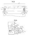
- FIG. 5 is a diagram which illustrates an image forming apparatus main body in a state where an opening and closing cover is opened in FIG. 2 .
- FIG. 6 is a front view in a state where the opening and closing cover is opened in FIG. 2 .
- FIG. 7 is a diagram which illustrates a roller hook according to a second embodiment.
- FIG. 8 is a diagram which illustrates a transfer device according to the second embodiment, and a state where the opening and closing cover is closed.
- FIG. 9 is a diagram which illustrates a state where the opening and closing cover is about to close in FIG. 8 .
- FIG. 10 is a diagram which illustrates the roller hook according to a third embodiment.
- FIG. 11 is a diagram which illustrates a transfer device according to the third embodiment, and a state where the highest nip load is adjusted.
- FIG. 12 is a diagram which illustrates the transfer device according to the third embodiment, and an adjusting state where the nip load is weaker than that in FIG. 11 .
- FIG. 13 is a diagram which illustrates the transfer device according to the third embodiment, and a state where the nip load is not applied.
- FIG. 14 is a diagram which illustrates a transfer device according to a fourth embodiment, and an adjusting state of a stop position of the transfer roller.
- FIG. 15 is a diagram which illustrates the transfer device according to the fourth embodiment, and a state where the stop position of the transfer roller is adjusted to a position different from the position in FIG. 14 .
- FIG. 16 is a diagram which illustrates a transfer device according to a fifth embodiment, and an adjusting state of a stop position of the transfer roller.
- FIG. 17 is a diagram which illustrates a transfer device according to the fifth embodiment, and a state where the stop position of the transfer roller is adjusted to a position different from the position in FIG. 16 .
- FIG. 18 is a diagram which illustrates a transfer device according to a sixth embodiment.
- a transfer device which transfers a toner image to a member for transferral which passes through a nip portion which is formed by a first transfer member disposed on a main body of an apparatus, and a second transfer member which is disposed on an opening and closing cover which opens and closes an opening portion of the main body of the apparatus.
- a positioning member which positions the second transfer member which moves according to a closing operation of the opening and closing cover, to a predetermined distance with respect to the first transfer member.
- an engaging member which engages with the second transfer member, and pushes the second transfer member toward a position which is positioned by the positioning member, by being urged by an elastic member.
- FIG. 1 is a front view which illustrates a schematic configuration of an electrophotography-type image forming apparatus.
- the image forming apparatus 1 shown in FIG. 1 is a Multi-Function Peripheral (MFP) which has an opening and closing cover 3 on one side of a main body 2 of the image forming apparatus, and an image reading unit 4 on the upper side of the main body 2 of the image forming apparatus.
- An endless transfer belt (a primary transfer member) 5 which moves in a direction of an arrow a, is disposed in the main body 2 of the image forming apparatus.
- the transfer belt 5 is turned over a roller such as a driving roller 5 a , a transfer roller 11 on one side of a transfer device 10 , or the like.
- a process cartridge 6 Y of yellow, a process cartridge 6 M of magenta, a process cartridge 6 C of cyan, and a process cartridge 6 K of black are disposed in the periphery of the transfer belt 5 .
- Photoconductive drums 7 Y, 7 M, 7 C, and 7 K of each process cartridge come into contact with the transfer belt 5 in a pressurizing manner, through the primary transfer rollers 8 Y, 8 M, 8 C, and 8 K at a primary transfer position.
- a latent image is formed in each of the photoconductive drums 7 Y, 7 M, 7 C, and 7 K, using exposure light of images from a laser unit 9 , and each latent image is developed using toner and using the developing unit of each of process cartridges 6 Y, 6 M, 6 C, and 6 K.
- the toner image which is formed on each of photoconductive drums 7 Y, 7 M, 7 C, and 7 K is primarily transferred to the transfer belt 5 , using the primary transfer rollers 8 Y, 8 M, 8 C, and 8 K, and moves toward a secondary transfer position on which a transfer device 10 is disposed.
- one transfer roller 11 and the other transfer roller 12 are disposed in the inside of the transfer roller 5 , to face each other, with the transfer belt 5 interposed therebetween.
- the other transfer roller 12 is pressurized toward the one transfer roller 11 .
- One transfer roller 11 is attached to a main body 2 side of an image forming apparatus, and the other transfer roller 12 is attached to an opening and closing cover 3 side.
- a sheet S is conveyed to a nip portion between the other transfer roller 12 and the transfer roller 5 , from a sheet feeding cassette 13 , and the toner image on the transfer belt 5 is transferred to the sheet S.
- the sheet S on which an unfixed toner image is secondarily transferred is conveyed toward a fixing unit 14 , and the unfixed toner image is fixed to the sheet S by being pressurized and heated.
- the sheet S on which the image is fixed is conveyed to a discharge tray 16 , through a sheet conveying path 15 .
- a flapper 17 moves in a direction of an arrow b, and the sheet S on which one-sided printing is ended, is guided to a reverse path 18 .
- a portion of the reverse path 18 is attached to the opening and closing cover 3 . Accordingly, when paper jamming occurs in the transfer device 10 , if the opening and closing cover 3 which clogs an opening portion 2 a of the main body 2 of the image forming apparatus, is opened, the other transfer roller 12 is separated from a secondary transfer position. Accordingly, it is possible for someone to insert their hands into the secondary transfer position, and it is possible to easily treat the jamming of the sheet S which is carrying the unfixed toner image.
- FIG. 2 is a partially-cut front view of the transfer device shown in FIG. 1 .
- FIG. 3 is a diagram which illustrates the positioning member shown in FIG. 2 .
- FIG. 4 is a diagram which illustrates the roller hook shown in FIG. 2 .
- FIG. 5 is a diagram which illustrates the main body of the image forming apparatus when the opening and closing cover shown in FIG. 2 is opened.
- FIG. 6 is a front view of the opening and closing cover shown in FIG. 2 , which is opened.
- a roller axis portion 11 b protrudes from each of both ends of the roller main body 11 a in an axial direction toward the outside in the axial direction, and these roller axis portions 11 b are rotatably and pivotally supported by the main body 2 of the image forming apparatus.
- the positioning member 30 which performs the positioning of the other transfer roller 12 is fixed to both sides of the roller main body 11 a in the axial direction, respectively in the main body 2 of the image forming apparatus. As shown in FIG.
- an engaging portion 32 which extends in a horizontal direction from a flat plate-shaped main body 31 , protrudes to the outside of the main body 2 of the apparatus, through the opening portion 2 a of the main body 2 of the apparatus.
- the engaging portion 32 has a fitting recess 33 whose front end is open.
- the fitting recess 33 is formed to be surrounded by an upper arm portion 34 and a lower arm portion 35 which vertically face each other, and extends vertically and horizontally, and a deep end surface 36 which extends in a perpendicular direction.
- Both roller axis portions 11 b of the one side transfer roller 11 are attached with, for example, an antifriction bearing 37 , and a roller hook 38 is mounted in the antifriction bearing 37 .
- a hole portion 39 which fits to an outer periphery portion of the antifriction bearing 37 is formed in the center portion.
- a hook portion 41 is formed in a front end portion of a first lever portion 40 of the roller hook 38 , and a spring hole 45 to which a pressurizing spring 44 for applying the nip load to a second lever portion 42 is attached, is formed.
- One end of the pressurizing spring 44 is attached to the main body 2 of the image forming apparatus, and the other end is attached to the spring hole 45 , and rotates the roller hook 38 clockwise when a spring force is applied in a direction of an arrow c.
- a locking end surface 43 is positioned in front of the fitting recess 33 , and an engaging space 46 for engaging is formed between the hook portion 41 and a front end of the lower arm portion 35 .
- a roller axis portion 12 b protrudes from each of both ends of the roller main body 12 a in an axial direction to the outside in the axial direction.
- an antifriction bearing 50 is mounted on each of both roller axis portions 12 b , and a front end portion of each roller axis portion 12 b is rotatably and pivotally supported by an axis hole portion 3 b which is formed on a side wall portion 3 a of the opening and closing cover 3 .
- the antifriction bearing 50 engages with the fitting recess 33 in a vertical direction without backlash.
- An internal diameter of the axis hole portion 3 b is formed to be larger than an external diameter of the roller axis portion 12 b , and the roller axis portion 12 b is able to move in the axis hole portion 3 b in a radial direction. Accordingly, the other transfer roller 12 is able to move in a plane which is perpendicular to the other transfer roller in an axial direction, with respect to the opening and closing cover 3 .
- a cover lock axis 2 b facing the opening portion 2 is attached facing the main body 2 of the image forming apparatus in a front and rear direction, to an upper position of the opening 2 a .
- a bearing member 2 c for the opening and closing cover facing the opening portion 2 a is attached facing the main body 2 of the image forming apparatus in the front and rear direction, to a lower position of the opening 2 .
- An opening and closing axis 3 c which is pivotally supported by each bearing member 2 c , is attached to the lower portion of the opening and closing cover 3 , and the opening and closing cover 3 is opened and closed using the opening and closing axis 3 c as a fulcrum.
- a hook 48 for the cover lock which is urged in a direction of an arrow d using a locking spring 47 , is provided to correspond to a cover lock axis 2 b in the opening and closing cover 3 . Further, if the opening and closing cover 3 is closed, the hook 48 for the cover lock engages with the cover lock axis 2 b , and the opening and closing cover 3 is locked at a closing position.
- the engaging space 46 for the engaging is positioned in a moving trace of the antifriction bearing 50 which is provided in the other transfer roller 12 .
- the antifriction bearing 50 rotates the roller hook 38 counterclockwise against the spring force of the pressurizing spring 44 , in order to widen the engaging space 46 . Further, if the antifriction bearing 50 is pushed into the fitting recess 33 , the roller hook 38 rotates clockwise due to the spring force of the pressurizing spring 44 , and the locking end surface 43 of the hook portion 41 pushes the antifriction bearing 50 toward the deep end surface 36 .
- the distance between axes of the one transfer roller 11 and the other transfer roller 12 is set to a predetermined distance under the optimal transfer conditions, at a position where the antifriction bearing 50 of the other transfer roller 12 comes into close contact with the deep end surface 36 of the positioning member 30 .
- the spring force of the pressurizing spring 44 is applied to the other transfer roller 12 through the roller hook 38 which is attached to the main body 2 side of the image forming apparatus. Accordingly, it is possible to pressurize the other transfer roller 12 with respect to the one transfer roller 11 , with a predetermined nip load.
- the locking end surface 43 is perpendicular to a horizontal axis line L which connects center axes of both transfer rollers 11 and 12 , in a state which is shown in FIG. 2 , where the roller hook 38 locks the antifriction bearing 50 of the other transfer roller 12 , and the predetermined distance between axes which is determined under the optimal transfer conditions, is set with respect to the one transfer roller 11 .
- the center axis of the other transfer roller 12 and the center of the opening and closing axis 3 c are deviated by a distance L 1 .
- the spring force of the pressurizing spring 44 which is applied to the other transfer roller 12 is not applied to the opening and closing cover 3 . Therefore, the strength or the like, of the opening and closing cover 3 may be set without considering the nip load which is applied to the one transfer roller 11 by the other transfer roller 12 .
- the spring force of the pressurizing spring 44 is applied to the one transfer roller 11 using the roller hook 38 , in a state where the roller hook 38 is disposed between the positioning member 30 and the roller main body 11 a , and both roller axis portions 12 b of the other transfer roller 12 are supported by the positioning member 30 .
- the other transfer roller 12 is bent toward the one transfer roller 11 , using both the positioning members 30 as a fulcrum. For this reason, it is possible for the roller main body 12 a of the other transfer roller 12 to apply a substantially uniform nip load along the axial direction to the roller main body 11 a of the one transfer roller 11 .
- the roller hook 30 rotates counterclockwise, the locking end surface 43 is retreated from the front of the fitting recess 33 of the positioning member 30 to widen the locking space 46 , and the locking of the antifriction bearing 50 of the other transfer roller 12 is released.
- FIG. 7 illustrates a roller hook according to a second embodiment
- FIG. 8 illustrates a transfer device where an opening and closing cover is closed, according to the second embodiment of the invention.
- FIG. 9 is a diagram which illustrates a state where the opening and closing cover is about to be closed in FIG. 8 .
- a locking end surface 63 of a hook portion 41 is formed to be an inclined surface with an angle ⁇ , and a length of a second lever portion 42 which is sufficient to come into contact with a stopper axis 65 , is provided to a front end side of a spring hole 45 .
- the locking end surface 63 is formed to be an inclined surface with the angle ⁇ , with respect to a horizontal axis line L which connects the center axes of both transfer rollers 11 and 12 .
- the antifriction bearing 50 which is provided in the other transfer roller 12 comes into contact with the locking end surface 63 immediately before an opening and closing cover 3 is completely closed.
- the roller hook 60 rotates clockwise due to a spring force of a pressurizing spring 44 , the antifriction bearing 50 is pushed toward the deep end surface 36 of the fitting recess 33 using a wedge effect of the locking end surface 63 , and the roller hook 60 stops rotating at a stop position where a second lever portion 42 which is a stopper shown in FIG. 8 , comes into close contact with a stopper axis 65 .
- the one transfer roller 11 and the other transfer roller 12 are maintained at a predetermined distance between axes which is determined under the optimal transfer conditions, similarly to the first embodiment, and a predetermined nip load is generated.
- the force of the roller hook 60 which pulls the other transfer roller 12 to the one transfer roller 11 is generated due to the wedge effect of the locking end surface 63 , using a spring force of the pressurizing spring 44 .
- a return force of the pressurizing spring 44 is added to the opening and closing cover 3 , accordingly, it is possible to smoothly close the opening and closing cover 3 , and the opening and closing cover 3 is elastically maintained at a closing position, using the spring force of the pressurizing spring 44 .
- FIG. 10 illustrates a roller hook according to a third embodiment.
- the third embodiment has a structure in which a distance between axes of the one transfer roller 11 and the other transfer roller 12 is changed, and the nip load is adjusted, in a state where an opening and closing cover 3 is closed.
- the distance between axes of the pair of transfer rollers 11 and 12 is short.
- the distance between axes of the pair of transfer rollers 11 and 12 is medium.
- FIG. 13 the distance between axes of the pair of transfer rollers 11 and 12 is widened to be a non-contact state.
- the eccentric cam 72 has a configuration in which a cam plate 74 is fixed to a cam axis 73 , by deviating an axis center of the cam axis 73 which is rotatably and pivotally supported by the main body 2 of the image forming apparatus and an axis center of the disc-shaped cam plate 74 , and a second lever portion 42 comes into contact with the outer peripheral surface of the cam plate 74 . If an offset amount at a cam position shown in FIG. 11 is 0, the offset amount in the eccentric cam 72 increases as the cam axis 73 rotates clockwise.
- FIG. 12 shows a case where the rotation angle of the cam axis 73 is 90 degrees
- FIG. 13 shows a case where the rotation angle of the cam axis 73 is 180 degrees.
- the offset amount of the eccentric cam 72 shown in FIG. 13 is the maximum.
- the eccentric cams 72 which are respectively provided to both ends of the one transfer roller 11 in an axial direction, may rotatably drive the cam axis 73 , individually, for example, using a motor 75 .
- the antifriction bearing 50 which is provided to the other transfer roller 12 is set to a distance between axes which is determined under the optimal transfer conditions in which the antifriction bearing 50 comes into close contact with the deep end surface 63 of the fitting recess 33 of the positioning member 30 .
- a force is not applied in a direction of push back.
- the counterclockwise rotation of the roller hook 70 is suppressed using the eccentric cam 72 as the stopper, the pair of transfer rollers 11 and 12 are set to the distance between axes which is determined under the optimal transfer conditions, and the optimal nip load is applied.
- the nip load between the transfer rollers in the front and rear direction becomes uneven, when the distance between axes of the other transfer roller 12 in the front and rear direction is different, due to a variation in precision of a size of the positioning member 30 which is provided on the main body 2 side of the image forming apparatus, or a precision of attachment. There is a problem that the uneven nip load between the transfer rollers causes deterioration of images.
- the roller hook 70 when opening the opening and closing cover 3 , the roller hook 70 largely rotates counterclockwise, so as to widen a space 46 in advance. If the opening and closing cover 3 rotates in an opening direction in this state, the antifriction bearing 50 allows the roller hook 70 to slightly rotate counterclockwise, to further widen the space 46 . For this reason, the antifriction bearing 50 is extracted from the space 46 , thereby opening the opening and closing cover 3 .
- the nip load is set to the optimal transfer conditions, by rotating the eccentric cams 72 which are disposed at the front and rear of the one transfer roller 11 , respectively, to a position which is shown in FIG. 11 , due to a driving by a motor M, or a position shown in FIG. 12 where the distance between axes in the front and rear is separately adjusted. For this reason, a reaction force of the nip load is not applied to the opening and closing cover 3 , when closing the opening and closing cover 3 .
- FIGS. 14 and 15 illustrate a transfer device according to a fourth embodiment.
- a modified example of the second embodiment shown in FIGS. 7 to 9 is illustrated, and in the embodiment, a stop position of a roller hook 60 can be adjusted.
- FIGS. 16 and 17 illustrate a transfer device according to a fifth embodiment.
- a modified example of the second embodiment shown in FIGS. 7 to 9 is illustrated, similarly to the fourth embodiment. Further, it is possible to adjust a stop position of a roller hook 60 .
- the eccentric cam 72 is rotated from a position shown in FIG. 16 where the offset amount is 0, by driving a cam axis 73 using a motor, the offset amount increases, and a position where a second lever portion 42 of the roller hook 60 comes into close contact with a cam plate 74 is changed.
- FIG. 18 illustrates a sixth embodiment.
- a roller hook 38 in contrast to the first embodiment shown in FIG. 2 , a roller hook 38 , a positioning member 30 , and a pressurizing spring 44 are disposed on an opening and closing cover 3 .
- an antifriction bearing 37 which is provided in the one transfer roller 11 which is disposed on a main body 2 side of the image forming apparatus, is fitted to a fitting recess 33 of a positioning member 30 .
- the roller hook 38 engages with the antifriction bearing 37 , and draws in the antifriction bearing 37 towards the other transfer roller 12 to have the predetermined distance of axes.
- a roller axis 11 b of the one transfer roller 11 is shaft supported by a shaft hole 2 d which is provided on the main body 2 side of the image forming apparatus.
- the inner diameter of the shaft hole 2 d is larger than the outer diameter of the roller axis 11 b , and the one transfer roller 11 can move freely around the shaft.
- the positioning member 30 and the roller hook 38 are disposed on the opening and closing cover 3 side; however, this reverse configuration may be similarly applied to the above-described second embodiment to the fifth embodiment.
- the opening and closing cover 3 rotated around the opening and closing axis 3 as the fulcrum; however, the cover may be a translation-type opening and closing cover.
Landscapes
- Physics & Mathematics (AREA)
- General Physics & Mathematics (AREA)
- Electrostatic Charge, Transfer And Separation In Electrography (AREA)
- Electrophotography Configuration And Component (AREA)
Abstract
Description
Claims (11)
Priority Applications (1)
| Application Number | Priority Date | Filing Date | Title |
|---|---|---|---|
| US13/247,935 US8849158B2 (en) | 2010-10-21 | 2011-09-28 | Transfer device of image forming apparatus and related image forming apparatus |
Applications Claiming Priority (5)
| Application Number | Priority Date | Filing Date | Title |
|---|---|---|---|
| US40547710P | 2010-10-21 | 2010-10-21 | |
| US40548410P | 2010-10-21 | 2010-10-21 | |
| US40550010P | 2010-10-21 | 2010-10-21 | |
| US40550810P | 2010-10-21 | 2010-10-21 | |
| US13/247,935 US8849158B2 (en) | 2010-10-21 | 2011-09-28 | Transfer device of image forming apparatus and related image forming apparatus |
Publications (2)
| Publication Number | Publication Date |
|---|---|
| US20120099896A1 US20120099896A1 (en) | 2012-04-26 |
| US8849158B2 true US8849158B2 (en) | 2014-09-30 |
Family
ID=45973132
Family Applications (1)
| Application Number | Title | Priority Date | Filing Date |
|---|---|---|---|
| US13/247,935 Expired - Fee Related US8849158B2 (en) | 2010-10-21 | 2011-09-28 | Transfer device of image forming apparatus and related image forming apparatus |
Country Status (2)
| Country | Link |
|---|---|
| US (1) | US8849158B2 (en) |
| CN (1) | CN102455639A (en) |
Cited By (2)
| Publication number | Priority date | Publication date | Assignee | Title |
|---|---|---|---|---|
| US20180059607A1 (en) * | 2016-08-30 | 2018-03-01 | Canon Kabushiki Kaisha | Bearing device and transferring device |
| US10046931B2 (en) * | 2016-06-10 | 2018-08-14 | Canon Kabushiki Kaisha | Sheet conveying apparatus, image forming apparatus, and image reading apparatus |
Families Citing this family (14)
| Publication number | Priority date | Publication date | Assignee | Title |
|---|---|---|---|---|
| EP2587314B1 (en) | 2011-10-26 | 2020-09-23 | Hewlett-Packard Development Company, L.P. | Image forming apparatus |
| JP5972031B2 (en) * | 2012-04-27 | 2016-08-17 | キヤノン株式会社 | Image forming apparatus |
| US9031461B2 (en) * | 2013-03-15 | 2015-05-12 | Lexmark International, Inc. | Transfer roll assembly for an electrophotographic image forming device |
| US9291954B1 (en) * | 2015-02-17 | 2016-03-22 | Kabushiki Kaisha Toshiba | Image forming apparatus |
| JP6641736B2 (en) * | 2015-06-22 | 2020-02-05 | 富士ゼロックス株式会社 | Image forming device |
| JP6659146B2 (en) * | 2016-01-19 | 2020-03-04 | キヤノン株式会社 | Image forming device |
| JP6658096B2 (en) * | 2016-02-29 | 2020-03-04 | ブラザー工業株式会社 | Image forming device |
| JP6508143B2 (en) * | 2016-08-08 | 2019-05-08 | 京セラドキュメントソリューションズ株式会社 | Transfer unit and image forming apparatus |
| JP6579060B2 (en) * | 2016-08-24 | 2019-09-25 | 京セラドキュメントソリューションズ株式会社 | Image forming apparatus |
| JP6772693B2 (en) * | 2016-09-12 | 2020-10-21 | 富士ゼロックス株式会社 | Opening / closing door positioning mechanism and image forming device using this |
| JP7024245B2 (en) * | 2017-08-10 | 2022-02-24 | ブラザー工業株式会社 | Image forming device |
| US10732547B1 (en) * | 2019-03-20 | 2020-08-04 | Fuji Xerox Co., Ltd. | Image forming apparatus |
| JP7414581B2 (en) * | 2020-02-26 | 2024-01-16 | キヤノン株式会社 | Image forming device |
| JP7443956B2 (en) | 2020-06-26 | 2024-03-06 | 京セラドキュメントソリューションズ株式会社 | Opening/closing door mechanism |
Citations (10)
| Publication number | Priority date | Publication date | Assignee | Title |
|---|---|---|---|---|
| US5787326A (en) * | 1995-04-03 | 1998-07-28 | Matsushita Electric Industrial Co., Ltd. | Image forming apparatus having a cover for protecting a transfer region of an intermediate transfer member when a door is opened |
| JP2004020574A (en) | 2002-06-12 | 2004-01-22 | Panasonic Communications Co Ltd | Color recording device |
| US20070110486A1 (en) * | 2005-11-02 | 2007-05-17 | Hiroyuki Okaji | Image forming apparatus capable of stably conveying recording medium |
| US20090022514A1 (en) * | 2007-07-17 | 2009-01-22 | Ricoh Company, Limited | Image forming apparatus |
| US20090154957A1 (en) * | 2007-12-14 | 2009-06-18 | Canon Kabushiki Kaisha | Image forming apparatus |
| JP2009251135A (en) | 2008-04-03 | 2009-10-29 | Canon Inc | Image forming apparatus |
| US20100003051A1 (en) * | 2008-07-04 | 2010-01-07 | Sekine Takuya | Transfer unit and image forming apparatus |
| US20100247173A1 (en) * | 2009-03-26 | 2010-09-30 | Brother Kogyo Kabushiki Kaisha | Image Forming Apparatus |
| US20100278557A1 (en) * | 2009-05-01 | 2010-11-04 | Fuji Xerox Co., Ltd. | Image forming apparatus |
| US20110236059A1 (en) * | 2010-03-26 | 2011-09-29 | Fuji Xerox Co., Ltd. | Image forming apparatus |
-
2011
- 2011-09-28 US US13/247,935 patent/US8849158B2/en not_active Expired - Fee Related
- 2011-10-20 CN CN2011103217435A patent/CN102455639A/en active Pending
Patent Citations (10)
| Publication number | Priority date | Publication date | Assignee | Title |
|---|---|---|---|---|
| US5787326A (en) * | 1995-04-03 | 1998-07-28 | Matsushita Electric Industrial Co., Ltd. | Image forming apparatus having a cover for protecting a transfer region of an intermediate transfer member when a door is opened |
| JP2004020574A (en) | 2002-06-12 | 2004-01-22 | Panasonic Communications Co Ltd | Color recording device |
| US20070110486A1 (en) * | 2005-11-02 | 2007-05-17 | Hiroyuki Okaji | Image forming apparatus capable of stably conveying recording medium |
| US20090022514A1 (en) * | 2007-07-17 | 2009-01-22 | Ricoh Company, Limited | Image forming apparatus |
| US20090154957A1 (en) * | 2007-12-14 | 2009-06-18 | Canon Kabushiki Kaisha | Image forming apparatus |
| JP2009251135A (en) | 2008-04-03 | 2009-10-29 | Canon Inc | Image forming apparatus |
| US20100003051A1 (en) * | 2008-07-04 | 2010-01-07 | Sekine Takuya | Transfer unit and image forming apparatus |
| US20100247173A1 (en) * | 2009-03-26 | 2010-09-30 | Brother Kogyo Kabushiki Kaisha | Image Forming Apparatus |
| US20100278557A1 (en) * | 2009-05-01 | 2010-11-04 | Fuji Xerox Co., Ltd. | Image forming apparatus |
| US20110236059A1 (en) * | 2010-03-26 | 2011-09-29 | Fuji Xerox Co., Ltd. | Image forming apparatus |
Cited By (3)
| Publication number | Priority date | Publication date | Assignee | Title |
|---|---|---|---|---|
| US10046931B2 (en) * | 2016-06-10 | 2018-08-14 | Canon Kabushiki Kaisha | Sheet conveying apparatus, image forming apparatus, and image reading apparatus |
| US20180059607A1 (en) * | 2016-08-30 | 2018-03-01 | Canon Kabushiki Kaisha | Bearing device and transferring device |
| US10203649B2 (en) * | 2016-08-30 | 2019-02-12 | Canon Kabushiki Kaisha | Bearing device and transferring device |
Also Published As
| Publication number | Publication date |
|---|---|
| CN102455639A (en) | 2012-05-16 |
| US20120099896A1 (en) | 2012-04-26 |
Similar Documents
| Publication | Publication Date | Title |
|---|---|---|
| US8849158B2 (en) | Transfer device of image forming apparatus and related image forming apparatus | |
| US8340563B2 (en) | Sheet conveying apparatus and image forming apparatus | |
| JP5483990B2 (en) | Sheet conveying apparatus and image forming apparatus | |
| JP5920028B2 (en) | Image forming apparatus | |
| US8169460B2 (en) | Image forming apparatus | |
| JP2009139448A (en) | Image forming apparatus | |
| US10179713B2 (en) | Sheet feeding device, feeding tray, and image forming apparatus | |
| US9718633B2 (en) | Sheet conveyance apparatus and image forming apparatus | |
| JP2013228655A (en) | Sheet conveyance device and image forming apparatus | |
| US9354595B2 (en) | Toner container and image forming apparatus including the toner container | |
| US9494918B2 (en) | Image forming apparatus | |
| JP2010015059A (en) | Transfer unit and image forming apparatus | |
| US9568871B2 (en) | Duplex image forming apparatus with two-side conveyance unit rotatable between open and closed positions | |
| US10046931B2 (en) | Sheet conveying apparatus, image forming apparatus, and image reading apparatus | |
| US10481551B2 (en) | Image forming apparatus with pivotable transfer unit positioning portion | |
| US9977375B2 (en) | Image forming device | |
| JP2010197814A (en) | Positioning mechanism for transfer roller and image forming apparatus provided with the same | |
| US20130193639A1 (en) | Skewed sheet correcting device and image forming apparatus | |
| US12049375B2 (en) | Sheet feeding apparatus and image forming apparatus | |
| US8660462B2 (en) | Image forming apparatus with replaceable member | |
| JP2002182445A (en) | Transfer material carrying mechanism and image forming device | |
| US10768548B2 (en) | Image forming apparatus | |
| CN107703725B (en) | Transfer unit and image forming apparatus | |
| JP5968106B2 (en) | Sheet conveying apparatus and image forming apparatus | |
| JP6579060B2 (en) | Image forming apparatus |
Legal Events
| Date | Code | Title | Description |
|---|---|---|---|
| AS | Assignment |
Owner name: KABUSHIKI KAISHA TOSHIBA, JAPAN Free format text: ASSIGNMENT OF ASSIGNORS INTEREST;ASSIGNOR:KAMANO, TADAO;REEL/FRAME:026986/0256 Effective date: 20110916 Owner name: TOSHIBA TEC KABUSHIKI KAISHA, JAPAN Free format text: ASSIGNMENT OF ASSIGNORS INTEREST;ASSIGNOR:KAMANO, TADAO;REEL/FRAME:026986/0256 Effective date: 20110916 |
|
| STCF | Information on status: patent grant |
Free format text: PATENTED CASE |
|
| CC | Certificate of correction | ||
| MAFP | Maintenance fee payment |
Free format text: PAYMENT OF MAINTENANCE FEE, 4TH YEAR, LARGE ENTITY (ORIGINAL EVENT CODE: M1551) Year of fee payment: 4 |
|
| FEPP | Fee payment procedure |
Free format text: MAINTENANCE FEE REMINDER MAILED (ORIGINAL EVENT CODE: REM.); ENTITY STATUS OF PATENT OWNER: LARGE ENTITY |
|
| LAPS | Lapse for failure to pay maintenance fees |
Free format text: PATENT EXPIRED FOR FAILURE TO PAY MAINTENANCE FEES (ORIGINAL EVENT CODE: EXP.); ENTITY STATUS OF PATENT OWNER: LARGE ENTITY |
|
| STCH | Information on status: patent discontinuation |
Free format text: PATENT EXPIRED DUE TO NONPAYMENT OF MAINTENANCE FEES UNDER 37 CFR 1.362 |
|
| FP | Lapsed due to failure to pay maintenance fee |
Effective date: 20220930 |