US884792A - Railroad-switch. - Google Patents
Railroad-switch. Download PDFInfo
- Publication number
- US884792A US884792A US38708207A US1907387082A US884792A US 884792 A US884792 A US 884792A US 38708207 A US38708207 A US 38708207A US 1907387082 A US1907387082 A US 1907387082A US 884792 A US884792 A US 884792A
- Authority
- US
- United States
- Prior art keywords
- switch
- block
- shaft
- rod
- car
- Prior art date
- Legal status (The legal status is an assumption and is not a legal conclusion. Google has not performed a legal analysis and makes no representation as to the accuracy of the status listed.)
- Expired - Lifetime
Links
- 210000003414 extremity Anatomy 0.000 description 4
- 230000000630 rising effect Effects 0.000 description 3
- 210000001364 upper extremity Anatomy 0.000 description 3
- 208000004067 Flatfoot Diseases 0.000 description 2
- 238000010276 construction Methods 0.000 description 1
- 230000000881 depressing effect Effects 0.000 description 1
- 230000000994 depressogenic effect Effects 0.000 description 1
- 239000000428 dust Substances 0.000 description 1
- 210000003746 feather Anatomy 0.000 description 1
- 230000001788 irregular Effects 0.000 description 1
- 239000002184 metal Substances 0.000 description 1
- 230000008520 organization Effects 0.000 description 1
- 238000009877 rendering Methods 0.000 description 1
Images

Classifications
-
- B—PERFORMING OPERATIONS; TRANSPORTING
- B61—RAILWAYS
- B61L—GUIDING RAILWAY TRAFFIC; ENSURING THE SAFETY OF RAILWAY TRAFFIC
- B61L11/00—Operation of points from the vehicle or by the passage of the vehicle
- B61L11/02—Operation of points from the vehicle or by the passage of the vehicle using mechanical interaction between vehicle and track
Definitions
- This invention relates to switch operating mechanism for cars, and pertains particularly to that type of track switch throwing mechanism whereby a motorman can actuate the switch from his station at the controlling apparatus for the car, thus rendering it unnecessary for him to dismount and throw the switch when desired to turn from the main line or track into a branch line, cross over, turn out, or the like.
- the mechanism embodying the features of the invention and conjointly contributing to a successful switching operation is carried in part by the car and partially disposed between the track rails on which the car has movement, the track rails includinga switch rail or tongue with which a portion of the mechanism is operatively connected.
- the invention consists in the construction and arrangement of parts which will be more fully hereinafter specified in preferred form.
- the primary object of the invention is to simplify switch operating mechanism of this class and to positively dispose the switch throwing elements carried by the car eitherinto operative or inoperative positions and prevent a motorman from carelessly or insufficiently actuating the switch throwing mechanism under his control on the car.
- a further object of the invention is to insure a positive disposition of switch throwing mechanism carried by a car and under the control of the motorman with relation to switch operating means located in a track bed and over which the car is adapted to move.
- the switch operating means directly coacting with the switch rail will be hereinafter described as being located centrally with respect to the main track rails, and the switch throwing devices carried by the car will also be specified as being centrally located on the platform of the car, but this exact disposition of the entire mechanism is not essential, it being possible to arrange the switch operating means at one side of the trackrail and correspondingly situate the throwing mechanism on the view of a portion of a railway track system showing a switch rail and means for actuating the latter.
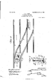
- Fig. 2 is a side elevation of a portion of the track system shown by Fig. 1 and a part of a car embodying. the features of the invention.
- Fig. 3 is an enlarged section on the line 33, Fig.
- Fig. 4 is an enlarged section on the line 4-4, Fig. 1.
- Fig. 5 is a top plan View of a portion of the platform of the car showing the improved switch throwing mechanism carried thereby partially in section.
- Fig. 6 is a longitudinal sectional view of a portion of the platform of the car showing the switch throwing mechanism applied thereto and represented in two positions in full and dotted lines, the bearing hanger for a part of the switch throwing mechanism being shown in section.
- Fig. 7 is a diagrammatic view showing in elevation the switch throwing mechanism carried by the car and the switch rail or tongue actuating mechanism, in operative relation.
- the numeral 1 designates a main track, and 2 a supplementary track connected to the main track by rails 3 in the ordinary manner.
- the supplementary track 2 may be either a siding or a component of a double track system.
- a part of the rails 3 coijperates with a frog 4, in which is mounted a switch tongue 5.
- Projecting from the frog 4 is a base plate 6, having a bearing 7 rising therefrom and suitably apertured to movably receive one extremity of the transversely extending rod 8, the opposite extremity of the said rod having sliding movement in a flange 9 of the plate 6, the said flange being located adjacent to the switch tongue 5.
- Terminally secured to the frog 4, and the upper end of the bearing 7, is a transversely extending cover plate 10, having a longitudinal slot 11 formed therein.
- the rod 8 is located directly beneath the slot 11, and thereon are set collars or stop devices 12,
- a block 13 is loosely slidable on the rod 8 between the collars or stop devices 12, the said rod centrally engaging the block, and
- the plate 6 has a pair of u standing ribs 15 extending longitudinally t iereover and spaced a suitable distance, and the block 13 has grooves 16 in its lower side to engage the said ribs.
- the block 13 is freely slida'ble on the ribs, and by employing the said ribs friction on the block is greatly reduced.
- a dust-guard or plate 19 Connected to the post or stud 17 below the roller 18, and movable therewith, is a dust-guard or plate 19, which is of such dimensions as to always extend over the slot 11, irrespective of the movement thereof.
- the rod 8 is connected at one end to the switch tongue 5, .and as the block 13 is moved in opposite directions over the rod 8, it acts through the springs 14 to correspondingly throw the switch tongue.
- the block 13 does not have any tendency to bend the rod 8 when actuated, in view of the fact that the said rod projects centrally through the block, and the atter is loose on the rod. Furthermore, the block 13 is prevented from having irregular movement by the ribs 15, and hence wear on the cooperating parts is prevented and the durability thereof increased.
- the switch throwing mechanism is carried by the platform 20 of the car close .to the dash-board 21, and consists of a vertically movable, freely rotatable shaft or staff 22, having fixed to the lower end thereof a flat foot 23, which always stands at an angle with respect to the said shaft.
- the foot 23 is preferably a flat plate of suitable hard metal, and the opposite faces thereof are adapted to contact with diametrically opposite portions of the antifrictional roller 18.
- Theshaft or staff 22 moves through a hanger 24 depending from the underside of the platform 20 of the car, and secured on the said shaft or staff is a collar 25, which serves to engage one extremity of a depressing spring 26, surrounding the shaft between the collar 25 and the bottom of the platform 20 of the car.
- the shaft or staff 22 has vertical sliding movement and rotation in a locking plate 27,
- a head 29 is secured on the upper end of the shaft or staff 22, the said upper end of the shaft being squared or formed angular in cross section, and the head having a correspondingly shaped bore or opening therethrough to receive the shaft 8.
- the upper extremity of the shaft has free vertical movement through the head, and the latter may be readily rotated on the sleeve or collar 28, and when rotated it is obvious that the shaft or staff will be turned in a like direction.
- a handle or grip 30 is provided and formed with a yoked extremity 31, which is pivoted to the head 29 and has links 32 movably'attached to opposite portions thereof and to the shaft or staff below the sleeve or collar 28.
- the shaft or staff 22 When the grip or handle 30 is thrown inwardly, the shaft or staff 22 will be free for depression by the spring 26, and when the handle or grip is thrown outwardly in reverse directions and over the center of the upper extremity of the shaft or staff, and forwardly beyond the said 5 center, the shaft or staff will be elevated against the resistance of the spring 26 and become locked against accidental depression, in view of the position of the handle or grip a forward direction, and the tension of the said spring 26, which then acts to hold the handle or grip in close engagement with the upper edge of the dash-board 21.
- the shaft or staff 22 works in an opening 32 in the plate 27, and radiating from said 5 opening and communicating therewith are two slots 33 and 34, to receive a splineor feather 35 projecting rearwardly from the shaft or staff and operating to prevent the latter from rotating, and thereby hold the foot 23 in either one of two adjusted positions.
- the locking plate 27 has abutments or stops 36 rising therefrom adjacent to the outer walls of the said slots 33 .and 341, and between the said slots is a boss 37, which serves as a guard and has -0 posite inclined faces terminating coincident y with the inner walls of the slots to cause the spline35 to positively pass downwardly into either one or the other of said slots when the shaft or staff is released for depression, and without requiring precise attention or accurate manipulation on the part of the motorman.
- the shaft or staff 22 is turned so as to bring the foot 23 into an opposite angular position or to first engage the left hand portion of the roller 18, which will result in closing the switch tongue by moving the block 13 over towards the right.- hen the shaft or staff 22 is adjusted to cause the foot 23 to engage the roller 18 on the right, the spline 35 is seated in the slot 34, and when said spline is caused to engage the slot 33 the opposite portion of the roller will be engaged by the foot 23.
- switch operating mechanism in connection with surface tracks, it may also be applied to underground electric systems for throwing the switches of the latter, and in this particular application it will be only necessary to locate the mechanism as shown directly cooperating with the switch tongue below the surface of a track bed or in a conduit and connect up the same to underground switch means.
- the combination with switch devices including a switch tongue and means for moving the same, of a car having a vertically movable shaft with a lower foot and an intermediate spline, a locking plate engaged by the shaft and having spaced slots therein to receive the spline, and a grip device movably connected to the upper end of the shaft.
- the combination with switch devices including a switch tongue and means for moving the same, of a car having a vertically movable and rotatable shaft with a lower flat foot member and an intermediate spline, a locking plate on the car through which the shaft extends, the locking plate having spaced slots and abutments adjacent the outer walls of the slots, a guard with opposite inclined faces being disposed between the slots, and a grip device movably disposed on the upper eX- tremity of the shaft.
- the combination with switch devices including a switch tongue and means for moving the same, of a car having a vertically movable and rotatable shaft with a lower foot and an intermediate spline, a locking plate through which the shaft extends and having spaced slots therein to receive the said spline, a spring means on the shaft tending to depress the latter when released, and a handle or grip device movably connected to the upper end of the shaft for raising and lowering the said shaft and serving, when thrown over the upper end of the shaft in one direction, to prevent the shaft from accidentally lowering or being thrown downwardly by the spring means.
Landscapes
- Engineering & Computer Science (AREA)
- Mechanical Engineering (AREA)
- Train Traffic Observation, Control, And Security (AREA)
Description
No. 884,792. PATBNTED'APR, 14, 1908. T. J. BURKE. RAILROAD SWITCH.
APPLICATION FILED AUG. 5 1907.
2 SHEETS-SHEET 1.
WlizeaeS/ mar/zed JZBar/Z'e .PATENTED APR. 14, 1908.
-T. J. BURKE. RAILROAD SWITCH. APPLIOA TIQH. FILED AUG. 5, 1907.
2 SHEETS-SHEET 2.
I 12206 22 01 -Wazrraw c/ijBur/fe THOMAS J. BURKE, OF NEW ORLEANS, LOUISIANA.
RAILROAD-SWITCH.
Specification of Letters Patent.
Patented April 14, 1908.
Application filed August 5, 1907. Serial No. 387,082.
To all whom it may concern:
Be it known that I, THOMAS J. BURKE, a citizen of the United States, residing at New Orleans, in the parish of Orleans and State of Louisiana, have invented new and useful Improvements in Railroad-Switches, of which the following is a specification.
This invention relates to switch operating mechanism for cars, and pertains particularly to that type of track switch throwing mechanism whereby a motorman can actuate the switch from his station at the controlling apparatus for the car, thus rendering it unnecessary for him to dismount and throw the switch when desired to turn from the main line or track into a branch line, cross over, turn out, or the like.
The mechanism embodying the features of the invention and conjointly contributing to a successful switching operation is carried in part by the car and partially disposed between the track rails on which the car has movement, the track rails includinga switch rail or tongue with which a portion of the mechanism is operatively connected.
The invention consists in the construction and arrangement of parts which will be more fully hereinafter specified in preferred form.
The primary object of the invention is to simplify switch operating mechanism of this class and to positively dispose the switch throwing elements carried by the car eitherinto operative or inoperative positions and prevent a motorman from carelessly or insufficiently actuating the switch throwing mechanism under his control on the car.
A further object of the invention is to insure a positive disposition of switch throwing mechanism carried by a car and under the control of the motorman with relation to switch operating means located in a track bed and over which the car is adapted to move.
For the purpose of demonstrating a practical embodiment of the invention, the switch operating means directly coacting with the switch rail will be hereinafter described as being located centrally with respect to the main track rails, and the switch throwing devices carried by the car will also be specified as being centrally located on the platform of the car, but this exact disposition of the entire mechanism is not essential, it being possible to arrange the switch operating means at one side of the trackrail and correspondingly situate the throwing mechanism on the view of a portion of a railway track system showing a switch rail and means for actuating the latter. Fig. 2 is a side elevation of a portion of the track system shown by Fig. 1 and a part of a car embodying. the features of the invention. Fig. 3 is an enlarged section on the line 33, Fig. 1. Fig. 4 is an enlarged section on the line 4-4, Fig. 1. Fig. 5 is a top plan View of a portion of the platform of the car showing the improved switch throwing mechanism carried thereby partially in section. Fig. 6 is a longitudinal sectional view of a portion of the platform of the car showing the switch throwing mechanism applied thereto and represented in two positions in full and dotted lines, the bearing hanger for a part of the switch throwing mechanism being shown in section. Fig. 7 is a diagrammatic view showing in elevation the switch throwing mechanism carried by the car and the switch rail or tongue actuating mechanism, in operative relation.
Similar characters of reference are. employed to indicate corresponding parts in the views.
The numeral 1 designates a main track, and 2 a supplementary track connected to the main track by rails 3 in the ordinary manner. The supplementary track 2 may be either a siding or a component of a double track system. A part of the rails 3 coijperates with a frog 4, in which is mounted a switch tongue 5. Projecting from the frog 4 is a base plate 6, having a bearing 7 rising therefrom and suitably apertured to movably receive one extremity of the transversely extending rod 8, the opposite extremity of the said rod having sliding movement in a flange 9 of the plate 6, the said flange being located adjacent to the switch tongue 5. Terminally secured to the frog 4, and the upper end of the bearing 7, is a transversely extending cover plate 10, having a longitudinal slot 11 formed therein. The rod 8 is located directly beneath the slot 11, and thereon are set collars or stop devices 12,
- located between the bearing 7 and flange 9.
A block 13 is loosely slidable on the rod 8 between the collars or stop devices 12, the said rod centrally engaging the block, and
between the opposite ends of the block and the collars or stop devices 12, springs 14 are mounted on therod 8, and operate to return the block to normal position between the said collars or stop devices and also to cushion said block and the rod 8. The plate 6 has a pair of u standing ribs 15 extending longitudinally t iereover and spaced a suitable distance, and the block 13 has grooves 16 in its lower side to engage the said ribs. The block 13 is freely slida'ble on the ribs, and by employing the said ribs friction on the block is greatly reduced. Rising from the block 13 and movably extending through the slot 11 in the cover plate 10, is a post or stud 17, having an antifrictional roller 18 mounted on the upper extremity thereof above the said cover plate. Connected to the post or stud 17 below the roller 18, and movable therewith, is a dust-guard or plate 19, which is of such dimensions as to always extend over the slot 11, irrespective of the movement thereof. The rod 8 is connected at one end to the switch tongue 5, .and as the block 13 is moved in opposite directions over the rod 8, it acts through the springs 14 to correspondingly throw the switch tongue. It will be noted that the block 13 does not have any tendency to bend the rod 8 when actuated, in view of the fact that the said rod projects centrally through the block, and the atter is loose on the rod. Furthermore, the block 13 is prevented from having irregular movement by the ribs 15, and hence wear on the cooperating parts is prevented and the durability thereof increased.
The switch throwing mechanism is carried by the platform 20 of the car close .to the dash-board 21, and consists of a vertically movable, freely rotatable shaft or staff 22, having fixed to the lower end thereof a flat foot 23, which always stands at an angle with respect to the said shaft. The foot 23 is preferably a flat plate of suitable hard metal, and the opposite faces thereof are adapted to contact with diametrically opposite portions of the antifrictional roller 18. Theshaft or staff 22 moves through a hanger 24 depending from the underside of the platform 20 of the car, and secured on the said shaft or staff is a collar 25, which serves to engage one extremity of a depressing spring 26, surrounding the shaft between the collar 25 and the bottom of the platform 20 of the car. When the shaft or staff 22 is released, the spring immediately forces the same downwardly to bring the foot 23 in operative relation to the roller 18 on the post or stud 17 of the block 13, andv the collar 25 will contact with the bottom of the hanger 24 and prevent the foot 23 from being depressed too great a distance or below a predetermined plane of depress1on.
The shaft or staff 22 has vertical sliding movement and rotation in a locking plate 27,
. secured on the upper portion of the platform 20, and also engages a fixed guide sleeve or collar 28 secured to and projecting rear- Wardly from the dash-board 21, and'in alinement with the locking plate 27. On the upper end of the shaft or staff 22, a head 29 is secured, the said upper end of the shaft being squared or formed angular in cross section, and the head having a correspondingly shaped bore or opening therethrough to receive the shaft 8. The upper extremity of the shaft has free vertical movement through the head, and the latter may be readily rotated on the sleeve or collar 28, and when rotated it is obvious that the shaft or staff will be turned in a like direction. A handle or grip 30 is provided and formed with a yoked extremity 31, which is pivoted to the head 29 and has links 32 movably'attached to opposite portions thereof and to the shaft or staff below the sleeve or collar 28. By throwing the said grip or handle 30 in opposite directions over the upper end of the shaft or staff, the latter will be elevated and released for depression by the spring 26. When the grip or handle 30 is thrown inwardly, the shaft or staff 22 will be free for depression by the spring 26, and when the handle or grip is thrown outwardly in reverse directions and over the center of the upper extremity of the shaft or staff, and forwardly beyond the said 5 center, the shaft or staff will be elevated against the resistance of the spring 26 and become locked against accidental depression, in view of the position of the handle or grip a forward direction, and the tension of the said spring 26, which then acts to hold the handle or grip in close engagement with the upper edge of the dash-board 21.
The shaft or staff 22 works in an opening 32 in the plate 27, and radiating from said 5 opening and communicating therewith are two slots 33 and 34, to receive a splineor feather 35 projecting rearwardly from the shaft or staff and operating to prevent the latter from rotating, and thereby hold the foot 23 in either one of two adjusted positions. By thus holding the foot in rigid adj-usted position, .a reliable contact with the antifrictional roller 18 carried by the block 13, and a positive movement of the said 5 block are insured. To prevent the shaft .or staff 22 from being turned too far to the right or left, the locking plate 27 has abutments or stops 36 rising therefrom adjacent to the outer walls of the said slots 33 .and 341, and between the said slots is a boss 37, which serves as a guard and has -0 posite inclined faces terminating coincident y with the inner walls of the slots to cause the spline35 to positively pass downwardly into either one or the other of said slots when the shaft or staff is released for depression, and without requiring precise attention or accurate manipulation on the part of the motorman.
From the foregoing description, the operation will -be readily understood, andwhen a car is moving over the main track 1 in the direction of the arrow, and it is desired to pass through the supplementary track 2, the shaft or staff 22 is set to bring the foot 23 against the right-hand portion of the roller 18, and owing to the angular position of the foot, the block 13 andthe switch tongue 5 will be thrown to the left, and thus open the switch and connect themain track with the supplementary track through the rails 3. Should a niotorman make a mistake and open the switch when he desired to keep on the main track, a backward movement of the car will cause the foot 23 to engage the roller 18 at an opposite point and close the switch tongue, so that all a motorman would have to do after passing backwardly over the switch would be to raise the shaft or staff and regularly proceed over the main track. In the event that the switch tongue is open when approached in the direction of the arrow shown in Fig. 1, the shaft or staff 22 is turned so as to bring the foot 23 into an opposite angular position or to first engage the left hand portion of the roller 18, which will result in closing the switch tongue by moving the block 13 over towards the right.- hen the shaft or staff 22 is adjusted to cause the foot 23 to engage the roller 18 on the right, the spline 35 is seated in the slot 34, and when said spline is caused to engage the slot 33 the opposite portion of the roller will be engaged by the foot 23.
The advantages of the improved switch mechanism are manifold, and among others may be mentioned the facility with which the same may be applied to a car and track without materially modifying the structure of either organization. Cars now in use can be readily equipped with the shaft or staff 22 and cooperating devices, and all that is necessary to add to a track-system is the support,- ing means for the block 13.
In addition to the advantages specified in the use of the switch operating mechanism, in connection with surface tracks, it may also be applied to underground electric systems for throwing the switches of the latter, and in this particular application it will be only necessary to locate the mechanism as shown directly cooperating with the switch tongue below the surface of a track bed or in a conduit and connect up the same to underground switch means.
Having thus described the invention, what is claimed, is:
1. In a mechanism of the class specified, the combination with a track having a switch tongue, of a rod connected to' said tongue, a block movable on the rod and having a projection for shifting the same in opposite directions, the rod passing centrally through the block, a base and top covering means between which the block is confined, the sides of the block being unengaged, and means carried by a car for engaging the said proj ection.
2. In a mechanism of the class specified, the combination with a track having a switch tongue, of a transversely movable rod connected to the switch tongue, a block slidably disposed on the rod and provided witha projection, yielding devices interposed between opposite portions of the block and the rod, the rod extending centrally through the block, a base and top covering means between which the block is confined, the sides of the block being unengaged, and means carried by a car for engaging the said projection.
3. In a mechanism of the class specified, the combination with a track having a switch tongue, of a rod connected to the said tongue, a block slidably mounted on the rod and shiftable in opposite directions to open and close the said tongue, a plate over the block and rod and having a slot through which a part of the block extends, the rod extending centrally through the block, a bearing means engaging the underside of the block the sides of the block being unengaged, and means carried by a car for contacting with the portion of the block projecting through the slot.
4. In a mechanism of the class specified, the combination with main rails, switch rails, and a switch point or tongue, of a horizontal rod connected to the point or tongue and working in suitable guides, a sliding block loosely mounted on the rod, the latter extending centrally through the block, springs applied to the rod on opposite sides of the block, a vertically adjustable device carried by a car platform and having a foot member adapted to engage a portionof the said block, and means for positively locking said device in its adjusted and raised and lowered positions.
5. In a mechanism of the class specified, the combination with main track rails, switch rails, and a switch point or tongue, of a horizontal rod connected with the said point or tongue, guides for the rod, a block a plied centrally to the rod and loose on the atter, the rod extending centrally through the block, the latter having upper and lower con fining devices and unengaged at its opposite sides, and springs arranged on the rod on opposite sides of said block, the latter having an upward projection adapted for operative engagement with a manually controlled mechanism on a car.
6. In a mechanism of the class specified, the combination with main track rails, switch rails, and a switch tongue, of an inclosing means embodying a lower plate or support with bearing devices, and a top or cover plate with a longitudinal slot therein, the lower plate having ribs thereon, a rod horizontally mounted in the said lower plate and connected to the switch tongue, a block loosely mounted on the rod and having a projection extending through the slot in the cover plate and also provided with bottom grooves to engage the said ribs, an anti-frictional roller carried on the said projection, a dust guard carried by the projection and movable therewith, yielding devices on the rod and engaging opposite sides of the block, and depending means carried by a car for engaging the said roller.
7. In a mechanism of the class specified, the combination with switch devices including a switch tongue and means for moving the same, of a car having a vertically movable shaft with a lower foot and an intermediate spline, a locking plate engaged by the shaft and having spaced slots therein to receive the spline, and a grip device movably connected to the upper end of the shaft.
8. In a mechanism of the class specified, the combination with switch devices including a switch tongue and means for moving the same, of a car having a vertically movable and rotatable shaft with a lower flat foot member and an intermediate spline, a locking plate on the car through which the shaft extends, the locking plate having spaced slots and abutments adjacent the outer walls of the slots, a guard with opposite inclined faces being disposed between the slots, and a grip device movably disposed on the upper eX- tremity of the shaft.
9. In a mechanism of the class specified, the combination with switch devices including a switch tongue and means for moving the same, of a car having a vertically movable and rotatable shaft with a lower foot and an intermediate spline, a locking plate through which the shaft extends and having spaced slots therein to receive the said spline, a spring means on the shaft tending to depress the latter when released, and a handle or grip device movably connected to the upper end of the shaft for raising and lowering the said shaft and serving, when thrown over the upper end of the shaft in one direction, to prevent the shaft from accidentally lowering or being thrown downwardly by the spring means.
In testimony whereof I have hereunto set my hand in presence of two subscribing wit- 11GSSSJ THOMAS J. BURKE. lVitnesses CHAS. S. HYER, JAMES L. NORRIS, Jr.
Priority Applications (1)
| Application Number | Priority Date | Filing Date | Title |
|---|---|---|---|
| US38708207A US884792A (en) | 1907-08-05 | 1907-08-05 | Railroad-switch. |
Applications Claiming Priority (1)
| Application Number | Priority Date | Filing Date | Title |
|---|---|---|---|
| US38708207A US884792A (en) | 1907-08-05 | 1907-08-05 | Railroad-switch. |
Publications (1)
| Publication Number | Publication Date |
|---|---|
| US884792A true US884792A (en) | 1908-04-14 |
Family
ID=2953230
Family Applications (1)
| Application Number | Title | Priority Date | Filing Date |
|---|---|---|---|
| US38708207A Expired - Lifetime US884792A (en) | 1907-08-05 | 1907-08-05 | Railroad-switch. |
Country Status (1)
| Country | Link |
|---|---|
| US (1) | US884792A (en) |
-
1907
- 1907-08-05 US US38708207A patent/US884792A/en not_active Expired - Lifetime
Similar Documents
| Publication | Publication Date | Title |
|---|---|---|
| US884792A (en) | Railroad-switch. | |
| US380582A (en) | Railroad-switch | |
| US734367A (en) | Railway-switch-operating mechanism. | |
| US398975A (en) | Railroad-frog | |
| US536474A (en) | Means for operating railroad-switches | |
| US797021A (en) | Railway-switch. | |
| US1529051A (en) | Railroad switch | |
| US837908A (en) | Railway-switch. | |
| US318297A (en) | Safety device for railroad-switches | |
| US656624A (en) | Operating mechanism for railway-switches. | |
| US161918A (en) | Improvement in railway-switches | |
| US815693A (en) | Switch. | |
| US448923A (en) | Automatic railroad-switch | |
| US813754A (en) | Railway-switch. | |
| US563828A (en) | Railway-switch | |
| US1022303A (en) | Automatic railway-switch. | |
| US497289A (en) | Eailway switch | |
| US457547A (en) | Automatic railroad-switch | |
| US836493A (en) | Switch-throwing device. | |
| US839743A (en) | Railway-switch. | |
| US732552A (en) | Device for operating railroad-switches. | |
| US974560A (en) | Automatic railroad-switch. | |
| US862803A (en) | Railway-switch. | |
| US749626A (en) | Switch mechanism | |
| US567175A (en) | Rington |