US8846243B2 - Electrode assembly having electrode tabs of the same size in joint portion thereof and electrochemical cell containing the same - Google Patents
Electrode assembly having electrode tabs of the same size in joint portion thereof and electrochemical cell containing the same Download PDFInfo
- Publication number
- US8846243B2 US8846243B2 US12/309,548 US30954807A US8846243B2 US 8846243 B2 US8846243 B2 US 8846243B2 US 30954807 A US30954807 A US 30954807A US 8846243 B2 US8846243 B2 US 8846243B2
- Authority
- US
- United States
- Prior art keywords
- electrode
- tabs
- cathode
- electrode assembly
- plate
- Prior art date
- Legal status (The legal status is an assumption and is not a legal conclusion. Google has not performed a legal analysis and makes no representation as to the accuracy of the status listed.)
- Active, expires
Links
- 239000011149 active material Substances 0.000 claims abstract description 7
- RYGMFSIKBFXOCR-UHFFFAOYSA-N Copper Chemical compound [Cu] RYGMFSIKBFXOCR-UHFFFAOYSA-N 0.000 claims description 12
- 229910052782 aluminium Inorganic materials 0.000 claims description 10
- XAGFODPZIPBFFR-UHFFFAOYSA-N aluminium Chemical compound [Al] XAGFODPZIPBFFR-UHFFFAOYSA-N 0.000 claims description 10
- PXHVJJICTQNCMI-UHFFFAOYSA-N Nickel Chemical compound [Ni] PXHVJJICTQNCMI-UHFFFAOYSA-N 0.000 claims description 8
- 229910052751 metal Inorganic materials 0.000 claims description 6
- 239000002184 metal Substances 0.000 claims description 6
- 229910052802 copper Inorganic materials 0.000 claims description 4
- 239000010949 copper Substances 0.000 claims description 4
- 229910052759 nickel Inorganic materials 0.000 claims description 4
- 239000003990 capacitor Substances 0.000 claims description 2
- 239000011347 resin Substances 0.000 claims description 2
- 229920005989 resin Polymers 0.000 claims description 2
- 238000005452 bending Methods 0.000 description 9
- 239000011889 copper foil Substances 0.000 description 8
- 239000011888 foil Substances 0.000 description 8
- 238000003466 welding Methods 0.000 description 6
- WHXSMMKQMYFTQS-UHFFFAOYSA-N Lithium Chemical compound [Li] WHXSMMKQMYFTQS-UHFFFAOYSA-N 0.000 description 3
- 239000006182 cathode active material Substances 0.000 description 3
- 230000000052 comparative effect Effects 0.000 description 3
- 238000005304 joining Methods 0.000 description 3
- 229910052744 lithium Inorganic materials 0.000 description 3
- HBBGRARXTFLTSG-UHFFFAOYSA-N Lithium ion Chemical compound [Li+] HBBGRARXTFLTSG-UHFFFAOYSA-N 0.000 description 2
- 239000006183 anode active material Substances 0.000 description 2
- 230000008901 benefit Effects 0.000 description 2
- 238000010276 construction Methods 0.000 description 2
- 238000005520 cutting process Methods 0.000 description 2
- 238000005516 engineering process Methods 0.000 description 2
- 229910001416 lithium ion Inorganic materials 0.000 description 2
- 239000000463 material Substances 0.000 description 2
- OKTJSMMVPCPJKN-UHFFFAOYSA-N Carbon Chemical compound [C] OKTJSMMVPCPJKN-UHFFFAOYSA-N 0.000 description 1
- 238000007792 addition Methods 0.000 description 1
- 230000000694 effects Effects 0.000 description 1
- 230000005611 electricity Effects 0.000 description 1
- 238000003487 electrochemical reaction Methods 0.000 description 1
- 239000003792 electrolyte Substances 0.000 description 1
- 229910002804 graphite Inorganic materials 0.000 description 1
- 239000010439 graphite Substances 0.000 description 1
- 238000004519 manufacturing process Methods 0.000 description 1
- 238000000034 method Methods 0.000 description 1
- 238000012986 modification Methods 0.000 description 1
- 230000004048 modification Effects 0.000 description 1
- 229920000642 polymer Polymers 0.000 description 1
- 238000006467 substitution reaction Methods 0.000 description 1
- 238000004804 winding Methods 0.000 description 1
Images


Classifications
-
- H—ELECTRICITY
- H01—ELECTRIC ELEMENTS
- H01M—PROCESSES OR MEANS, e.g. BATTERIES, FOR THE DIRECT CONVERSION OF CHEMICAL ENERGY INTO ELECTRICAL ENERGY
- H01M50/00—Constructional details or processes of manufacture of the non-active parts of electrochemical cells other than fuel cells, e.g. hybrid cells
- H01M50/50—Current conducting connections for cells or batteries
- H01M50/531—Electrode connections inside a battery casing
-
- H—ELECTRICITY
- H01—ELECTRIC ELEMENTS
- H01G—CAPACITORS; CAPACITORS, RECTIFIERS, DETECTORS, SWITCHING DEVICES, LIGHT-SENSITIVE OR TEMPERATURE-SENSITIVE DEVICES OF THE ELECTROLYTIC TYPE
- H01G11/00—Hybrid capacitors, i.e. capacitors having different positive and negative electrodes; Electric double-layer [EDL] capacitors; Processes for the manufacture thereof or of parts thereof
- H01G11/04—Hybrid capacitors
-
- H—ELECTRICITY
- H01—ELECTRIC ELEMENTS
- H01G—CAPACITORS; CAPACITORS, RECTIFIERS, DETECTORS, SWITCHING DEVICES, LIGHT-SENSITIVE OR TEMPERATURE-SENSITIVE DEVICES OF THE ELECTROLYTIC TYPE
- H01G11/00—Hybrid capacitors, i.e. capacitors having different positive and negative electrodes; Electric double-layer [EDL] capacitors; Processes for the manufacture thereof or of parts thereof
- H01G11/10—Multiple hybrid or EDL capacitors, e.g. arrays or modules
- H01G11/12—Stacked hybrid or EDL capacitors
-
- H—ELECTRICITY
- H01—ELECTRIC ELEMENTS
- H01G—CAPACITORS; CAPACITORS, RECTIFIERS, DETECTORS, SWITCHING DEVICES, LIGHT-SENSITIVE OR TEMPERATURE-SENSITIVE DEVICES OF THE ELECTROLYTIC TYPE
- H01G11/00—Hybrid capacitors, i.e. capacitors having different positive and negative electrodes; Electric double-layer [EDL] capacitors; Processes for the manufacture thereof or of parts thereof
- H01G11/22—Electrodes
- H01G11/26—Electrodes characterised by their structure, e.g. multi-layered, porosity or surface features
- H01G11/28—Electrodes characterised by their structure, e.g. multi-layered, porosity or surface features arranged or disposed on a current collector; Layers or phases between electrodes and current collectors, e.g. adhesives
-
- H—ELECTRICITY
- H01—ELECTRIC ELEMENTS
- H01G—CAPACITORS; CAPACITORS, RECTIFIERS, DETECTORS, SWITCHING DEVICES, LIGHT-SENSITIVE OR TEMPERATURE-SENSITIVE DEVICES OF THE ELECTROLYTIC TYPE
- H01G11/00—Hybrid capacitors, i.e. capacitors having different positive and negative electrodes; Electric double-layer [EDL] capacitors; Processes for the manufacture thereof or of parts thereof
- H01G11/22—Electrodes
- H01G11/30—Electrodes characterised by their material
- H01G11/50—Electrodes characterised by their material specially adapted for lithium-ion capacitors, e.g. for lithium-doping or for intercalation
-
- H—ELECTRICITY
- H01—ELECTRIC ELEMENTS
- H01G—CAPACITORS; CAPACITORS, RECTIFIERS, DETECTORS, SWITCHING DEVICES, LIGHT-SENSITIVE OR TEMPERATURE-SENSITIVE DEVICES OF THE ELECTROLYTIC TYPE
- H01G11/00—Hybrid capacitors, i.e. capacitors having different positive and negative electrodes; Electric double-layer [EDL] capacitors; Processes for the manufacture thereof or of parts thereof
- H01G11/74—Terminals, e.g. extensions of current collectors
- H01G11/76—Terminals, e.g. extensions of current collectors specially adapted for integration in multiple or stacked hybrid or EDL capacitors
-
- H—ELECTRICITY
- H01—ELECTRIC ELEMENTS
- H01M—PROCESSES OR MEANS, e.g. BATTERIES, FOR THE DIRECT CONVERSION OF CHEMICAL ENERGY INTO ELECTRICAL ENERGY
- H01M10/00—Secondary cells; Manufacture thereof
- H01M10/05—Accumulators with non-aqueous electrolyte
- H01M10/052—Li-accumulators
-
- H—ELECTRICITY
- H01—ELECTRIC ELEMENTS
- H01M—PROCESSES OR MEANS, e.g. BATTERIES, FOR THE DIRECT CONVERSION OF CHEMICAL ENERGY INTO ELECTRICAL ENERGY
- H01M10/00—Secondary cells; Manufacture thereof
- H01M10/05—Accumulators with non-aqueous electrolyte
- H01M10/052—Li-accumulators
- H01M10/0525—Rocking-chair batteries, i.e. batteries with lithium insertion or intercalation in both electrodes; Lithium-ion batteries
-
- H—ELECTRICITY
- H01—ELECTRIC ELEMENTS
- H01M—PROCESSES OR MEANS, e.g. BATTERIES, FOR THE DIRECT CONVERSION OF CHEMICAL ENERGY INTO ELECTRICAL ENERGY
- H01M10/00—Secondary cells; Manufacture thereof
- H01M10/05—Accumulators with non-aqueous electrolyte
- H01M10/058—Construction or manufacture
- H01M10/0583—Construction or manufacture of accumulators with folded construction elements except wound ones, i.e. folded positive or negative electrodes or separators, e.g. with "Z"-shaped electrodes or separators
-
- H—ELECTRICITY
- H01—ELECTRIC ELEMENTS
- H01M—PROCESSES OR MEANS, e.g. BATTERIES, FOR THE DIRECT CONVERSION OF CHEMICAL ENERGY INTO ELECTRICAL ENERGY
- H01M10/00—Secondary cells; Manufacture thereof
- H01M10/05—Accumulators with non-aqueous electrolyte
- H01M10/058—Construction or manufacture
- H01M10/0585—Construction or manufacture of accumulators having only flat construction elements, i.e. flat positive electrodes, flat negative electrodes and flat separators
-
- H—ELECTRICITY
- H01—ELECTRIC ELEMENTS
- H01M—PROCESSES OR MEANS, e.g. BATTERIES, FOR THE DIRECT CONVERSION OF CHEMICAL ENERGY INTO ELECTRICAL ENERGY
- H01M4/00—Electrodes
- H01M4/02—Electrodes composed of, or comprising, active material
- H01M4/64—Carriers or collectors
- H01M4/66—Selection of materials
- H01M4/661—Metal or alloys, e.g. alloy coatings
-
- H—ELECTRICITY
- H01—ELECTRIC ELEMENTS
- H01M—PROCESSES OR MEANS, e.g. BATTERIES, FOR THE DIRECT CONVERSION OF CHEMICAL ENERGY INTO ELECTRICAL ENERGY
- H01M50/00—Constructional details or processes of manufacture of the non-active parts of electrochemical cells other than fuel cells, e.g. hybrid cells
- H01M50/50—Current conducting connections for cells or batteries
- H01M50/531—Electrode connections inside a battery casing
- H01M50/533—Electrode connections inside a battery casing characterised by the shape of the leads or tabs
-
- H—ELECTRICITY
- H01—ELECTRIC ELEMENTS
- H01M—PROCESSES OR MEANS, e.g. BATTERIES, FOR THE DIRECT CONVERSION OF CHEMICAL ENERGY INTO ELECTRICAL ENERGY
- H01M50/00—Constructional details or processes of manufacture of the non-active parts of electrochemical cells other than fuel cells, e.g. hybrid cells
- H01M50/50—Current conducting connections for cells or batteries
- H01M50/531—Electrode connections inside a battery casing
- H01M50/534—Electrode connections inside a battery casing characterised by the material of the leads or tabs
-
- H—ELECTRICITY
- H01—ELECTRIC ELEMENTS
- H01M—PROCESSES OR MEANS, e.g. BATTERIES, FOR THE DIRECT CONVERSION OF CHEMICAL ENERGY INTO ELECTRICAL ENERGY
- H01M50/00—Constructional details or processes of manufacture of the non-active parts of electrochemical cells other than fuel cells, e.g. hybrid cells
- H01M50/50—Current conducting connections for cells or batteries
- H01M50/531—Electrode connections inside a battery casing
- H01M50/536—Electrode connections inside a battery casing characterised by the method of fixing the leads to the electrodes, e.g. by welding
-
- H—ELECTRICITY
- H01—ELECTRIC ELEMENTS
- H01M—PROCESSES OR MEANS, e.g. BATTERIES, FOR THE DIRECT CONVERSION OF CHEMICAL ENERGY INTO ELECTRICAL ENERGY
- H01M50/00—Constructional details or processes of manufacture of the non-active parts of electrochemical cells other than fuel cells, e.g. hybrid cells
- H01M50/50—Current conducting connections for cells or batteries
- H01M50/531—Electrode connections inside a battery casing
- H01M50/538—Connection of several leads or tabs of wound or folded electrode stacks
-
- H—ELECTRICITY
- H01—ELECTRIC ELEMENTS
- H01M—PROCESSES OR MEANS, e.g. BATTERIES, FOR THE DIRECT CONVERSION OF CHEMICAL ENERGY INTO ELECTRICAL ENERGY
- H01M50/00—Constructional details or processes of manufacture of the non-active parts of electrochemical cells other than fuel cells, e.g. hybrid cells
- H01M50/50—Current conducting connections for cells or batteries
- H01M50/531—Electrode connections inside a battery casing
- H01M50/54—Connection of several leads or tabs of plate-like electrode stacks, e.g. electrode pole straps or bridges
-
- H—ELECTRICITY
- H01—ELECTRIC ELEMENTS
- H01G—CAPACITORS; CAPACITORS, RECTIFIERS, DETECTORS, SWITCHING DEVICES, LIGHT-SENSITIVE OR TEMPERATURE-SENSITIVE DEVICES OF THE ELECTROLYTIC TYPE
- H01G9/00—Electrolytic capacitors, rectifiers, detectors, switching devices, light-sensitive or temperature-sensitive devices; Processes of their manufacture
- H01G9/004—Details
- H01G9/14—Structural combinations or circuits for modifying, or compensating for, electric characteristics of electrolytic capacitors
-
- H—ELECTRICITY
- H01—ELECTRIC ELEMENTS
- H01M—PROCESSES OR MEANS, e.g. BATTERIES, FOR THE DIRECT CONVERSION OF CHEMICAL ENERGY INTO ELECTRICAL ENERGY
- H01M2220/00—Batteries for particular applications
- H01M2220/10—Batteries in stationary systems, e.g. emergency power source in plant
-
- H—ELECTRICITY
- H01—ELECTRIC ELEMENTS
- H01M—PROCESSES OR MEANS, e.g. BATTERIES, FOR THE DIRECT CONVERSION OF CHEMICAL ENERGY INTO ELECTRICAL ENERGY
- H01M2220/00—Batteries for particular applications
- H01M2220/20—Batteries in motive systems, e.g. vehicle, ship, plane
-
- Y—GENERAL TAGGING OF NEW TECHNOLOGICAL DEVELOPMENTS; GENERAL TAGGING OF CROSS-SECTIONAL TECHNOLOGIES SPANNING OVER SEVERAL SECTIONS OF THE IPC; TECHNICAL SUBJECTS COVERED BY FORMER USPC CROSS-REFERENCE ART COLLECTIONS [XRACs] AND DIGESTS
- Y02—TECHNOLOGIES OR APPLICATIONS FOR MITIGATION OR ADAPTATION AGAINST CLIMATE CHANGE
- Y02E—REDUCTION OF GREENHOUSE GAS [GHG] EMISSIONS, RELATED TO ENERGY GENERATION, TRANSMISSION OR DISTRIBUTION
- Y02E60/00—Enabling technologies; Technologies with a potential or indirect contribution to GHG emissions mitigation
- Y02E60/10—Energy storage using batteries
-
- Y—GENERAL TAGGING OF NEW TECHNOLOGICAL DEVELOPMENTS; GENERAL TAGGING OF CROSS-SECTIONAL TECHNOLOGIES SPANNING OVER SEVERAL SECTIONS OF THE IPC; TECHNICAL SUBJECTS COVERED BY FORMER USPC CROSS-REFERENCE ART COLLECTIONS [XRACs] AND DIGESTS
- Y02—TECHNOLOGIES OR APPLICATIONS FOR MITIGATION OR ADAPTATION AGAINST CLIMATE CHANGE
- Y02E—REDUCTION OF GREENHOUSE GAS [GHG] EMISSIONS, RELATED TO ENERGY GENERATION, TRANSMISSION OR DISTRIBUTION
- Y02E60/00—Enabling technologies; Technologies with a potential or indirect contribution to GHG emissions mitigation
- Y02E60/13—Energy storage using capacitors
-
- Y—GENERAL TAGGING OF NEW TECHNOLOGICAL DEVELOPMENTS; GENERAL TAGGING OF CROSS-SECTIONAL TECHNOLOGIES SPANNING OVER SEVERAL SECTIONS OF THE IPC; TECHNICAL SUBJECTS COVERED BY FORMER USPC CROSS-REFERENCE ART COLLECTIONS [XRACs] AND DIGESTS
- Y02—TECHNOLOGIES OR APPLICATIONS FOR MITIGATION OR ADAPTATION AGAINST CLIMATE CHANGE
- Y02P—CLIMATE CHANGE MITIGATION TECHNOLOGIES IN THE PRODUCTION OR PROCESSING OF GOODS
- Y02P70/00—Climate change mitigation technologies in the production process for final industrial or consumer products
- Y02P70/50—Manufacturing or production processes characterised by the final manufactured product
Definitions
- the present invention relates to an electrode assembly having electrode tabs of the same size in a joint portion thereof, and, more particularly, to a stacking or stacking/folding type electrode assembly of a cathode/separator/anode structure, wherein the electrode assembly is constructed in a structure in which tabs (electrode tabs), having no active material applied thereto, protrude from electrode plates constituting the electrode assembly, electrode leads are located at one-side ends of the stacked electrode tabs such that the electrode leads are electrically connected to the electrode tabs, and protruding lengths of the electrode tabs are gradually increased according to the distances between the electrode leads and the electrode tabs, whereby the lengths of the electrode tabs at joint portions between the electrode tabs and the electrode leads are the same.
- tabs electrode tabs
- secondary batteries may be classified based on the construction of an electrode assembly having a cathode/separator/anode structure.
- the electrode assembly may be constructed in a jelly-roll (winding) type structure in which long-sheet type cathodes and long-sheet type anodes are wound while separators are disposed respectively between the cathodes and the anodes, a stacking type structure in which pluralities of cathodes and anodes having a predetermined size are successively stacked while separators are disposed respectively between the cathodes and the anodes, or a stacking/folding type structure in which pluralities of cathodes and anodes having a predetermined size are successively stacked while separators are disposed respectively between the cathodes and the anodes to constitute a bi-cell or a full-cell, and then the bi-cell or the full-cell is wound.
- a jelly-roll (winding) type structure in which long-sheet type cathodes and long-sheet type anodes
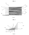
- FIG. 1 is a side view typically illustrating the general structure of a conventional representative stacking type electrode assembly.
- the stacking type electrode assembly 10 is constructed in a structure in which cathodes 20 , each of which has a cathode active material 22 applied to the opposite major surfaces of a cathode current collector 21 , and anodes 30 , each of which has an anode active material 32 applied to the opposite major surfaces of an anode current collector 31 , are sequentially stacked while separators 70 are disposed respectively between the cathodes 20 and the anodes 30 .
- cathode current collectors 21 and the anode current collectors 31 From one-side ends of the cathode current collectors 21 and the anode current collectors 31 protrude pluralities of cathode tabs 41 and anode tabs 51 , to which an active material is not applied, such that the cathode tabs 41 and the anode tabs 51 are electrically connected to a cathode lead 60 and an anode lead (not shown) constituting electrode terminals of a battery (not shown).
- the cathode tabs 41 and the anode tabs 51 are joined in a concentrated state, and are then connected to the cathode lead 60 and the anode lead, respectively. This structure is more clearly illustrated in FIG.
- FIG. 2 is a partially enlarged view typically illustrating the joint portion between the cathode tabs and the cathode lead.
- FIG. 2 illustrates only the joint portion between the cathode tabs and the cathode lead for convenience of description, although this structure is also applied to the joint portion between the anode tabs and the anode lead.
- the cathode tabs 40 are brought into tight contact with each other in the direction indicated by an arrow, and are connected to the cathode lead 60 . Specifically, the cathode tabs 40 are brought into tight contact with the cathode lead 60 adjacent to the lowermost cathode tab 42 such that the cathode tabs 40 are joined to each other with the smallest bending length.
- the length difference occurs at a joint portion A of the cathode tabs 40 between the lowermost cathode tab 42 , which is a short distance from the cathode lead 60 , and the uppermost cathode tab 41 , which is a long distance from the cathode lead 60 , due to the distance difference between the cathode tabs 40 and the cathode lead 60 .
- this length difference also occurs at a joint portion between the anode tabs and the anode lead.
- the areas where the electrode tabs are in contact with the electrode lead are different from each other at the joint portion between the electrode tabs and the electrode lead of the electrode assembly, with the result that the use of electrode leads having more than a necessary size is inevitable.
- the size of the electrode lead is set based on the electrode tab having the largest contact area so as to fix the electrode tabs, the thickness of which is much less than the electrode lead.
- the structural stability of the electrode assembly having the above-described structure is lowered for this reason.
- the end of the electrode lead it is possible to bend the end of the electrode lead to a predetermined angle, the short-distance electrode tab to a large angle, and the long-distance electrode tab to a small angle in order to reduce the length difference between the electrode tabs at the joint portion thereof.
- the size of the joint portion between the electrode tabs and the electrode lead is increased due to the bending, with the result that the electrode assembly may move, when external impacts are applied to the electrode assembly, and therefore, a possibility of the occurrence of a short circuit is strong.
- the thickness of the electrode lead is approximately twice that of a small-sized battery cell, with the result that it is more difficult to apply the above-described structure.
- the present invention has been made to solve the above problems, and other technical problems that have yet to be resolved.
- an object of the present invention to provide an electrode assembly having a structure in which the lengths of electrode tabs at a joint portion between the electrode tabs and an electrode lead are the same while the bending of the electrode tabs is minimized.
- the above and other objects can be accomplished by the provision of a stacking or stacking/folding type electrode assembly of a cathode/separator/anode structure, wherein the electrode assembly is constructed in a structure in which tabs (electrode tabs), having no active material applied thereto, protrude from electrode plates constituting the electrode assembly, electrode leads are located at one-side ends of the stacked electrode tabs such that the electrode leads are electrically connected to the electrode tabs, and protruding lengths of the electrode tabs are gradually increased according to the distances between the electrode leads and the electrode tabs, whereby the lengths of the electrode tabs at joint portions between the electrode tabs and the electrode leads are the same.
- tabs electrode tabs
- the electrode leads are not particularly restricted so long as the electrode leads are made of a material that can be electrically connected to the electrode tabs.
- the electrode leads are made of a metal plate.
- the metal plate may be selected from a group consisting of an aluminum plate, a copper plate, a nickel plate, a copper plate coated with nickel, and a SUS plate.
- the electrode leads are not particularly restricted so long as the electrode leads are constructed in a structure in which the electrode leads are easily connected to the electrode tabs.
- the electrode leads may be formed in the shape of a straight line in vertical section, and the electrode leads are joined to the electrode tabs by welding.
- the electrode leads may be connected to the electrode tabs in various manners.
- the electrode leads are more stably connected to the electrode tabs by welding.
- the welding may include ultrasonic welding, laser welding, and resistance welding.
- the one-side end of the stacked electrode tabs where each electrode lead is preferably located, means the upper-side end of the electrode tab located at the uppermost position in the direction in which the electrode tabs are stacked (the uppermost electrode tab) or the lower-side end of the electrode tab located at the lowermost position in the direction in which the electrode tabs are stacked (the lowermost electrode tab). Consequently, the direction in which the protruding lengths of the electrode tabs are increased may be changed depending upon which side end of the stacked electrode tabs each electrode lead is located at. For example, when each electrode lead is located at the upper-side end of the uppermost electrode tab, it is preferable that the protruding lengths of the electrode tabs be gradually increased from the uppermost electrode tab to the lowermost electrode tab.
- an electrochemical cell including the electrode assembly with the above-stated construction.
- the electrochemical cell is one that provides electricity through an electrochemical reaction.
- the electrochemical cell may be an electrochemical secondary battery or an electrochemical capacitor.
- the electrochemical cell is preferably applied to a lithium secondary battery.
- the secondary battery includes an electrode assembly that can be charged and discharged.
- the secondary battery is constructed in a structure in which an electrode assembly is mounted in a battery case made of a laminate sheet including a metal layer and a resin layer in a sealed state.
- the secondary battery with the above-described structure may be referred to as a pouch-shaped secondary battery.
- the secondary battery is preferably used as a unit cell for high-output, large-capacity battery packs.
- FIG. 1 is a typical view illustrating the general structure of a conventional stacking type electrode assembly
- FIG. 2 is an enlarged view illustrating the connection between cathode tabs, joined to each other in a concentrated state, and a cathode lead of the electrode assembly shown in FIG. 1 ;
- FIG. 3 is a typical view illustrating the structure of a stacking type electrode assembly according to a preferred embodiment of the present invention.
- FIG. 4 is an enlarged view illustrating the connection between cathode tabs, joined to each other in a concentrated state, and a cathode lead of the electrode assembly shown in FIG. 3 .
- FIG. 3 is a typical view illustrating the structure of a stacking type electrode assembly according to a preferred embodiment of the present invention.
- the electrode assembly of FIG. 3 is approximately identical to the conventional electrode assembly, which is being generally used, and therefore, only the characteristics of the present invention will be described hereinafter.
- FIG. 3 illustrates only cathode tabs for convenience of description, although this structure is also applied to anode tabs.
- the electrode assembly 100 includes cathode plates 200 having cathode tabs 300 the protruding lengths of which are different.
- the respective cathode tabs 300 protrude from cathode current collectors 210 while a cathode active material 220 is not applied to the respective cathode tabs 300 .
- the cathode plates 200 are stacked in a structure in which a cathode plate 202 having a cathode tab 302 , the protruding length of which is the smallest is located at the lowermost position, and a cathode plate 201 having a cathode tab 301 , the protruding length of which is the largest is located at the uppermost position, such that the protruding lengths of the cathode tabs 300 are gradually increased from the lowermost position to the uppermost position.
- FIG. 4 is a partially enlarged view typically illustrating the joint portion between the cathode tabs and the cathode lead.
- the cathode tabs 300 are brought into tight contact with each other in the direction indicated by an arrow, and are then connected to the cathode lead 400 .
- the cathode tab 302 located at the lowermost position, is little bent, and the bending angle is gradually increased toward the cathode tab 301 , located at the uppermost position. Consequently, the cathode tabs 300 have the same joint length L 3 at a joint portion B due to the difference between the bending angles, although the cathode tabs 300 have different protruding lengths.
- the joint length L 3 corresponds to the length of the lowermost cathode tab 302 , which is little bent. Consequently, the joint length L 3 is less than the joint length L 1 set based on the lowermost cathode tab 42 having the largest length at the joint portion A, as shown in FIG. 2 .
- the length L 4 of the cathode lead corresponding to the joint length L 3 of the cathode tabs 300 , is also less than the length L 2 of the cathode lead as shown in FIG. 2 .
- the cathode tabs 300 are bent based on the lowermost cathode tab 302 , which is little bent, and therefore, the cathode tabs 300 have the smallest bending length L 5 .
- a cathode active material containing lithium and an anode active material containing graphite were applied to opposite major surfaces of an aluminum foil and a copper foil, respectively, and then the aluminum foil and the copper foil were cut such that tab parts, of the cut aluminum foils and the cut copper foils, to which the active materials were not applied, had gradually increased lengths. Subsequently, the cut aluminum foils and the cut copper foils were stacked using separators in the structure shown in FIG. 3 . After that, the tab parts of the cut aluminum foils and the cut copper foils were brought into tight contact with each other, as shown in FIG. 4 , in the direction in which the cut aluminum foils and the cut copper foils were stacked, and were connected to corresponding electrode leads to manufacture an electrode assembly.
- An electrode assembly was manufactured in the same method as Example 1 except that the aluminum foil and the copper foil were cut such that tab parts, of the cut aluminum foils and the cut copper foils, to which the active materials were not applied, had the same length.
- the tab ends of the electrode assembly manufactured according to Example 1 and Comparative example 1 were observed, using a microscope, to inspect the surface state thereof.
- the burrs damage the corresponding regions of the battery case, during the assembly or the use of a battery, with the result that a short circuit may occur in the battery or an electrolyte may leak from the battery.
- the electrode assembly is constructed in a structure in which the lengths of electrode tabs at a joint portion between the electrode tabs and an electrode lead are the same while the bending of the electrode tabs is minimized. Furthermore, the electrode assembly is constructed in a structure in which the joining between the electrode tabs and the electrode lead is stably performed while the size of the electrode lead is small.
Landscapes
- Engineering & Computer Science (AREA)
- Power Engineering (AREA)
- Chemical & Material Sciences (AREA)
- Chemical Kinetics & Catalysis (AREA)
- Electrochemistry (AREA)
- General Chemical & Material Sciences (AREA)
- Microelectronics & Electronic Packaging (AREA)
- Materials Engineering (AREA)
- Manufacturing & Machinery (AREA)
- Connection Of Batteries Or Terminals (AREA)
- Electric Double-Layer Capacitors Or The Like (AREA)
- Secondary Cells (AREA)
- Sealing Battery Cases Or Jackets (AREA)
Abstract
Description
Claims (7)
Applications Claiming Priority (3)
| Application Number | Priority Date | Filing Date | Title |
|---|---|---|---|
| KR1020060068823A KR100848788B1 (en) | 2006-07-24 | 2006-07-24 | Electrode Assembly Having Electrode Tabs of the Same Size in Joint Portion thereof and Electrochemical Cell Containing the Same |
| KR10-2006-0068823 | 2006-07-24 | ||
| PCT/KR2007/003411 WO2008013371A1 (en) | 2006-07-24 | 2007-07-14 | Electrode assembly having electrode tabs of the same size in joint portion thereof and electrochemical cell containing the same |
Publications (2)
| Publication Number | Publication Date |
|---|---|
| US20100028770A1 US20100028770A1 (en) | 2010-02-04 |
| US8846243B2 true US8846243B2 (en) | 2014-09-30 |
Family
ID=38981660
Family Applications (1)
| Application Number | Title | Priority Date | Filing Date |
|---|---|---|---|
| US12/309,548 Active 2028-03-07 US8846243B2 (en) | 2006-07-24 | 2007-07-14 | Electrode assembly having electrode tabs of the same size in joint portion thereof and electrochemical cell containing the same |
Country Status (5)
| Country | Link |
|---|---|
| US (1) | US8846243B2 (en) |
| JP (2) | JP2008027891A (en) |
| KR (1) | KR100848788B1 (en) |
| CN (2) | CN101517807A (en) |
| WO (1) | WO2008013371A1 (en) |
Cited By (3)
| Publication number | Priority date | Publication date | Assignee | Title |
|---|---|---|---|---|
| US10193125B2 (en) | 2015-09-24 | 2019-01-29 | Samsung Sdi Co., Ltd. | Electrode assembly and secondary battery including the same |
| US10411242B2 (en) | 2015-09-23 | 2019-09-10 | Samsung Sdi Co., Ltd. | Secondary battery |
| US12074344B2 (en) | 2020-06-25 | 2024-08-27 | Medtronic, Inc. | Shaped rechargeable battery electronic interconnect |
Families Citing this family (30)
| Publication number | Priority date | Publication date | Assignee | Title |
|---|---|---|---|---|
| US7875382B2 (en) * | 2008-08-28 | 2011-01-25 | International Battery, Inc. | Battery |
| KR101101046B1 (en) * | 2009-12-01 | 2011-12-29 | 삼성에스디아이 주식회사 | Electrode assembly and secondary battery having the same |
| US20110206976A1 (en) * | 2010-02-19 | 2011-08-25 | Kyung-Mo Yoo | Electrode assembly and secondary battery using the same |
| DE102010019504A1 (en) | 2010-05-06 | 2011-11-10 | Bayer Materialscience Ag | Polyisocyanate prepolymers and their use |
| KR20120031606A (en) * | 2010-09-27 | 2012-04-04 | 주식회사 엘지화학 | Electrode lead whose protection layer for anti-corrosion is selectively formed, and secondary battery comprising thereof |
| WO2013002621A2 (en) | 2011-06-30 | 2013-01-03 | 주식회사 엘지화학 | Secondary battery having improved contact resistance |
| KR101361113B1 (en) | 2011-07-13 | 2014-02-13 | 주식회사 엘지화학 | Battery Module of Improved Connection Reliability and Battery Pack Employed with the Same |
| WO2014027606A1 (en) * | 2012-08-14 | 2014-02-20 | 株式会社 豊田自動織機 | Electrical storage device |
| KR101482385B1 (en) * | 2013-02-08 | 2015-01-20 | 주식회사 엘지화학 | Stepwise Cell Assembly |
| US20150136840A1 (en) * | 2013-11-21 | 2015-05-21 | Medtronic, Inc. | Method of joining stacks of thin metal foil layers |
| JP2016039041A (en) * | 2014-08-07 | 2016-03-22 | 株式会社Gsユアサ | Power storage element and manufacturing method for the same |
| WO2016056875A2 (en) | 2014-10-10 | 2016-04-14 | 주식회사 엘지화학 | Electrode assembly and method for manufacturing same |
| JP6415959B2 (en) * | 2014-12-11 | 2018-10-31 | 株式会社東芝 | Electrode group, battery, and battery manufacturing method |
| DE102015201658A1 (en) | 2015-01-30 | 2016-08-04 | Robert Bosch Gmbh | Battery cell and battery system |
| DE102015201655A1 (en) | 2015-01-30 | 2016-08-04 | Robert Bosch Gmbh | Battery cell and battery system |
| DE102015201652A1 (en) | 2015-01-30 | 2016-08-04 | Robert Bosch Gmbh | Battery cell, method of manufacturing an electrode coil for a battery cell and battery system |
| KR101870314B1 (en) | 2015-04-16 | 2018-06-22 | 주식회사 엘지화학 | Electrode Assembly Comprising Coupling Part between Electrode Tabs and Electrode Lead Located at Space Portion |
| KR20180004769A (en) * | 2015-05-06 | 2018-01-12 | 슈크라 게라테바우 게엠베하 | Method and apparatus for processing a textile cushion body |
| KR102288544B1 (en) | 2015-06-29 | 2021-08-11 | 삼성에스디아이 주식회사 | Secondary Battery And Fabricating Method Thereof |
| KR102042999B1 (en) * | 2016-02-05 | 2019-11-11 | 주식회사 엘지화학 | Method for Preparation of Stack and Folding-typed Electrode Assembly Having Electrode Taps with Various-Sized |
| KR102101010B1 (en) * | 2016-03-08 | 2020-04-14 | 주식회사 엘지화학 | Electrode assembly and secondary battery comprising the same |
| KR102289692B1 (en) * | 2016-09-06 | 2021-08-13 | 삼성에스디아이 주식회사 | The methode of an electrode tab and a rechargeable battery |
| KR102234993B1 (en) * | 2016-12-21 | 2021-04-01 | 주식회사 엘지화학 | Battery Cell and Manufacturing Method thereof |
| CN113871807A (en) * | 2020-06-30 | 2021-12-31 | 比亚迪股份有限公司 | Battery and battery pack |
| CN111933883B (en) * | 2020-08-06 | 2022-10-14 | 东莞市万连实业有限公司 | Adapter sheet for high-capacity battery and preparation method thereof |
| CN114204220B (en) * | 2020-08-31 | 2023-04-07 | 比亚迪股份有限公司 | Battery cell, battery and battery pack |
| CN112117497A (en) * | 2020-10-09 | 2020-12-22 | 昆山聚创新能源科技有限公司 | Battery cell and battery cell forming method |
| JP7523315B2 (en) | 2020-10-27 | 2024-07-26 | 日産自動車株式会社 | All-solid-state battery |
| WO2022133710A1 (en) * | 2020-12-22 | 2022-06-30 | 宁德新能源科技有限公司 | Electrochemical device and electrical device |
| WO2023096469A1 (en) * | 2021-11-29 | 2023-06-01 | 주식회사 엘지에너지솔루션 | Electrode tab welding apparatus, electrode tab welding method, and secondary battery |
Citations (14)
| Publication number | Priority date | Publication date | Assignee | Title |
|---|---|---|---|---|
| US4098966A (en) * | 1977-11-14 | 1978-07-04 | General Motors Corporation | Welded battery elements and process |
| JPH0752827A (en) | 1993-08-09 | 1995-02-28 | Nissan Motor Co Ltd | Instrument panel |
| JPH08250103A (en) | 1995-03-13 | 1996-09-27 | Nippondenso Co Ltd | Manufacture of square battery |
| JPH11167913A (en) | 1997-12-04 | 1999-06-22 | Matsushita Electric Ind Co Ltd | Connecting method for stacked electrodes for battery and the battery |
| US6423442B1 (en) | 1999-03-04 | 2002-07-23 | Wilson Greatbatch Ltd. | Cell stack design with bi-directionally wound slotted electrodes and method for making |
| JP2003123743A (en) | 2001-10-12 | 2003-04-25 | Sony Corp | Solid electrolyte battery and method of manufacturing the same |
| US6617074B1 (en) * | 1999-06-30 | 2003-09-09 | Mitsubishi Materials Corporation | Lithium ion polymer secondary battery and gelatinous polymer electrolyte for sheet battery |
| KR20030095519A (en) | 2002-06-12 | 2003-12-24 | 주식회사 코캄엔지니어링 | Method for treating eletcrode tab of crude cell for lithium secondary battery & crude cell according to the method & lithium secondary battery therefrom |
| US20040038124A1 (en) * | 2002-08-22 | 2004-02-26 | Nissan Motor Co., Ltd | Laminate cell, assembled battery, battery module and electric vehicle |
| US20040038122A1 (en) * | 2002-08-26 | 2004-02-26 | Nissan Motor Co., Ltd. | Laminate cell, assembled battery, battery module and electric vehicle |
| US20040106038A1 (en) * | 2002-08-05 | 2004-06-03 | Nissan Motor Co., Ltd. | Automobile cell and related method |
| US6849358B2 (en) | 2001-04-06 | 2005-02-01 | Ngk Spark Plug Co., Ltd. | Lithium ion battery |
| US20070117020A1 (en) * | 2005-11-18 | 2007-05-24 | Actuant Corporation | Storage battery electrodes with integral conductors |
| KR20080021271A (en) | 2006-09-04 | 2008-03-07 | 주식회사 엘지화학 | Battery cell with small groove at surface and battery pack including the same |
Family Cites Families (4)
| Publication number | Priority date | Publication date | Assignee | Title |
|---|---|---|---|---|
| JPH08111216A (en) * | 1994-10-12 | 1996-04-30 | Sanyo Electric Co Ltd | Manufacture of battery |
| KR20040048295A (en) * | 2002-12-02 | 2004-06-07 | 히다치 막셀 가부시키가이샤 | Battery |
| JP5219340B2 (en) * | 2006-03-08 | 2013-06-26 | 三洋電機株式会社 | Negative electrode for lithium secondary battery, method for producing the same, and lithium secondary battery |
| JP2015123743A (en) * | 2013-12-27 | 2015-07-06 | 株式会社リコー | Solid molding system, solid information processing program, and solid object production method |
-
2006
- 2006-07-24 KR KR1020060068823A patent/KR100848788B1/en active IP Right Grant
-
2007
- 2007-03-28 JP JP2007084089A patent/JP2008027891A/en not_active Revoked
- 2007-07-14 CN CNA2007800345062A patent/CN101517807A/en active Pending
- 2007-07-14 WO PCT/KR2007/003411 patent/WO2008013371A1/en active Application Filing
- 2007-07-14 US US12/309,548 patent/US8846243B2/en active Active
- 2007-07-14 CN CN201110411278.4A patent/CN102522519B/en active Active
-
2012
- 2012-01-25 JP JP2012013361A patent/JP5846932B2/en active Active
Patent Citations (14)
| Publication number | Priority date | Publication date | Assignee | Title |
|---|---|---|---|---|
| US4098966A (en) * | 1977-11-14 | 1978-07-04 | General Motors Corporation | Welded battery elements and process |
| JPH0752827A (en) | 1993-08-09 | 1995-02-28 | Nissan Motor Co Ltd | Instrument panel |
| JPH08250103A (en) | 1995-03-13 | 1996-09-27 | Nippondenso Co Ltd | Manufacture of square battery |
| JPH11167913A (en) | 1997-12-04 | 1999-06-22 | Matsushita Electric Ind Co Ltd | Connecting method for stacked electrodes for battery and the battery |
| US6423442B1 (en) | 1999-03-04 | 2002-07-23 | Wilson Greatbatch Ltd. | Cell stack design with bi-directionally wound slotted electrodes and method for making |
| US6617074B1 (en) * | 1999-06-30 | 2003-09-09 | Mitsubishi Materials Corporation | Lithium ion polymer secondary battery and gelatinous polymer electrolyte for sheet battery |
| US6849358B2 (en) | 2001-04-06 | 2005-02-01 | Ngk Spark Plug Co., Ltd. | Lithium ion battery |
| JP2003123743A (en) | 2001-10-12 | 2003-04-25 | Sony Corp | Solid electrolyte battery and method of manufacturing the same |
| KR20030095519A (en) | 2002-06-12 | 2003-12-24 | 주식회사 코캄엔지니어링 | Method for treating eletcrode tab of crude cell for lithium secondary battery & crude cell according to the method & lithium secondary battery therefrom |
| US20040106038A1 (en) * | 2002-08-05 | 2004-06-03 | Nissan Motor Co., Ltd. | Automobile cell and related method |
| US20040038124A1 (en) * | 2002-08-22 | 2004-02-26 | Nissan Motor Co., Ltd | Laminate cell, assembled battery, battery module and electric vehicle |
| US20040038122A1 (en) * | 2002-08-26 | 2004-02-26 | Nissan Motor Co., Ltd. | Laminate cell, assembled battery, battery module and electric vehicle |
| US20070117020A1 (en) * | 2005-11-18 | 2007-05-24 | Actuant Corporation | Storage battery electrodes with integral conductors |
| KR20080021271A (en) | 2006-09-04 | 2008-03-07 | 주식회사 엘지화학 | Battery cell with small groove at surface and battery pack including the same |
Non-Patent Citations (1)
| Title |
|---|
| Office Action from Korean Patent Application No. 10-2006-0068823 issued Jan. 19, 20100. |
Cited By (3)
| Publication number | Priority date | Publication date | Assignee | Title |
|---|---|---|---|---|
| US10411242B2 (en) | 2015-09-23 | 2019-09-10 | Samsung Sdi Co., Ltd. | Secondary battery |
| US10193125B2 (en) | 2015-09-24 | 2019-01-29 | Samsung Sdi Co., Ltd. | Electrode assembly and secondary battery including the same |
| US12074344B2 (en) | 2020-06-25 | 2024-08-27 | Medtronic, Inc. | Shaped rechargeable battery electronic interconnect |
Also Published As
| Publication number | Publication date |
|---|---|
| KR100848788B1 (en) | 2008-07-30 |
| JP5846932B2 (en) | 2016-01-20 |
| WO2008013371A1 (en) | 2008-01-31 |
| US20100028770A1 (en) | 2010-02-04 |
| JP2012124171A (en) | 2012-06-28 |
| CN102522519B (en) | 2015-09-16 |
| CN102522519A (en) | 2012-06-27 |
| KR20080009351A (en) | 2008-01-29 |
| CN101517807A (en) | 2009-08-26 |
| JP2008027891A (en) | 2008-02-07 |
Similar Documents
| Publication | Publication Date | Title |
|---|---|---|
| US8846243B2 (en) | Electrode assembly having electrode tabs of the same size in joint portion thereof and electrochemical cell containing the same | |
| US10026944B2 (en) | Electrode assembly having tab-lead joint portion of minimized resistance difference between electrodes and electrochemical cell containing the same | |
| US10056577B2 (en) | Battery cell of novel structure | |
| US8034478B2 (en) | Secondary battery of improved safety | |
| US9478773B2 (en) | Battery cell of asymmetric structure and battery pack employed with the same | |
| US8669003B2 (en) | Lithium secondary battery improved safety and capacity | |
| US8673476B2 (en) | Electrode assembly having stable lead-tap joint and electrochemical cell containing them | |
| US20220416374A1 (en) | Apparatus and Method for Bending Electrode Tab | |
| WO2006121267A1 (en) | Three-dimensional electrode terminal for pouch-typed battery | |
| EP3168918B1 (en) | Electrode assembly wound in both directions, and lithium secondary battery comprising same | |
| US20130122355A1 (en) | Rechargeable battery | |
| KR20210011813A (en) | The Case For Secondary Battery And The Pouch Type Secondary Battery | |
| EP3993143A1 (en) | Pouch-type battery case and pouch-type secondary battery | |
| US20140023913A1 (en) | Prismatic secondary battery | |
| KR20200058173A (en) | Secondary battery | |
| KR102704540B1 (en) | The Case For Secondary Battery And The Pouch Type Secondary Battery | |
| KR20210098756A (en) | The Case For Secondary Battery And The Secondary Battery | |
| KR20210076770A (en) | The Case For Secondary Battery And The Pouch Type Secondary Battery | |
| KR20210002995A (en) | The Case For Secondary Battery And The Pouch Type Secondary Battery | |
| KR20210037460A (en) | The Battery Case For Secondary Battery And The Method For Manufacturing Thereof | |
| KR20200095914A (en) | Cylindrical secondary battery and method manufacturing the same |
Legal Events
| Date | Code | Title | Description |
|---|---|---|---|
| AS | Assignment |
Owner name: LG CHEM, LTD.,KOREA, REPUBLIC OF Free format text: ASSIGNMENT OF ASSIGNORS INTEREST;ASSIGNORS:RYU, JI HEON;LEE, EUN JU;CHOI, JEONG HEE;AND OTHERS;SIGNING DATES FROM 20090313 TO 20090718;REEL/FRAME:023190/0564 Owner name: LG CHEM, LTD.,KOREA, REPUBLIC OF Free format text: ASSIGNMENT OF ASSIGNORS INTEREST;ASSIGNORS:RYU, JI HEON;LEE, EUN JU;CHOI, JEONG HEE;AND OTHERS;SIGNING DATES FROM 20090313 TO 20090718;REEL/FRAME:023190/0547 Owner name: LG CHEM, LTD., KOREA, REPUBLIC OF Free format text: ASSIGNMENT OF ASSIGNORS INTEREST;ASSIGNORS:RYU, JI HEON;LEE, EUN JU;CHOI, JEONG HEE;AND OTHERS;SIGNING DATES FROM 20090313 TO 20090718;REEL/FRAME:023190/0547 Owner name: LG CHEM, LTD., KOREA, REPUBLIC OF Free format text: ASSIGNMENT OF ASSIGNORS INTEREST;ASSIGNORS:RYU, JI HEON;LEE, EUN JU;CHOI, JEONG HEE;AND OTHERS;SIGNING DATES FROM 20090313 TO 20090718;REEL/FRAME:023190/0564 |
|
| FEPP | Fee payment procedure |
Free format text: PAYOR NUMBER ASSIGNED (ORIGINAL EVENT CODE: ASPN); ENTITY STATUS OF PATENT OWNER: LARGE ENTITY Free format text: PAYER NUMBER DE-ASSIGNED (ORIGINAL EVENT CODE: RMPN); ENTITY STATUS OF PATENT OWNER: LARGE ENTITY |
|
| STCF | Information on status: patent grant |
Free format text: PATENTED CASE |
|
| MAFP | Maintenance fee payment |
Free format text: PAYMENT OF MAINTENANCE FEE, 4TH YEAR, LARGE ENTITY (ORIGINAL EVENT CODE: M1551) Year of fee payment: 4 |
|
| AS | Assignment |
Owner name: LG ENERGY SOLUTION, LTD., KOREA, REPUBLIC OF Free format text: ASSIGNMENT OF ASSIGNORS INTEREST;ASSIGNOR:LG CHEM, LTD.;REEL/FRAME:058295/0068 Effective date: 20211027 |
|
| MAFP | Maintenance fee payment |
Free format text: PAYMENT OF MAINTENANCE FEE, 8TH YEAR, LARGE ENTITY (ORIGINAL EVENT CODE: M1552); ENTITY STATUS OF PATENT OWNER: LARGE ENTITY Year of fee payment: 8 |