US8842782B2 - Apparatus and method for decoding a received signal - Google Patents
Apparatus and method for decoding a received signal Download PDFInfo
- Publication number
- US8842782B2 US8842782B2 US13/468,133 US201213468133A US8842782B2 US 8842782 B2 US8842782 B2 US 8842782B2 US 201213468133 A US201213468133 A US 201213468133A US 8842782 B2 US8842782 B2 US 8842782B2
- Authority
- US
- United States
- Prior art keywords
- transmission
- received signal
- filter
- multiple input
- input multiple
- Prior art date
- Legal status (The legal status is an assumption and is not a legal conclusion. Google has not performed a legal analysis and makes no representation as to the accuracy of the status listed.)
- Expired - Fee Related, expires
Links
Images


Classifications
-
- H—ELECTRICITY
- H04—ELECTRIC COMMUNICATION TECHNIQUE
- H04B—TRANSMISSION
- H04B7/00—Radio transmission systems, i.e. using radiation field
- H04B7/02—Diversity systems; Multi-antenna system, i.e. transmission or reception using multiple antennas
- H04B7/04—Diversity systems; Multi-antenna system, i.e. transmission or reception using multiple antennas using two or more spaced independent antennas
- H04B7/08—Diversity systems; Multi-antenna system, i.e. transmission or reception using multiple antennas using two or more spaced independent antennas at the receiving station
- H04B7/0868—Hybrid systems, i.e. switching and combining
- H04B7/0871—Hybrid systems, i.e. switching and combining using different reception schemes, at least one of them being a diversity reception scheme
-
- H—ELECTRICITY
- H04—ELECTRIC COMMUNICATION TECHNIQUE
- H04L—TRANSMISSION OF DIGITAL INFORMATION, e.g. TELEGRAPHIC COMMUNICATION
- H04L1/00—Arrangements for detecting or preventing errors in the information received
- H04L1/004—Arrangements for detecting or preventing errors in the information received by using forward error control
- H04L1/0045—Arrangements at the receiver end
- H04L1/0046—Code rate detection or code type detection
-
- H—ELECTRICITY
- H04—ELECTRIC COMMUNICATION TECHNIQUE
- H04L—TRANSMISSION OF DIGITAL INFORMATION, e.g. TELEGRAPHIC COMMUNICATION
- H04L1/00—Arrangements for detecting or preventing errors in the information received
- H04L1/004—Arrangements for detecting or preventing errors in the information received by using forward error control
- H04L1/0045—Arrangements at the receiver end
- H04L1/0047—Decoding adapted to other signal detection operation
- H04L1/0048—Decoding adapted to other signal detection operation in conjunction with detection of multiuser or interfering signals, e.g. iteration between CDMA or MIMO detector and FEC decoder
-
- H—ELECTRICITY
- H04—ELECTRIC COMMUNICATION TECHNIQUE
- H04L—TRANSMISSION OF DIGITAL INFORMATION, e.g. TELEGRAPHIC COMMUNICATION
- H04L25/00—Baseband systems
- H04L25/02—Details ; arrangements for supplying electrical power along data transmission lines
- H04L25/03—Shaping networks in transmitter or receiver, e.g. adaptive shaping networks
- H04L25/03006—Arrangements for removing intersymbol interference
- H04L25/03178—Arrangements involving sequence estimation techniques
-
- H—ELECTRICITY
- H04—ELECTRIC COMMUNICATION TECHNIQUE
- H04L—TRANSMISSION OF DIGITAL INFORMATION, e.g. TELEGRAPHIC COMMUNICATION
- H04L25/00—Baseband systems
- H04L25/02—Details ; arrangements for supplying electrical power along data transmission lines
- H04L25/03—Shaping networks in transmitter or receiver, e.g. adaptive shaping networks
- H04L25/03006—Arrangements for removing intersymbol interference
- H04L2025/0335—Arrangements for removing intersymbol interference characterised by the type of transmission
- H04L2025/03426—Arrangements for removing intersymbol interference characterised by the type of transmission transmission using multiple-input and multiple-output channels
-
- H—ELECTRICITY
- H04—ELECTRIC COMMUNICATION TECHNIQUE
- H04L—TRANSMISSION OF DIGITAL INFORMATION, e.g. TELEGRAPHIC COMMUNICATION
- H04L25/00—Baseband systems
- H04L25/02—Details ; arrangements for supplying electrical power along data transmission lines
- H04L25/0202—Channel estimation
- H04L25/024—Channel estimation channel estimation algorithms
- H04L25/0242—Channel estimation channel estimation algorithms using matrix methods
- H04L25/0248—Eigen-space methods
Definitions
- German Patent Application, Application No. 10 2011 054 913.7 which was filed on Oct. 28, 2011, is incorporated herein in its entirety by reference.
- the present invention relates to an apparatus and method for filtering a received signal and, in particular, to an apparatus and method for filtering a received signal, wherein the received signal has been transmitted by conducting a transmission being either a single-user Multiple Input Multiple Output transmission or a multi-user Multiple Input Multiple Output transmission.
- LTE Long-Term Evolution
- 3GPP Third Generation Partnership Project
- E-UTRA Evolved Universal Terrestrial Radio Access
- R-UTRA Physical Channels and Modulation
- 3GPP 36.213 “Evolved Universal Terrestrial Radio Access (E-UTRA); Physical layer procedures (Release 8)”, Sophia Antipolis, 2009, which are hereby incorporated by reference.
- the transmission modes can be divided into two groups.
- the first group provides feedback in terms of channel state information (CSI) from a user equipment (UE) to the evolved NodeB (eNodeB) and is therefore named “closed-loop” transmission.
- the other group provides no feedback and is named “open-loop” transmission.
- LTE provides transmission modes, where the eNodeB groups a number of UEs and serves them using the same time-frequency blocks. These transmission modes are called multi-user Multiple Input Multiple Output (MU-MIMO).
- MU-MIMO Multi-user Multiple Input Multiple Output
- the eNodeB performs digital beamforming using a finite set of precoding vectors depending on the number of transmit antenna ports. This approach is particularly advantageous in a dense cell with rare resources. Instead of waiting for free resource blocks, the eNodeB may group UEs and allocate the same resource blocks to prevent waiting periods and therefore increases spectral efficiency. The main drawback of this approach is the increase of mutual interference at each of these two UEs.
- the signal to both UEs is precoded, summed up and transmitted by the eNodeB, so each user equipment is responsible to filter out its own signal.
- the eNodeB does not find an appropriate candidate for grouping, only a single UE is served by the eNodeB.
- the UE is unaware if there is another co-scheduled UE, as far as the eNodeB does not provide this information to save transmission bandwidth.
- the eNodeB does not provide any explicit information on whether the transmission is either a single user-(SU) or multi user-(MU) MIMO transmission.
- UEs operating in MU-MIMO scenarios may always choose an MMSE (Minimum-Mean-Square-Error) receive filter, although there may be no co-scheduled UE available. Although this receive filter does not fit best, it provides acceptable results, but performs worse when no co-scheduled UE is available.
- MMSE Minimum-Mean-Square-Error
- an apparatus for decoding a received signal comprising a detector and a filter application unit.
- the detector is configured to detect whether the transmission is a SU-MIMO transmission or a MU-MIMO transmission.
- the filter application unit is configured to apply either a first receive filter or a second different receive filter on the received signal depending on whether the transmission is the SU-MIMO transmission or the MU-MIMO transmission.
- an apparatus for filtering a received signal to obtain a filtered signal comprising a detector and a filter application unit.
- the detector is configured to detect whether the transmission is either a single-user Multiple Input Multiple Output transmission or a multi-user Multiple Input Multiple Output transmission.
- the filter application unit is configured to apply a first receive filter with a first filter characteristic on the received signal to obtain the filtered signal when the transmission is the single-user Multiple Input Multiple Output transmission.
- the filter application unit is configured to apply a second receive filter with a second filter characteristic on the received signal to obtain the filtered signal when the transmission is the multi-user Multiple Input Multiple Output transmission.
- Embodiments are based on the finding that a first receive filter with a first filter characteristic should be applied for decoding the received signal when the transmission is a single-user Multiple Input Multiple Output transmission, and that a second different receive filter with a second different filter characteristic should be applied for decoding the received signal when the transmission is a multi-user Multiple Input Multiple Output transmission.
- the correct choice of the receive filter depends on the environment, e.g. whether the transmission is either SU- or MU-MIMO.
- the UE is operating in multi-user MIMO mode, e.g. Transmission Mode 5 in LTE, there may be no appropriate UE for co-scheduling available, so MU-MIMO degrades to SU-MIMO.
- the eNodeB does not provide any information if either SU- or MU-MIMO is being currently used, it is up to the UE to distinguish between these two modes. Choosing the wrong receiver results in degradation in terms of Bit Error Ratio (BER).
- BER Bit Error Ratio
- the transmission is a single-user Multiple Input Multiple Output transmission this may, e.g., mean that the received signal comprises first signal portions for a first user equipment, but not also different second signal portions for a different second user equipment.
- the transmission is a multi-user Multiple Input Multiple Output transmission this may, e.g., mean that the received signal comprises first signal portions for a first user equipment and different second signal portions for a different second user equipment.
- a criterion is provided which allows to switch between two different receivers, depending on the availability of the co-scheduled UE.
- the first receiver may be a Maximum-Ratio-Combiner (MRC) receiver and the second receiver may be a Minimum-Mean-Square-Error (MMSE) receiver.
- MRC Maximum-Ratio-Combiner
- MMSE Minimum-Mean-Square-Error
- an IRC, SIC or ML receiver e.g. Sphere, being adapted for SU-MIMO can be used in the SU-MIMO case
- an IRC, SIC or ML receiver e.g. Sphere, being adapted for MU-MIMO can be used in the MU-MIMO case
- IRC Interference Rejection Combiner
- SIC Successive Interference Cancel
- ML Maximum Likelihood
- a mobile communication device comprises a baseband processor, an antenna and an apparatus for filtering a received signal, wherein the received signal has been transmitted by conducting a transmission.
- the apparatus for filtering the received signal comprises a detector and a filter application unit.
- the detector is configured to detect whether the transmission is either a single-user Multiple Input Multiple Output transmission or a multi-user Multiple Input Multiple Output transmission.
- the filter application unit is configured to apply a first receive filter with a first filter characteristic on the received signal to obtain the filtered signal when the transmission is the single-user Multiple Input Multiple Output transmission.
- the filter application unit is configured to apply a second receive filter with a second filter characteristic on the received signal to obtain the filtered signal when the transmission is the multi-user Multiple Input Multiple Output transmission.
- a method for filtering a received signal to obtain a filtered signal comprises detecting whether the transmission is either a single-user Multiple Input Multiple Output transmission or a multi-user Multiple Input Multiple Output transmission, and applying on the received signal either a first receive filter with a first filter characteristic when the transmission is the single-user Multiple Input Multiple Output transmission, or a second receive filter with a second filter characteristic when the transmission is the multi-user Multiple Input Multiple Output transmission, to obtain the filtered signal.
- FIG. 1 illustrates an apparatus for decoding a received signal according to an embodiment
- FIG. 2 illustrates an apparatus for decoding a received signal according to another embodiment
- FIG. 3 illustrates an apparatus for decoding a received signal according to a further embodiment
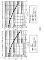
- FIG. 4 illustrates BER over SNR for SU-MIMO and MU-MIMO with different pairing probabilities according to an embodiment
- FIG. 5 illustrates BER over SNR for SU-MIMO and MU-MIMO with different pairing probabilities according to another embodiment
- FIG. 6 illustrates BER over SNR for SU-MIMO and MU-MIMO with different pairing probabilities according to a further embodiment
- FIG. 7 illustrates BER over SNR for SU-MIMO and MU-MIMO with different probabilities and two receive antennas according to another embodiment.
- FIG. 1 illustrates an apparatus for filtering a received signal to obtain a filtered signal, wherein the received signal has been transmitted by conducting a transmission.
- the apparatus comprises a detector 110 and a filter application unit 120 .
- the detector 110 is configured to detect whether the transmission is either a single-user Multiple Input Multiple Output transmission or a multi-user Multiple Input Multiple Output transmission by examining the received signal.
- the detector 110 is configured to inform the filter application unit on whether the transmission is a single-user Multiple Input Multiple Output transmission or whether the transmission is a multi-user Multiple Input Multiple Output transmission. If the transmission is a single-user Multiple Input Multiple Output transmission this may, e.g., mean that the received signal comprises first signal portions for a first user equipment, but not also different second signal portions for a different second user equipment. If the transmission is a multi-user Multiple Input Multiple Output transmission this may, e.g., mean that the received signal comprises first signal portions for a first user equipment and different second signal portions for a different second user equipment.
- the filter application unit 120 is configured to apply a first receive filter with a first filter characteristic on the received signal when the transmission is a single-user Multiple Input Multiple Output transmission. Moreover, the filter application unit 120 is configured to apply a second receive filter with a second filter characteristic on the received signal when the transmission is the multi-user Multiple Input Multiple Output transmission. For this purpose, the detector 110 passes the information about the detected transmission to the filter application unit 120 . By applying either the first receive filter or the second receive filter on the received signal, the filter application unit 120 obtains the decoded signal.
- the provided concepts may be applied for all MU-MIMO transmission modes, e.g. TM5 in LTE and TM9 in LTE-Advanced.
- the special feature of MU-MIMO transmission modes is used to transmit a single layer data stream to at least two spatially separated UEs, using the same time-frequency resource blocks.
- UE-1 is the target UE, where the co-scheduled UE, UE-2, is aimed to be the interfering UE. This scenario is symmetric.
- the second precoding vector p j has been recommended by the co-scheduled UE.
- the symbols d 1 and d 2 have the same modulation order.
- the recommended modulation orders ⁇ 4, 16, 64 ⁇ -QAM are employed.
- the symbols and elements of the noise vector are stochastically independent and identically distributed (i.i.d.).
- H 1 p i and H 1 p j For notational simplicity we denote the matrix-vector product H 1 p i and H 1 p j by g 1 and d 2 , respectively.
- either the Maximum-Ratio-Combiner (MRC) receiver or the Minimum-Mean-Square-Error (MMSE) receiver is applied on the received signal.
- MRC Maximum-Ratio-Combiner
- MMSE Minimum-Mean-Square-Error
- an MRC receiver is applied:
- m _ MRC H g _ 1 H g _ 1 H ⁇ g _ 1 , ( 3 ) which maximizes the post-SNR, see Bai et al., “Receiver Performance in MU-MIMO Transmission in LTE”, ICWMC'11, Germany, June 2011, which hereby incorporated by reference in its entirety.
- MMSE receiver in a MU-MIMO scenario, where a co-scheduled user equipment causes interference, a MMSE receiver is employed.
- the MMSE receiver may be defined according to the formula:
- m _ MMSE H g _ 1 H ⁇ R _ ⁇ _ - 1 g _ 1 H ⁇ R _ ⁇ - 1 ⁇ g _ 1 ( 4 )
- the covariance matrix R ⁇ is a function of the mutual interference caused by the co-scheduled UE plus noise.
- ⁇ g 2 d 2 +n 1
- ⁇ d is either estimated, signaled by the network or a priory known. E.g., for LTE until Release 8, ⁇ d is either estimated or signaled by the network, e.g. as a power offset from a cell specific reference signal. For LTE starting from Release 9, ⁇ d is equal to one.
- FIG. 2 An adaptive switch is depicted in FIG. 2 .
- the switch of FIG. 2 is configured to switch depending on whether the transmission is a SU-MIMO or a MU-MIMO transmission. It is differentiated, if a co-scheduled user equipment is present or not. In case of no co-scheduled user equipment, the switch is in the upper position, so the user equipment employs an MRC filter. If the presence of the co-scheduled UE has been detected, the switch flips to the lower position and a MMSE filter will be used. Again, the structure of both, MRC and MMSE receive filters need not be changed. The adaptive switch behaves like a stage before the receive filter.
- y 1 d 1 g 1 + ⁇ , (6) where interference plus noise is represented by ⁇ .
- Each UE knows its own channel and precoding vector.
- the interference plus noise covariance matrix R ⁇ can be obtained by
- ⁇ ⁇ contains N r ⁇ 1 identical eigenvalues ⁇ n 2 and one eigenvalue ⁇ interf 2 + ⁇ n 2 > ⁇ n 2 .
- FIG. 2 the approach how to decide, whether the co-scheduled UE is available, is depicted.
- ⁇ th of FIG. 2 is defined according to:
- ⁇ th max ⁇ ⁇ [ ⁇ _ ⁇ ] ii ⁇ ⁇ n 2 ⁇ ⁇ ⁇ 1 , co ⁇ - ⁇ scheduled ⁇ ⁇ UE ⁇ ⁇ is ⁇ ⁇ not ⁇ ⁇ available > 1 , co ⁇ - ⁇ scheduled ⁇ ⁇ UE ⁇ ⁇ is ⁇ ⁇ available . ( 11 )
- the analytic expression for the adaptive switch is provided.
- Either the MRC or the MMSE receiver is chosen, depending on whether ⁇ th ⁇ 1 or whether ⁇ th >1, respectively.
- m MRC H can be obtained according to formula (3).
- R ⁇ may have to be established, so g 2 and ⁇ n 2 have to be determined.
- ⁇ n 2 is a diagonal element of ⁇ ⁇ and can be directly obtained from formula (10).
- ⁇ ⁇ th max ⁇ ⁇ [ ⁇ ⁇ _ ⁇ ] ii ⁇ ⁇ _ n 2 ⁇ ⁇ ⁇ 1 , co ⁇ - ⁇ scheduled ⁇ ⁇ UE ⁇ ⁇ is ⁇ ⁇ not ⁇ ⁇ available > 1 , co ⁇ - ⁇ scheduled ⁇ ⁇ UE ⁇ ⁇ is ⁇ ⁇ available . ( 16 )
- the MRC receiver is determined, e.g., according to formula (3).
- the novel receiver “MRC_MMSE_switch” is compared with three other reference receivers. These receivers are summarized in Table 1.
- the switch decides if either the MRC or MMSE receiver is used.
- the MRC receiver serves as a lower bound in terms of BER.
- an “optimal filter” is introduced to compare the performance of the “MRC_MMSE_switch” receiver.
- the information which have to be estimated by the “MRC_MMSE_switch” receiver (SU-MIMO; MU-MIMO, ⁇ n 2 and g 2 ) are perfectly known to the “optimal_filter”.
- the “optimal_filter” serves as a lower bound in terms of BER.
- a scenario with four transmit antenna ports at eNodeB and four and two receive antennas at the UE is analyzed, respectively.
- FIGS. 4 and 5 The simulation results are depicted in FIGS. 4 and 5 in case of four and in FIGS. 6 and 7 in case of two receive antennas, for 4-QAM respectively.
- the shape of the MRC curve is overlapping the shape of the “MRC_MMSE_switch” curve.
- the absence of a co-scheduled UE can be determined by analysis of the eigenvalues of the interference plus noise covariance matrix, reliably.
- the presence of a co-scheduled UE can be determined at the UE from the received data. This information is necessary for transmission modes, which support MU-MIMO. If the eNodeB cannot find an appropriate candidate for co-scheduling, only one UE is being served by this eNodeB. This UE assumes the presence of another co-scheduled UE, although there is none and selects the wrong receiver.
- the presence or absence of the co-scheduled UE can be directly determined based on the received data. This property comes along with properties of the interference plus noise covariance matrix of the received data.
- a switch which decides adaptively whether a co-scheduled UE is available or not. Assume a co-scheduled user equipment is not available, the switch decides to use the MRC filter. On the other hand, if the co-scheduled user equipment is available, the adaptive switch decides to use the MMSE filter.
- This adaptive switch represents the core of this disclosure. The adaptive switch is applied before the receive filter and, thus does not affect the receive filter.
- This novel receiver structure has the potential to reduce the number of bit errors in MU-MIMO transmission modes by choosing the correct receive filter.
- the adaptive switch is applied before the receive filter, so it does not affect its structure. This is the case why it is easy to integrate it as a primary stage before the receive filter
- aspects have been described in the context of an apparatus, it is clear that these aspects also represent a description of the corresponding method, where a block or device corresponds to a method step or a feature of a method step. Analogously, aspects described in the context of a method step also represent a description of a corresponding block or item or feature of a corresponding apparatus.
- the inventive decomposed signal can be stored on a digital storage medium or can be transmitted on a transmission medium such as a wireless transmission medium or a wired transmission medium such as the Internet.
- embodiments of the invention can be implemented in hardware or in software.
- the implementation can be performed using a digital storage medium, for example a floppy disk, a DVD, a CD, a ROM, a PROM, an EPROM, an EEPROM or a FLASH memory, having electronically readable control signals stored thereon, which cooperate (or are capable of cooperating) with a programmable computer system such that the respective method is performed.
- a digital storage medium for example a floppy disk, a DVD, a CD, a ROM, a PROM, an EPROM, an EEPROM or a FLASH memory, having electronically readable control signals stored thereon, which cooperate (or are capable of cooperating) with a programmable computer system such that the respective method is performed.
- Some embodiments according to the invention comprise a non-transitory data carrier having electronically readable control signals, which are capable of cooperating with a programmable computer system, such that one of the methods described herein is performed.
- embodiments of the present invention can be implemented as a computer program product with a program code, the program code being operative for performing one of the methods when the computer program product runs on a computer.
- the program code may for example be stored on a machine readable carrier.
- inventions comprise the computer program for performing one of the methods described herein, stored on a machine readable carrier.
- an embodiment of the inventive method is, therefore, a computer program having a program code for performing one of the methods described herein, when the computer program runs on a computer.
- a further embodiment of the inventive methods is, therefore, a data carrier (or a digital storage medium, or a computer-readable medium) comprising, recorded thereon, the computer program for performing one of the methods described herein.
- a further embodiment of the inventive method is, therefore, a data stream or a sequence of signals representing the computer program for performing one of the methods described herein.
- the data stream or the sequence of signals may for example be configured to be transferred via a data communication connection, for example via the Internet.
- a further embodiment comprises a processing means, for example a computer, or a programmable logic device, configured to or adapted to perform one of the methods described herein.
- a processing means for example a computer, or a programmable logic device, configured to or adapted to perform one of the methods described herein.
- a further embodiment comprises a computer having installed thereon the computer program for performing one of the methods described herein.
- a programmable logic device for example a field programmable gate array
- a field programmable gate array may cooperate with a microprocessor in order to perform one of the methods described herein.
- the methods are advantageously performed by any hardware apparatus.
Landscapes
- Engineering & Computer Science (AREA)
- Computer Networks & Wireless Communication (AREA)
- Signal Processing (AREA)
- Power Engineering (AREA)
- Radio Transmission System (AREA)
Abstract
Description
y 1 =H 1 p i d 1 +H 1 p j d 2 +n 1, (1)
where the first term is the effective signal intended for UE-1, the second term is the mutual interference and the last term represents noise. The channel from eNodeB to UE-1 is denoted by H1.
y 1 =g 1 d 1 +g 2 d 2 +n 1 (2)
represents the simplified equation for transmission and is used in the following.
which maximizes the post-SNR, see Bai et al., “Receiver Performance in MU-MIMO Transmission in LTE”, ICWMC'11, Luxembourg, June 2011, which hereby incorporated by reference in its entirety.
η=g 2 d 2 +n 1
R ηη =E{η η H}=σd 2 g 2 g 2 H+σn 2 I (5)
and so, the sum of two matrices is obtained, wherein the two matrices have to be separated to obtain the correct precoding vector g2 of the co-scheduled UE and noise power σn 2.
σd is either estimated, signaled by the network or a priory known. E.g., for LTE until
y 1 =d 1 g 1 +η, (6)
where interference plus noise is represented by η. Each UE knows its own channel and precoding vector. The interference plus noise covariance matrix Rηη, can be obtained by
R 22 =E{y 1 y 1 H }−E{d 1 d* 1 g 1 g 1 H}−σn 2 I (12)
holds. In German Patent Application, Application No. 10 2011 054 913.7, filed on Oct. 28, 2011, relating to Blind IRC Receiver in LTE Systems, which is hereby incorporated by reference in its entirety, the approach how to obtain g2 is already described. The MMSE receiver can be obtained according to formula (4).
and calculate
to obtain the interference plus and noise-covariance matrix. We assume that each antenna has a similar noise power. Therefore, an average noise power is defined, for example, according to:
| TABLE 1 |
| Analyzed receivers |
| MRC | MRC receiver according to formula (3), if either |
| SU-MIMO or MU-MIMO is used at eNodeB | |
| MMSE | MMSE receiver according to formula (4), if either |
| SU-MIMO or MU-MIMO is used at eNodeB; deter- | |
| mine |
|
| respectively | |
| MRC_MMSE_switch | Evaluate formula (16) and decide whether SU- |
| (novel filter) | MIMO or MU-MIMO is being used at eNodeB |
| In case of SU-MIMO apply MRC receiver accord- | |
| ing to formula (3) | |
| In case of MU-MIMO apply MMSE receiver | |
| according to formula (4), with |
|
| to formula (15) and [4], respectively | |
| optimal_filter | Information whether SU-MIMO or MU-MIMO is |
| used at eNodeB | |
| in case of SU-MIMO apply MRC receiver accord- | |
| ing to formula (3) | |
| in case of MU-MIMO apply MMSE receiver | |
| according to formula (4), where |
|
| perfectly known | |
| TABLE 2 |
| Simulation parameters |
| Parameters | Value |
| Transmission Mode | MU- |
| System Bandwidth | |
| 10 MHz | |
| Channel Model | Single tap Rayleigh fading channel |
| Antenna Array (Nt × Nr) | 4 × 2 and 4 × 4 |
| Channel Estimation | Perfect channel knowledge at the UE |
| Modulation | {4, 16, 64}-QAM |
| Transmission Layers | Single layer per UE |
| Receiver Type | MRC and MMSE receiver |
| PMI selection | Wideband PMI (one PMI for complete |
| system bandwidth) with Max-PostSNR | |
| criterion | |
| PMI selection frequency | PMI selection one per subframe |
| Pairing probability | ρpairing ε {0, 0.2, 0.5, 0.7, 1.0} |
| UE Pairing for MU-MIMO | UE Pairing on maximum Chordal |
| distance criterion | |
Claims (13)
Ũηη{tilde over (Σ)}ηη{tilde over (V)}ηη H={tilde over (R)}ηη.
max{[{tilde over (Σ)}ηη]ii},
max{[{tilde over (Σ)}ηη]ii},
Priority Applications (3)
| Application Number | Priority Date | Filing Date | Title |
|---|---|---|---|
| US13/468,133 US8842782B2 (en) | 2012-05-10 | 2012-05-10 | Apparatus and method for decoding a received signal |
| DE102013208363A DE102013208363A1 (en) | 2012-05-10 | 2013-05-07 | DEVICE AND METHOD FOR DECODING A RECEIVED SIGNAL |
| CN201310170545.2A CN103391129B (en) | 2012-05-10 | 2013-05-10 | Apparatus and method for decoding received signal |
Applications Claiming Priority (1)
| Application Number | Priority Date | Filing Date | Title |
|---|---|---|---|
| US13/468,133 US8842782B2 (en) | 2012-05-10 | 2012-05-10 | Apparatus and method for decoding a received signal |
Publications (2)
| Publication Number | Publication Date |
|---|---|
| US20130301756A1 US20130301756A1 (en) | 2013-11-14 |
| US8842782B2 true US8842782B2 (en) | 2014-09-23 |
Family
ID=49475713
Family Applications (1)
| Application Number | Title | Priority Date | Filing Date |
|---|---|---|---|
| US13/468,133 Expired - Fee Related US8842782B2 (en) | 2012-05-10 | 2012-05-10 | Apparatus and method for decoding a received signal |
Country Status (3)
| Country | Link |
|---|---|
| US (1) | US8842782B2 (en) |
| CN (1) | CN103391129B (en) |
| DE (1) | DE102013208363A1 (en) |
Families Citing this family (7)
| Publication number | Priority date | Publication date | Assignee | Title |
|---|---|---|---|---|
| US8781027B2 (en) * | 2012-05-10 | 2014-07-15 | Intel Mobile Communications GmbH | Apparatus and method for determining a precoding matrix |
| KR102136609B1 (en) * | 2012-09-21 | 2020-08-13 | 삼성전자주식회사 | Apparatus and method for signaling power information in wireless communication system |
| CN105490687B (en) * | 2014-09-16 | 2018-06-01 | 联想(北京)有限公司 | A kind of control method, controller and electronic equipment |
| WO2016091310A1 (en) * | 2014-12-11 | 2016-06-16 | Huawei Technologies Co., Ltd. | Method and apparatus for interference estimation in wireless communication networks |
| WO2018027804A1 (en) * | 2016-08-11 | 2018-02-15 | Nokia Technologies Oy | Apparatus and method for unified csi feedback framework for control and data channel |
| CN111279337B (en) * | 2017-09-06 | 2023-09-26 | 凝聚技术公司 | Wireless communication method implemented by wireless communication receiver device |
| WO2020087529A1 (en) | 2018-11-02 | 2020-05-07 | Qualcomm Incorporated | Channel state information (csi) with spatial and time domain compression |
Citations (7)
| Publication number | Priority date | Publication date | Assignee | Title |
|---|---|---|---|---|
| US20110002414A1 (en) | 2008-02-25 | 2011-01-06 | Mikael Coldrey | Method Of And A Device For Precoding Transmit Data Signals In A Wireless MIMO Communication System |
| US20110085627A1 (en) * | 2008-07-14 | 2011-04-14 | Telefonaktiebolaget Lm Ericsson (Publ) | Interference rejection combining for multi-user mimo telecommunications system |
| US20120021688A1 (en) * | 2010-01-20 | 2012-01-26 | Qualcomm Incorporated | Method and apparatus for switching between single user detection and multi user detection |
| US20120052875A1 (en) * | 2008-12-17 | 2012-03-01 | Ari Kangas | Positioning in Telecommunication Systems |
| US20120113897A1 (en) * | 2009-04-14 | 2012-05-10 | Lars Thiele | Method and Device for Data Processing in a Communication Network |
| US20130002475A1 (en) | 2011-06-28 | 2013-01-03 | Vaisala Oyj | Off-diagonal element echo power estimator for polarization weather radar |
| US8396438B2 (en) | 2009-06-24 | 2013-03-12 | Qualcomm Incorporated | Enhanced interference nulling equalization |
Family Cites Families (1)
| Publication number | Priority date | Publication date | Assignee | Title |
|---|---|---|---|---|
| DE102011054913B4 (en) | 2011-10-28 | 2018-05-30 | Intel Deutschland Gmbh | RECEIVER AND METHOD FOR DETECTING A PRE-CODED SIGNAL |
-
2012
- 2012-05-10 US US13/468,133 patent/US8842782B2/en not_active Expired - Fee Related
-
2013
- 2013-05-07 DE DE102013208363A patent/DE102013208363A1/en not_active Withdrawn
- 2013-05-10 CN CN201310170545.2A patent/CN103391129B/en not_active Expired - Fee Related
Patent Citations (7)
| Publication number | Priority date | Publication date | Assignee | Title |
|---|---|---|---|---|
| US20110002414A1 (en) | 2008-02-25 | 2011-01-06 | Mikael Coldrey | Method Of And A Device For Precoding Transmit Data Signals In A Wireless MIMO Communication System |
| US20110085627A1 (en) * | 2008-07-14 | 2011-04-14 | Telefonaktiebolaget Lm Ericsson (Publ) | Interference rejection combining for multi-user mimo telecommunications system |
| US20120052875A1 (en) * | 2008-12-17 | 2012-03-01 | Ari Kangas | Positioning in Telecommunication Systems |
| US20120113897A1 (en) * | 2009-04-14 | 2012-05-10 | Lars Thiele | Method and Device for Data Processing in a Communication Network |
| US8396438B2 (en) | 2009-06-24 | 2013-03-12 | Qualcomm Incorporated | Enhanced interference nulling equalization |
| US20120021688A1 (en) * | 2010-01-20 | 2012-01-26 | Qualcomm Incorporated | Method and apparatus for switching between single user detection and multi user detection |
| US20130002475A1 (en) | 2011-06-28 | 2013-01-03 | Vaisala Oyj | Off-diagonal element echo power estimator for polarization weather radar |
Non-Patent Citations (16)
| Title |
|---|
| 3GPP. Evolved universal terrestrial radio access (e-utra); physical channels and modulation. Technical Specification 3GPP 36.211 Release-10, 3rd Generation Partnership Project, Sophia Antipolis, Dec. 2010. |
| 3GPP. Evolved universal terrestrial radio access (e-utra); physical channels and modulation. Technical Specification 3GPP 36.211 Release-8, 3rd Generation Partnership Project, Sophia Antipolis, Dec. 2009. |
| 3GPP. Evolved universal terrestrial radio access (e-utra); physical channels and mod-ulation. Technical Specification 3GPP 36.211 Release-9, 3rd Generation Partnership Project, Sophia Antipolis, Mar. 2010. |
| 3GPP. Evolved universal terrestrial radio access (e-utra); physical layer general description. Technical Specification 3GPP 36.201 Release-8, 3rd Generation Partnership Project, Sophia Antipolis, Dec. 2009. |
| 3GPP. Evolved universal terrestrial radio access (e-utra); physical layer procedures. Technical Specification 3GPP 36.213 Release-10, 3rd Generation Partnership Project, Sophia Antipolis, Dec. 2010. |
| 3GPP. Evolved universal terrestrial radio access (e-utra); physical layer procedures. Technical Specification 3GPP 36.213 Release-8, 3rd Generation Partnership Project, Sophia Antipolis, Dec. 2009. |
| 3GPP. Evolved universal terrestrial radio access (e-utra); physical layer procedures. Technical Specification 3GPP 36.213 Release-9, 3rd Generation Partnership Project, Sophia Antipolis, Mar. 2010. |
| Bai et al., "Receiver Performance in MU-MIMO Transmission in LTE", ICWMC'11, Luxembourg, Jun. 2011. |
| Cassio B. Ribeiro, Klaus Hugl, Marko Lampinen, Markku Kuusela, "Performance of Linear Multi-User MIMO Precoding in LTE System", IEEE 2008. * |
| E. Larsson, "Robust structured interference rejection combining" in Proceedings of IEEE Wireless Communications and Networking Conference 2005, vol. 2, New Orleans, LA USA, Mar. 2005, pp. 922-926. |
| J. Duplicy, B. Badic, R. Balraj, P. Horvath, F. Kaltenberger, R. Knopp, I. Kovacs, H. Nguyen, D. Tandur and G. Vivier, "MU-MIMO in LTE Systems," EURASIP Journal on Wireless Communications and Networking, vol. 2011, pp. 1-13, Nov. 2010. |
| Jonas Karlsson and Jan Hehegird, "Interference Rejection Combining for GSM", IEEE 1996. * |
| Non-Final Office Action dated Nov. 7, 2013 for U.S. Appl. No. 13/468,169. 26 Pages. |
| Notice of Allowance dated Mar. 14, 2014 for U.S. Appl. No. 13/468,169. 28 Pages. |
| O. Renaudin, V.-M. Kolmonent, P. Vainikainent, and C. Oestges, Impact of correlation matrix estimation accuracy on the computation of stationarity intervals, EuCAP'10 (Barcelona, Spain), Apr. 2010. |
| U.S. Appl. No. 13/468,169, filed May 10, 2012 with USPTO. |
Also Published As
| Publication number | Publication date |
|---|---|
| DE102013208363A1 (en) | 2013-11-14 |
| CN103391129A (en) | 2013-11-13 |
| US20130301756A1 (en) | 2013-11-14 |
| CN103391129B (en) | 2017-04-26 |
Similar Documents
| Publication | Publication Date | Title |
|---|---|---|
| US10897291B2 (en) | Method for precoding matrix indicator feedback and apparatus | |
| US8401106B2 (en) | Interference rejection combining for multi-user MIMO telecommunications system | |
| US8842782B2 (en) | Apparatus and method for decoding a received signal | |
| EP2769516B1 (en) | Methods and devices for determining a transmission rank | |
| EP2355370A1 (en) | A method and system for orthogonalized beamforming in multiple user multiple input multiple output (mu-mimo) communications systems | |
| EP2037646A2 (en) | Method and apparatus for adaptive precoding in codebook-based MIMO system | |
| US9048896B2 (en) | Apparatus for multi-user multi-antenna transmission based on double codebook and method for the same | |
| WO2021142629A1 (en) | Downlink beamforming in mu-mimo system | |
| WO2013068915A2 (en) | Precoding feedback for cross-polarized antennas with magnitude information | |
| EP2795807B1 (en) | Downlink transmission in a mu-mimo system | |
| CN101771507B (en) | Method and device for eliminating intercell interference in multi-cell MIMO (Multiple Input Multiple Output) wireless communication network | |
| EP3571888B1 (en) | Apparatus and method for pre-coding data based on channel statistics | |
| US9088315B2 (en) | Radio communications system and method performed therein | |
| CN104917559B (en) | Pre-coding matrix index measurement apparatus and method | |
| WO2013048115A2 (en) | Method for coordinating interference in an uplink interference channel for a terminal in a wireless communication system | |
| EP2557720B1 (en) | Transformation device and method | |
| US8607119B2 (en) | Method and apparatus for transmitting and receiving control information of MIMO system | |
| US9048970B1 (en) | Feedback for cooperative multipoint transmission systems | |
| US8767880B2 (en) | Processing data in a receiver circuit and receiver circuit | |
| US9344303B1 (en) | Adaptive signal covariance estimation for MMSE equalization | |
| US9210006B2 (en) | Method for processing a data signal and receiver circuit | |
| Björnson et al. | Receive combining vs. multistream multiplexing in multiuser MIMO systems | |
| CN104067531B (en) | Downlink transmission in MU mimo systems | |
| US8718175B2 (en) | Channel quality indicator | |
| KR20160010724A (en) | Multi-user MIMO system and method for downlink |
Legal Events
| Date | Code | Title | Description |
|---|---|---|---|
| AS | Assignment |
Owner name: INTEL MOBILE COMMUNICATIONS GMBH, GERMANY Free format text: ASSIGNMENT OF ASSIGNORS INTEREST;ASSIGNORS:BADIC, BILJANA;SCHOLAND, TOBIAS;BALRAJ, RAJARAJAN;AND OTHERS;SIGNING DATES FROM 20120530 TO 20120604;REEL/FRAME:028340/0214 |
|
| FEPP | Fee payment procedure |
Free format text: PAYOR NUMBER ASSIGNED (ORIGINAL EVENT CODE: ASPN); ENTITY STATUS OF PATENT OWNER: LARGE ENTITY |
|
| AS | Assignment |
Owner name: INTEL DEUTSCHLAND GMBH, GERMANY Free format text: CHANGE OF NAME;ASSIGNOR:INTEL MOBILE COMMUNICATIONS GMBH;REEL/FRAME:037057/0061 Effective date: 20150507 |
|
| FEPP | Fee payment procedure |
Free format text: MAINTENANCE FEE REMINDER MAILED (ORIGINAL EVENT CODE: REM.) |
|
| LAPS | Lapse for failure to pay maintenance fees |
Free format text: PATENT EXPIRED FOR FAILURE TO PAY MAINTENANCE FEES (ORIGINAL EVENT CODE: EXP.); ENTITY STATUS OF PATENT OWNER: LARGE ENTITY |
|
| STCH | Information on status: patent discontinuation |
Free format text: PATENT EXPIRED DUE TO NONPAYMENT OF MAINTENANCE FEES UNDER 37 CFR 1.362 |
|
| FP | Lapsed due to failure to pay maintenance fee |
Effective date: 20180923 |
|
| AS | Assignment |
Owner name: INTEL CORPORATION, CALIFORNIA Free format text: ASSIGNMENT OF ASSIGNORS INTEREST;ASSIGNOR:INTEL DEUTSCHLAND GMBH;REEL/FRAME:061356/0001 Effective date: 20220708 |