US8837090B2 - Gimbal limiter for suspension with lift tab - Google Patents

Gimbal limiter for suspension with lift tab Download PDF

Info

Publication number
US8837090B2
US8837090B2 US13/951,570 US201313951570A US8837090B2 US 8837090 B2 US8837090 B2 US 8837090B2 US 201313951570 A US201313951570 A US 201313951570A US 8837090 B2 US8837090 B2 US 8837090B2
Authority
US
United States
Prior art keywords
gimbal
load beam
dimple
suspension
slider
Prior art date
Legal status (The legal status is an assumption and is not a legal conclusion. Google has not performed a legal analysis and makes no representation as to the accuracy of the status listed.)
Active
Application number
US13/951,570
Other versions
US20130321957A1 (en
Inventor
Michael Allen Greminger
Razman Zambri
Jackson William Brandts
Current Assignee (The listed assignees may be inaccurate. Google has not performed a legal analysis and makes no representation or warranty as to the accuracy of the list.)
Seagate Technology LLC
Original Assignee
Seagate Technology LLC
Priority date (The priority date is an assumption and is not a legal conclusion. Google has not performed a legal analysis and makes no representation as to the accuracy of the date listed.)
Filing date
Publication date
Application filed by Seagate Technology LLC filed Critical Seagate Technology LLC
Priority to US13/951,570 priority Critical patent/US8837090B2/en
Assigned to SEAGATE TECHNOLOGY LLC reassignment SEAGATE TECHNOLOGY LLC ASSIGNMENT OF ASSIGNORS INTEREST (SEE DOCUMENT FOR DETAILS). Assignors: BRANDTS, JACKSON WILLIAM, GREMINGER, MICHAEL ALLEN, ZAMBRI, RAZMAN
Publication of US20130321957A1 publication Critical patent/US20130321957A1/en
Application granted granted Critical
Publication of US8837090B2 publication Critical patent/US8837090B2/en
Active legal-status Critical Current
Anticipated expiration legal-status Critical

Links

Images

Classifications

    • GPHYSICS
    • G11INFORMATION STORAGE
    • G11BINFORMATION STORAGE BASED ON RELATIVE MOVEMENT BETWEEN RECORD CARRIER AND TRANSDUCER
    • G11B5/00Recording by magnetisation or demagnetisation of a record carrier; Reproducing by magnetic means; Record carriers therefor
    • G11B5/48Disposition or mounting of heads or head supports relative to record carriers ; arrangements of heads, e.g. for scanning the record carrier to increase the relative speed
    • G11B5/4806Disposition or mounting of heads or head supports relative to record carriers ; arrangements of heads, e.g. for scanning the record carrier to increase the relative speed specially adapted for disk drive assemblies, e.g. assembly prior to operation, hard or flexible disk drives
    • G11B5/4833Structure of the arm assembly, e.g. load beams, flexures, parts of the arm adapted for controlling vertical force on the head
    • GPHYSICS
    • G11INFORMATION STORAGE
    • G11BINFORMATION STORAGE BASED ON RELATIVE MOVEMENT BETWEEN RECORD CARRIER AND TRANSDUCER
    • G11B5/00Recording by magnetisation or demagnetisation of a record carrier; Reproducing by magnetic means; Record carriers therefor
    • G11B5/48Disposition or mounting of heads or head supports relative to record carriers ; arrangements of heads, e.g. for scanning the record carrier to increase the relative speed
    • G11B5/4806Disposition or mounting of heads or head supports relative to record carriers ; arrangements of heads, e.g. for scanning the record carrier to increase the relative speed specially adapted for disk drive assemblies, e.g. assembly prior to operation, hard or flexible disk drives
    • G11B5/4826Mounting, aligning or attachment of the transducer head relative to the arm assembly, e.g. slider holding members, gimbals, adhesive

Definitions

  • a read/write head needs to be carefully positioned with respect to a surface of a disk during use to assure optimum performance and to avoid crashing the head into the disk and causing damage.
  • Disk drives that utilize a head assembly for reading and/or writing data on a rotatable magnetic disk are well known in the art.
  • the head assembly is typically attached to an actuator arm by a head suspension assembly.
  • the head suspension assembly, or suspension assembly includes a head suspension and a slider onto which a read/write head is provided. The slider and head fly over the spinning disk at precisely determined heights, due to the lift force caused by an air bearing that spins with the disk.
  • Head suspensions generally include an elongated load beam with a gimbal flexure located at a distal end of the load beam.
  • the gimbal flexure comprises a platform suspended by gimbal arms or struts.
  • the slider which includes the read/write head or transducer, is mounted to the underside of the platform.
  • the slider is aerodynamically shaped to use the air bearing generated by the spinning disk to produce a lift force off from the disk.
  • the gimbal struts permit the slider to pitch and roll about two axes around a load dimple, thereby allowing the slider to precisely follow the disk surface.
  • the present disclosure provides improved suspensions for precisely supporting the slider during use while precluding excess slider movement during abnormal events, such as external shock.
  • One particular embodiment of this disclosure is a head suspension for a disk drive with a load beam having a proximal end and a distal end and having a distal lift tab.
  • the load beam supports a gimbal that has a slider fixed thereto.
  • a dimple is positioned proximal to the lift tab, either on the load beam or the gimbal, the dimple providing a pitch axis and a roll axis for the slider.
  • the load beam includes continuous rails extending along the load beam toward the distal end, the rails extending to at least the dimple.
  • at least one tab member in fixed relation to the load beam, where each of the at least one tab member is aligned with or is distal to the dimple.
  • the at least one tab and a portion of the gimbal define a gimbal limiter that is aligned with or distal to the dimple.
  • FIG. 1A is a top plan view
  • FIG. 1B is a side elevation view
  • FIG. 1C is a cross-sectional view of a disk drive head suspension without a lift tab having a gimbal limiter.
  • FIG. 2A is a top plan view
  • FIG. 2B is a side elevation view
  • FIG. 2C is a cross-sectional view of a disk drive suspension design with a lift tab having a gimbal limiter positioned proximal to the dimple.
  • FIG. 3A is a top plan view
  • FIG. 3B is a side elevation view
  • FIG. 3D is a cross-sectional end view of a disk drive suspension design with a lift tab having a gimbal limiter positioned longitudinally even with the dimple
  • FIG. 3C is a top plan view of a load beam attachment component.
  • FIG. 4A is a top plan view
  • FIG. 4B is a side elevation view
  • FIG. 4D is a cross-sectional end view of another embodiment of a disk drive head suspension design with a lift tab having a gimbal limiter positioned longitudinally even with the dimple
  • FIG. 4C is a top plan view of a load beam attachment component.
  • FIG. 5A is a top plan view
  • FIG. 5B is a side elevation view
  • FIG. 5C is a cross-sectional end view of a disk drive suspension design with a lift tab having a gimbal limiter positioned distal to the dimple.
  • FIG. 6A is a top plan view
  • FIG. 6B is a side elevation view
  • FIG. 6C is a cross-sectional end view of another embodiment of a disk drive suspension design with a lift tab having a gimbal limiter positioned distal to the dimple.
  • FIG. 7A is a top plan view
  • FIG. 7B is a side elevation view
  • FIG. 7C is a cross-sectional end view of yet another embodiment of a disk drive suspension design with a lift tab having a gimbal limiter positioned distal to the dimple.
  • the present disclosure provides head suspensions for precisely supporting a slider on a load beam with a gimbal and a gimbal limiter.
  • the designs are particularly suited for thin load beams (e.g., less than 0.05 mm in thickness) that have a lift tab at the distal end of the beam.
  • FIGS. 1A , 1 B, and 1 C illustrate a gimbal limiter design for a suspension without a lift tab
  • FIGS. 2A , 2 B and 2 C illustrate a gimbal limiter design for a suspension with a lift tab.
  • Gimbal limiters are more effective if they can be positioned longitudinally along the load beam at the dimple location, or distal to the dimple location.
  • a gimbal limiter is more effective when it is at or near the trailing edge side of the slider, rather than at the leading edge side of the slider. This positioning of the gimbal limiter is readily achievable for suspension designs without lift tabs as shown in FIGS. 1A , 1 B and 1 C.
  • FIGS. 1A , 1 B and 1 C illustrate a suspension design that has a load beam 10 with a proximal end 10 A and a distal end 10 B.
  • Load beam 10 has an elongate central planar surface 11 bounded by rails 12 that extend from the proximal end 10 A toward distal end 10 B of load beam 10 ; rails 12 are illustrated as on the top surface of load beam 10 , although in other embodiments rails 12 may be present on the bottom surface of load beam 10 .
  • Load beam 10 is generally formed from stainless steel. Rails 12 provide lateral and bending stiffening and increase torsion resistance to load beam 10 ; in some embodiments, rails 12 provide a mechanism for supporting electrical features (not shown).
  • Rails 12 are typically present on ‘thin’ load beams 10 having a thickness of planar surface 11 that is less than 0.05 mm; load beams made from a thicker material may not include rails, as the material itself provides sufficient stiffness to beam 10 . Rails 12 are often formed by folding or bending the material (e.g., stainless steel) that forms central planar surface 11 .
  • a gimbal flexure or spring 14 Connected to load beam 10 is a gimbal flexure or spring 14 , or merely gimbal 14 , which flexibly supports a slider 100 .
  • Gimbal 14 is positioned on the bottom of load beam 10 , between load beam 10 and the disk.
  • Slider 100 has a leading edge 100 A on the proximal side of slider 100 and a trailing edge 100 B on the distal side of slider 100 , and includes an upper surface facing gimbal 14 and load beam 10 and a lower air bearing surface (ABS) 102 .
  • ABS air bearing surface
  • gimbal 14 extends the length of load beam 10 from proximal end 10 A to distal end 10 B, although in other embodiments gimbal 14 may not extend back to proximal end 10 A.
  • gimbal 14 includes flexure arms or struts 15 supported by and extending both laterally and longitudinally in spaced cantilevered relation from load beam 10 .
  • Distal end 10 B of load beam 10 is operably coupled to gimbal struts 15 .
  • Struts 15 are spaced relative to the width of slider 100 a certain distance from its centerline, and struts 15 are sized to provide desired roll characteristics.
  • central surface 11 includes a load-bearing dimple 16 at distal end 10 B extending toward slider 100 .
  • dimple 16 may be present on gimbal 14 .
  • Dimple 16 applies a load force between load beam 10 and the upper surface of slider 100 and defines a laterally extending pivot axis about which slider 100 can pitch, and a longitudinally extending pivot axis about which slider 100 can roll, to follow the topography of the disk surface.
  • Dimple 16 is generally at the center of slider 100 , both laterally and longitudinally, for flight stability of slider 100 during operation.
  • gimbal 14 is designed to support slider 100 relative to load beam 10 to allow sufficient pitch and roll of slider 100 about dimple 16 during operation. If the pitch and roll stiffness of gimbal 14 is too low, gimbal 14 will lack sufficient mechanical robustness, whereas if gimbal 14 is too stiff in the pitch and roll axes, then slider 100 will not be able to follow the topography of the disk surface.
  • slider 100 can pull gimbal 14 away from load beam 10 in the absence of some deflection limiting mechanism.
  • the stress from the shock event could be high enough to distort gimbal 14 and result in changes to the pitch and roll static angle of gimbal 14 .
  • a deflection limiting mechanism prevents this from happening by ensuring that the deflection is not too large to cause the stress on gimbal 14 to reach the yield point.
  • the suspension of FIGS. 1A , 1 B and 1 C includes a limiter 18 that sets a maximum distance slider 100 can move away from dimple 16 and load beam 10 .
  • limiter 18 includes two arms or tab members that extend from gimbal 14 at slider 100 and bend over load beam 10 , thus limiting the distance of travel of slider 100 from dimple 16 .
  • Limiter 18 is essentially longitudinally aligned with dimple 16 , or in other words, is essentially even with dimple 16 .
  • limiter 18 is easy to implement with gimbal 14 and load beam 10 .
  • the limiter and gimbal design of FIGS. 1A , 1 B, and 1 C is not suitable because the load beam rails extend all the way to the end of the load beam and often to the lift tab, thus interfering with the limiter.
  • the rails do not provide sufficient clearance for the gimbal features to wrap around load beam 10 at dimple 16 .
  • FIGS. 2A , 2 B and 2 C illustrate a suspension design that has a load beam 20 with a proximal end 20 A and a distal end 20 B with a lift tab 23 at distal end 20 B.
  • load beam 20 has an elongate central planar surface 21 bounded by rails 22 that extend from the proximal end 20 A to distal end 20 B.
  • the suspension of this embodiment includes lift tab 23 , which is configured to engage a ramp (not shown) when the disk drive is in a non-operating state and during deceleration of the disk during power-down operations.
  • rails 22 extend to lift tab 23 .
  • gimbal 24 Connected to load beam 20 is a gimbal 24 , which flexibly supports slider 100 .
  • gimbal 24 extends the length of load beam 20 from proximal end 20 A to distal end 20 B.
  • Gimbal 24 in this embodiment, extends short of the end of lift tab 23 .
  • a dimple 26 formed in load beam 20 applies a load force between load beam 20 and the upper surface of slider 100 and defines a laterally extending pivot axis about which slider 100 can pitch, and a longitudinally extending pivot axis about which slider 100 can roll.
  • dimple 26 may be present on gimbal 24 .
  • Dimple 26 is at the center portion of slider 100 for flight stability of slider 100 .
  • rails 22 extend distal of dimple 26 .
  • limiter 28 sets a maximum distance slider 100 can move away from dimple 26 and load beam 20 .
  • limiter 28 includes a single center tab member that extends from gimbal 24 , through load beam 20 to engage load beam 20 , thus limiting the distance of travel of slider 100 from dimple 26 .
  • the limiter 28 of FIGS. 2A , 2 B and 2 C is not a preferred embodiment, because limiter 28 is positioned at leading edge 100 A of slider 100 , or on the proximal side of dimple 26 .
  • the suspension includes at least one tab member fixed to the load beam, and a gimbal limiter defined by the at least one tab member and a portion of the gimbal. Either the tab member or the gimbal is bent or folded to connect the tab member to the gimbal and form the gimbal limiter.
  • the gimbal limiter is present outside of the footprint of the slider, i.e., either laterally spaced out from the slider or distal to the slider (at or distal to the trailing edge of the slider)).
  • FIGS. 3A , 3 B, 3 C, 3 D and 4 A, 4 B, 4 C, 4 D illustrate embodiments where two tab members extend out laterally from the load beam and longitudinally aligned with the dimple.
  • a portion of the gimbal is folded to engage the tab members and in the other embodiment, a portion of the tab members is folded to engage the gimbal.
  • the suspension design has a load beam 30 with a proximal end 30 A and a distal end 30 B with a lift tab 33 at distal end 30 B.
  • Load beam 30 has an elongate central planar surface 31 bounded by continuous rails 32 that extend from the proximal end 30 A to distal end 30 B and to lift tab 33 in order to provide sufficient stiffness to load beam 30 .
  • a gimbal 34 Connected to load beam 30 is a gimbal 34 , which flexibly supports slider 100 .
  • gimbal 34 extends the length of load beam 30 from proximal end 30 A to distal end 30 B.
  • Gimbal 34 extends short of the end of lift tab 33 .
  • a dimple 36 positioned at the center of slider 100 , applies a load force between load beam 30 and the upper surface of slider 100 and defines a laterally extending pivot axis about which slider 100 can pitch, and a longitudinally extending pivot axis about which slider 100 can roll.
  • rails 32 extend distal of dimple 36 .
  • gimbal limiter 38 Fixed to load beam 30 , between load beam 30 and gimbal 34 , is at least one tab member 35 , in this embodiment two tab members, a first tab member 35 A and a second tab member 35 B, which extend laterally out from load beam 30 in opposite directions.
  • a portion of gimbal 34 is folded to engage tab members 35 A, 35 B, which are sufficiently long to extend past rails 32 and engage with gimbal 34 , to form gimbal limiter 38 laterally outside of rails 32 and laterally outside of a footprint 105 of slider 100 .
  • gimbal limiter 38 is composed of two structures, one formed by each tab member 35 A, 35 B, and is longitudinally aligned with dimple 36 .
  • tab members 35 A, 35 B are present on a component 37 that is not integral with, but prior to being fixed to load beam 30 , is a separate and discrete component.
  • a discrete component 37 may be preferred over having the component formed integral with gimbal 34 or load beam 30 .
  • a discrete component may be attached to load beam 30 and/or gimbal 34 by, e.g., soldering, welding, or adhesive.
  • component 37 includes an aperture 39 that allows dimple 36 to pass therethrough.
  • FIGS. 4A , 4 B, 4 C and 4 D illustrate an embodiment similar to that of FIGS. 3A , 3 B, 3 C, 3 D, where two tab members extend out laterally from the load beam to form a gimbal limiter that is longitudinally aligned with the dimple.
  • the suspension design of FIGS. 4A , 4 B and 4 D has a load beam 40 with a proximal end 40 A and a distal end 40 B with a lift tab 43 at distal end 40 B.
  • Load beam 40 has an elongate central planar surface 41 bounded by continuous rails 42 to provide sufficient stiffness to load beam 40 .
  • a gimbal 44 Connected to load beam 40 is a gimbal 44 , which extends the length of load beam 40 from proximal end 40 A to distal end 40 B yet extends short of the end of lift tab 43 .
  • a dimple 46 positioned at the center of slider 100 , applies a load force between load beam 40 and the upper surface of slider 100 and defines a laterally extending pivot axis about which slider 100 can pitch, and a longitudinally extending pivot axis about which slider 100 can roll. Best seen in FIG. 4B , rails 42 extend distal of dimple 46 .
  • gimbal limiter 48 Fixed to load beam 40 , between load beam 40 and gimbal 44 , is at least one tab member 45 , in this embodiment two tab members, a first tab member 45 A and a second tab member 45 B, which extend laterally out from load beam 40 in opposite directions past rails 42 .
  • a portion of tab members 45 A, 45 B is folded to engage gimbal 44 to form gimbal limiter 48 laterally outside of rails 42 and laterally outside of footprint 105 of slider 100 .
  • gimbal limiter 48 is composed of two structures, one formed by each tab member 45 A, 45 B, and is longitudinally aligned with dimple 46 .
  • tab members 45 A, 45 B are present on a separate and discrete component 47 .
  • component 47 includes an aperture 49 that allows dimple 46 to pass therethrough.
  • FIGS. 5A , 5 B and 5 C, 6 A, 6 B and 6 C, and 7 A, 7 B and 7 C illustrate embodiments where one tab member extends distally from the load beam distal to the dimple.
  • a portion of the gimbal is folded to engage the tab member and in other embodiments a portion of the tab member is folded to engage the gimbal.
  • the resulting gimbal limiter is positioned at the trailing edge side of the gimbal.
  • the suspension design has a load beam 50 with a proximal end 50 A and a distal end 50 B with a lift tab 53 at distal end 50 B.
  • Load beam 50 has an elongate central planar surface 51 bounded by continuous rails 52 that extend from the proximal end 50 A to distal end 50 B and to lift tab 53 in order to provide sufficient stiffness to load beam 50 .
  • a gimbal 54 Connected to load beam 50 is a gimbal 54 , which flexibly supports slider 100 .
  • gimbal 54 extends the length of load beam 50 from proximal end 50 A to distal end 50 B yet extends short of the end of lift tab 53 .
  • a dimple 56 positioned at the center of slider 100 , defines a laterally extending pivot axis about which slider 100 can pitch, and a longitudinally extending pivot axis about which slider 100 can roll. Best seen in FIG. 5B , rails 52 extend distal of dimple 56 .
  • tab member 55 Fixed to load beam 50 at distal end 50 B is at least one tab member 55 , which extends longitudinally, centrally and distally out from load beam 50 .
  • Tab member 55 is positioned between lift tab 53 and gimbal 54 .
  • a portion of gimbal 54 in this embodiment the distal-most portion of gimbal 54 , is folded to engage tab member 55 to form gimbal limiter 58 on the trailing edge side of slider 100 , and in this illustrated embodiment, distal to the trailing edge of slider 100 and distal to (i.e., outside of) footprint 105 of slider 100 .
  • FIGS. 6A , 6 B and 6 C illustrate another embodiment having a tab member extending distally from the load beam and distal of the dimple, the tab member forming a gimbal limiter.
  • the suspension design of FIGS. 6A , 6 B and 6 C has a load beam 60 with a proximal end 60 A and a distal end 60 B with a lift tab 63 at distal end 60 B.
  • Load beam 60 has an elongate central planar surface 61 bounded by continuous rails 62 that extend from the proximal end 60 A to distal end 60 B and to lift tab 63 in order to provide sufficient stiffness to load beam 60 .
  • Connected to load beam 60 is a gimbal 64 , which flexibly supports slider 100 .
  • a dimple 66 positioned at the center of slider 100 , defines a laterally extending pivot axis about which slider 100 can pitch, and a longitudinally extending pivot axis about which slider 100 can roll. Best seen in FIG. 6B , rails 62 extend distal of dimple 66 .
  • tab member 65 Fixed to load beam 60 at distal end 60 B is at least one tab member 65 , which extends longitudinally and centrally out from load beam 60 .
  • Tab member 65 is positioned between lift tab 63 and gimbal 64 .
  • a portion of tab member 65 is folded to engage gimbal 64 to form gimbal limiter 68 on the trailing edge side of slider 100 , and in particular, distal to the trailing edge of slider 100 and distal to footprint 105 formed by slider 100 .
  • tab member 65 is folded less than 90 degrees, e.g., about 60 degrees, to engage gimbal 64 .
  • FIGS. 7A , 7 B and 7 C illustrate an embodiment similar to that of FIGS. 6A , 6 B and 6 C where a tab member extending distally from the load beam and distal of the dimple is bent to form a gimbal limiter. Similar to the suspension of FIGS. 6A , 6 B and 6 C, the suspension design of FIGS. 7A , 7 B and 7 C has a load beam 70 with a proximal end 70 A and a distal end 70 B with a lift tab 73 at distal end 70 B.
  • Load beam 70 has an elongate central planar surface 71 bounded by continuous rails 72 that extend from the proximal end 70 A to distal end 70 B and to lift tab 73 in order to provide sufficient stiffness to load beam 70 .
  • a gimbal 74 Connected to load beam 70 is a gimbal 74 , which flexibly supports slider 100 .
  • a dimple 76 positioned at the center of slider 100 , defines a laterally extending pivot axis about which slider 100 can pitch, and a longitudinally extending pivot axis about which slider 100 can roll. Best seen in FIG. 7B , rails 72 extend distal of dimple 76 .
  • tab member 75 Fixed to load beam 70 at distal end 70 B is at least one tab member 75 , which extends longitudinally and centrally out from load beam 70 .
  • Tab member 75 is positioned between lift tab 73 and gimbal 74 .
  • a portion of tab member 75 is folded down and back to engage gimbal 74 to form gimbal limiter 78 on the trailing edge side of slider 100 and in particular, distal to the trailing edge of slider 100 and distal to footprint 105 formed by slider 100 .
  • tab member 75 is folded about 90 degrees twice, to form a return to gimbal 74 .
  • each of these embodiments has at least one tab member, extending either longitudinally or laterally from the load beam at or distal to the dimple, the tab member forming a gimbal limiter.
  • the gimbal limiter is symmetric along the longitudinal axis of the suspension.
  • the illustrated embodiments can be separated into two general categories. The first has the tab member(s) extending laterally from the load beam directly at or distal to the dimple.
  • the tab member(s) may be integrally formed on, in, or with the load beam or be present on a component separate from the load beam, the component being secured to the load beam in some manner (e.g., soldering, welding, or adhesive). As indicated above, however, in most embodiments the gimbal limiter is symmetric along the longitudinal axis, so that the same number of tab member(s) is present on each side of the load beam and in the same location.
  • the second category has a tab member extending longitudinally from the load beam (in most embodiments, a centrally located tab member extending from the load beam), the tab member being distal to the dimple, and in some embodiments distal to the trailing edge of the slider.
  • the longitudinal tab member may be integrally formed on, in, or with the load beam or be present on a component separate from the load beam. Both of the categories of tab members allow the gimbal limiter to be positioned in the desired location, which is at the dimple or on the trailing edge half of the slider without interrupting the continuous rails on the load beam.
  • FIGS. 3A , 3 B, 3 C and 3 D and FIGS. 4A , 4 B, 4 C and 4 D are particular examples that utilize an additional component for the tab members to enable a limiter at the dimple location.
  • the embodiment of FIGS. 3A , 3 B, 3 C and 3 D has an additional component that is flat and a gimbal feature (e.g., upwardly extending posts or ears) that engages the tab members on this flat component.
  • the embodiment of FIGS. 4A , 4 B, 4 C and 4 D has an additional component with a formed tab feature (e.g., downwardly bent returns) that engage the gimbal with no additional feature required on the gimbal.
  • the additional component may be any suitable material, e.g., plastic, metal, etc., although in some embodiments the same material is used for the component as for the load beam (e.g., stainless steel).
  • FIGS. 5A , 5 B and 5 C, FIGS. 6A , 6 B and 6 C, and FIGS. 7A , 7 B and 7 C are particular examples that utilize a center tab feature extending longitudinally from center of the load beam. All three of these embodiments have a gimbal limiter that engages the gimbal at the trailing edge side of the gimbal.
  • the embodiment of FIGS. 5A , 5 B and 5 C maintains a flat center tab feature on the load beam, extending from the planar center portion of the load beam.
  • the gimbal has a feature that is formed upward (e.g., bent) to engage this flat center tab.
  • FIGS. 5A , 5 B and 5 C have a feature that is formed upward (e.g., bent) to engage this flat center tab.
  • FIGS. 7A , 7 B and 7 C has the center tab formed downward (e.g., bent) from the load beam center portion and is interleaved with an aperture in the gimbal.
  • the embodiment of FIGS. 7A , 7 B and 7 C has a center tab that is formed (e.g., bent) around the gimbal to form a return.
  • ‘thin’ load beams those with thicknesses of about 0.05 mm or less (e.g., 0.025-0.05 mm) utilize continuous rails along their lengths to provide sufficient torsional stability and stiffness to the load beam.
  • load beams thicker than 0.05 mm may include side rails.
  • the rails extend at least to the dimple, and in most embodiments, extend distal of the dimple.
  • the rails are continuous, void of any breaks along their length.
  • a stainless steel load beam about 0.03 mm thick, has side rails that extend about 0.25 mm above the planar surface of the load beam.
  • the gimbal limiter allows no more than 0.1 mm travel of the gimbal and slider from the dimple, in some embodiments no more than 0.08 mm.
  • the distance of travel allowed is usually at least 0.05 mm, which is generally sufficient to accommodate the pitching and rolling of the slider.

Landscapes

  • Supporting Of Heads In Record-Carrier Devices (AREA)
  • Bridges Or Land Bridges (AREA)

Abstract

A head suspension for a disk drive with a load beam having continuous rails and a distal lift tab. A dimple is positioned proximal to the lift tab, either on the load beam or the gimbal, the dimple providing a pitch axis and a roll axis for the slider. The suspension also includes at least one tab member fixed in relation to the load beam, where each of the at least one tab member is aligned with or is distal to the dimple. The at least one tab and a portion of the gimbal define a gimbal limiter that is aligned with or distal to the dimple. The at least one tab member extends either longitudinally or laterally from the load beam at or distal to the dimple.

Description

This application is a divisional application of U.S. patent application Ser. No. 13/186,947, filed Jul. 20, 2011.
BACKGROUND OF THE INVENTION
Components of many electronic, electro-mechanical, and optical devices and systems need precise position and alignment to assure optimal performance. In the case of certain magnetic recording disk drives, for example, a read/write head needs to be carefully positioned with respect to a surface of a disk during use to assure optimum performance and to avoid crashing the head into the disk and causing damage.
Disk drives that utilize a head assembly for reading and/or writing data on a rotatable magnetic disk are well known in the art. In such drives, the head assembly is typically attached to an actuator arm by a head suspension assembly. The head suspension assembly, or suspension assembly, includes a head suspension and a slider onto which a read/write head is provided. The slider and head fly over the spinning disk at precisely determined heights, due to the lift force caused by an air bearing that spins with the disk.
Head suspensions generally include an elongated load beam with a gimbal flexure located at a distal end of the load beam. According to a typical head suspension construction, the gimbal flexure comprises a platform suspended by gimbal arms or struts. The slider, which includes the read/write head or transducer, is mounted to the underside of the platform. The slider is aerodynamically shaped to use the air bearing generated by the spinning disk to produce a lift force off from the disk. During operation of such a disk drive, the gimbal struts permit the slider to pitch and roll about two axes around a load dimple, thereby allowing the slider to precisely follow the disk surface.
The present disclosure provides improved suspensions for precisely supporting the slider during use while precluding excess slider movement during abnormal events, such as external shock.
SUMMARY
One particular embodiment of this disclosure is a head suspension for a disk drive with a load beam having a proximal end and a distal end and having a distal lift tab. The load beam supports a gimbal that has a slider fixed thereto. A dimple is positioned proximal to the lift tab, either on the load beam or the gimbal, the dimple providing a pitch axis and a roll axis for the slider. The load beam includes continuous rails extending along the load beam toward the distal end, the rails extending to at least the dimple. Also included is at least one tab member in fixed relation to the load beam, where each of the at least one tab member is aligned with or is distal to the dimple. The at least one tab and a portion of the gimbal define a gimbal limiter that is aligned with or distal to the dimple.
These and various other features and advantages will be apparent from a reading of the following detailed description.
BRIEF DESCRIPTION OF THE DRAWING
The invention may be more completely understood in consideration of the following detailed description of various embodiments of the invention in connection with the accompanying drawing, in which:
FIG. 1A is a top plan view, FIG. 1B is a side elevation view, and FIG. 1C is a cross-sectional view of a disk drive head suspension without a lift tab having a gimbal limiter.
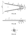
FIG. 2A is a top plan view, FIG. 2B is a side elevation view, and FIG. 2C is a cross-sectional view of a disk drive suspension design with a lift tab having a gimbal limiter positioned proximal to the dimple.
FIG. 3A is a top plan view, FIG. 3B is a side elevation view, FIG. 3D is a cross-sectional end view of a disk drive suspension design with a lift tab having a gimbal limiter positioned longitudinally even with the dimple; FIG. 3C is a top plan view of a load beam attachment component.
FIG. 4A is a top plan view, FIG. 4B is a side elevation view, and FIG. 4D is a cross-sectional end view of another embodiment of a disk drive head suspension design with a lift tab having a gimbal limiter positioned longitudinally even with the dimple; FIG. 4C is a top plan view of a load beam attachment component.
FIG. 5A is a top plan view, FIG. 5B is a side elevation view, and FIG. 5C is a cross-sectional end view of a disk drive suspension design with a lift tab having a gimbal limiter positioned distal to the dimple.
FIG. 6A is a top plan view, FIG. 6B is a side elevation view, and FIG. 6C is a cross-sectional end view of another embodiment of a disk drive suspension design with a lift tab having a gimbal limiter positioned distal to the dimple.
FIG. 7A is a top plan view, FIG. 7B is a side elevation view, and FIG. 7C is a cross-sectional end view of yet another embodiment of a disk drive suspension design with a lift tab having a gimbal limiter positioned distal to the dimple.
DETAILED DESCRIPTION OF THE INVENTION
The present disclosure provides head suspensions for precisely supporting a slider on a load beam with a gimbal and a gimbal limiter. The designs are particularly suited for thin load beams (e.g., less than 0.05 mm in thickness) that have a lift tab at the distal end of the beam.
In the following description, reference is made to the accompanying drawing that forms a part hereof and in which are shown by way of illustration various specific embodiments. The description provides additional specific embodiments. It is to be understood that other embodiments are contemplated and may be made without departing from the scope or spirit of the present invention. The following Detailed Description, therefore, is not to be taken in a limiting sense. While the present invention is not so limited, an appreciation of various aspects of the invention will be gained through a discussion of the examples provided below.
Unless otherwise indicated, all numbers expressing feature sizes, amounts, and physical properties are to be understood as being modified by the term “about.” Accordingly, unless indicated to the contrary, the numerical parameters set forth are approximations that can vary depending upon the desired properties sought to be obtained by those skilled in the art utilizing the teachings disclosed herein.
As used herein, the singular forms “a”, “an”, and “the” encompass embodiments having plural referents, unless the content clearly dictates otherwise. As used in this specification and the appended claims, the term “or” is generally employed in its sense including “and/or” unless the content clearly dictates otherwise.
Returning to head suspensions, to prevent damage during handling and in-drive shock events, gimbal limiters are incorporated into gimbal designs to limit the extent of their motion. FIGS. 1A, 1B, and 1C illustrate a gimbal limiter design for a suspension without a lift tab, and FIGS. 2A, 2B and 2C illustrate a gimbal limiter design for a suspension with a lift tab.
Gimbal limiters are more effective if they can be positioned longitudinally along the load beam at the dimple location, or distal to the dimple location. A gimbal limiter is more effective when it is at or near the trailing edge side of the slider, rather than at the leading edge side of the slider. This positioning of the gimbal limiter is readily achievable for suspension designs without lift tabs as shown in FIGS. 1A, 1B and 1C.
FIGS. 1A, 1B and 1C illustrate a suspension design that has a load beam 10 with a proximal end 10A and a distal end 10B. Load beam 10 has an elongate central planar surface 11 bounded by rails 12 that extend from the proximal end 10A toward distal end 10B of load beam 10; rails 12 are illustrated as on the top surface of load beam 10, although in other embodiments rails 12 may be present on the bottom surface of load beam 10. Load beam 10 is generally formed from stainless steel. Rails 12 provide lateral and bending stiffening and increase torsion resistance to load beam 10; in some embodiments, rails 12 provide a mechanism for supporting electrical features (not shown). Rails 12 are typically present on ‘thin’ load beams 10 having a thickness of planar surface 11 that is less than 0.05 mm; load beams made from a thicker material may not include rails, as the material itself provides sufficient stiffness to beam 10. Rails 12 are often formed by folding or bending the material (e.g., stainless steel) that forms central planar surface 11.
Connected to load beam 10 is a gimbal flexure or spring 14, or merely gimbal 14, which flexibly supports a slider 100. Gimbal 14 is positioned on the bottom of load beam 10, between load beam 10 and the disk. Slider 100 has a leading edge 100A on the proximal side of slider 100 and a trailing edge 100B on the distal side of slider 100, and includes an upper surface facing gimbal 14 and load beam 10 and a lower air bearing surface (ABS) 102.
In the illustrated embodiment, gimbal 14 extends the length of load beam 10 from proximal end 10A to distal end 10B, although in other embodiments gimbal 14 may not extend back to proximal end 10A. At distal end 10B, gimbal 14 includes flexure arms or struts 15 supported by and extending both laterally and longitudinally in spaced cantilevered relation from load beam 10. Distal end 10B of load beam 10 is operably coupled to gimbal struts 15. Struts 15 are spaced relative to the width of slider 100 a certain distance from its centerline, and struts 15 are sized to provide desired roll characteristics. It is generally known that if gimbal struts 15 are spaced too far apart, roll stiffness increases and if spaced too close, roll stiffness is too low. If the width of gimbal struts 15 is too thick, roll and pitch stiffness increases and if too thin, the gimbal lacks sufficient mechanical robustness. The overall design of gimbal struts 15, and of gimbal 14 itself, can be adjusted from that disclosed herein and still remain within the scope of the invention described herein.
In this embodiment of the suspension, central surface 11 includes a load-bearing dimple 16 at distal end 10B extending toward slider 100. In alternate embodiments, dimple 16 may be present on gimbal 14. Dimple 16 applies a load force between load beam 10 and the upper surface of slider 100 and defines a laterally extending pivot axis about which slider 100 can pitch, and a longitudinally extending pivot axis about which slider 100 can roll, to follow the topography of the disk surface. Dimple 16 is generally at the center of slider 100, both laterally and longitudinally, for flight stability of slider 100 during operation.
During operation of the disk drive, it is important to maintain a stable fly height for slider 100 close to the disk surface and that slider 100 be able to pitch and roll to follow the topography of the disk surface. Thus, gimbal 14 is designed to support slider 100 relative to load beam 10 to allow sufficient pitch and roll of slider 100 about dimple 16 during operation. If the pitch and roll stiffness of gimbal 14 is too low, gimbal 14 will lack sufficient mechanical robustness, whereas if gimbal 14 is too stiff in the pitch and roll axes, then slider 100 will not be able to follow the topography of the disk surface.
During a shock event, such as during shipping or if the disk drive is dropped, slider 100 can pull gimbal 14 away from load beam 10 in the absence of some deflection limiting mechanism. The stress from the shock event could be high enough to distort gimbal 14 and result in changes to the pitch and roll static angle of gimbal 14. A deflection limiting mechanism prevents this from happening by ensuring that the deflection is not too large to cause the stress on gimbal 14 to reach the yield point.
The suspension of FIGS. 1A, 1B and 1C includes a limiter 18 that sets a maximum distance slider 100 can move away from dimple 16 and load beam 10. Best seen in FIGS. 1B and 1C, in this embodiment, limiter 18 includes two arms or tab members that extend from gimbal 14 at slider 100 and bend over load beam 10, thus limiting the distance of travel of slider 100 from dimple 16. Limiter 18 is essentially longitudinally aligned with dimple 16, or in other words, is essentially even with dimple 16.
This design of limiter 18 is easy to implement with gimbal 14 and load beam 10. However, for suspension designs with a lift tab (which is often included at distal end 10B of load beam 10 for reasons described below), the limiter and gimbal design of FIGS. 1A, 1B, and 1C is not suitable because the load beam rails extend all the way to the end of the load beam and often to the lift tab, thus interfering with the limiter. The rails do not provide sufficient clearance for the gimbal features to wrap around load beam 10 at dimple 16.
Unless indicated otherwise, the various features of subsequent embodiments described herein are consistent with and the same as the similar various features of the embodiment described above of FIGS. 1A, 1B and 1C.
FIGS. 2A, 2B and 2C illustrate a suspension design that has a load beam 20 with a proximal end 20A and a distal end 20B with a lift tab 23 at distal end 20B. Similar to the previous embodiment, load beam 20 has an elongate central planar surface 21 bounded by rails 22 that extend from the proximal end 20A to distal end 20B. The suspension of this embodiment includes lift tab 23, which is configured to engage a ramp (not shown) when the disk drive is in a non-operating state and during deceleration of the disk during power-down operations. In order to provide sufficient stiffness to load beam 20, rails 22 extend to lift tab 23.
Connected to load beam 20 is a gimbal 24, which flexibly supports slider 100. In the illustrated embodiment, gimbal 24 extends the length of load beam 20 from proximal end 20A to distal end 20B. Gimbal 24, in this embodiment, extends short of the end of lift tab 23.
A dimple 26 formed in load beam 20 applies a load force between load beam 20 and the upper surface of slider 100 and defines a laterally extending pivot axis about which slider 100 can pitch, and a longitudinally extending pivot axis about which slider 100 can roll. In alternate embodiments, dimple 26 may be present on gimbal 24. Dimple 26 is at the center portion of slider 100 for flight stability of slider 100. As seen in FIGS. 2A and 2B, rails 22 extend distal of dimple 26.
A limiter 28 sets a maximum distance slider 100 can move away from dimple 26 and load beam 20. In this embodiment, limiter 28 includes a single center tab member that extends from gimbal 24, through load beam 20 to engage load beam 20, thus limiting the distance of travel of slider 100 from dimple 26. The limiter 28 of FIGS. 2A, 2B and 2C, however, is not a preferred embodiment, because limiter 28 is positioned at leading edge 100A of slider 100, or on the proximal side of dimple 26.
The following embodiments describe various embodiments of load beams with a lift tab and stiffening rails having gimbal limiters that have the limiter located at the dimple or trailing edge side of the dimple. Again, unless indicated otherwise, the various features of the subsequent embodiments described herein are consistent with and the same as the similar various features of the embodiments described above. In each of the embodiments, the suspension includes at least one tab member fixed to the load beam, and a gimbal limiter defined by the at least one tab member and a portion of the gimbal. Either the tab member or the gimbal is bent or folded to connect the tab member to the gimbal and form the gimbal limiter. In at least some embodiments, the gimbal limiter is present outside of the footprint of the slider, i.e., either laterally spaced out from the slider or distal to the slider (at or distal to the trailing edge of the slider)).
FIGS. 3A, 3B, 3C, 3D and 4A, 4B, 4C, 4D illustrate embodiments where two tab members extend out laterally from the load beam and longitudinally aligned with the dimple. In one embodiment, a portion of the gimbal is folded to engage the tab members and in the other embodiment, a portion of the tab members is folded to engage the gimbal.
Referring to FIGS. 3A, 3B, 3C and 3D, the suspension design has a load beam 30 with a proximal end 30A and a distal end 30B with a lift tab 33 at distal end 30B. Load beam 30 has an elongate central planar surface 31 bounded by continuous rails 32 that extend from the proximal end 30A to distal end 30B and to lift tab 33 in order to provide sufficient stiffness to load beam 30. Connected to load beam 30 is a gimbal 34, which flexibly supports slider 100. In the illustrated embodiment, gimbal 34 extends the length of load beam 30 from proximal end 30A to distal end 30B. Gimbal 34 extends short of the end of lift tab 33.
A dimple 36, positioned at the center of slider 100, applies a load force between load beam 30 and the upper surface of slider 100 and defines a laterally extending pivot axis about which slider 100 can pitch, and a longitudinally extending pivot axis about which slider 100 can roll. Best seen in FIG. 3B, rails 32 extend distal of dimple 36.
Fixed to load beam 30, between load beam 30 and gimbal 34, is at least one tab member 35, in this embodiment two tab members, a first tab member 35A and a second tab member 35B, which extend laterally out from load beam 30 in opposite directions. A portion of gimbal 34 is folded to engage tab members 35A, 35B, which are sufficiently long to extend past rails 32 and engage with gimbal 34, to form gimbal limiter 38 laterally outside of rails 32 and laterally outside of a footprint 105 of slider 100. In this embodiment, gimbal limiter 38 is composed of two structures, one formed by each tab member 35A, 35B, and is longitudinally aligned with dimple 36.
In this embodiment, best seen in FIG. 3C, tab members 35A, 35B are present on a component 37 that is not integral with, but prior to being fixed to load beam 30, is a separate and discrete component. Depending on the specific design and manufacturing process of load beam 30 and gimbal 34, having a discrete component 37 may be preferred over having the component formed integral with gimbal 34 or load beam 30. A discrete component may be attached to load beam 30 and/or gimbal 34 by, e.g., soldering, welding, or adhesive. In the illustrated embodiment, component 37 includes an aperture 39 that allows dimple 36 to pass therethrough.
FIGS. 4A, 4B, 4C and 4D illustrate an embodiment similar to that of FIGS. 3A, 3B, 3C, 3D, where two tab members extend out laterally from the load beam to form a gimbal limiter that is longitudinally aligned with the dimple. Similar to the suspension of FIGS. 3A, 3B and 3D, the suspension design of FIGS. 4A, 4B and 4D has a load beam 40 with a proximal end 40A and a distal end 40B with a lift tab 43 at distal end 40B. Load beam 40 has an elongate central planar surface 41 bounded by continuous rails 42 to provide sufficient stiffness to load beam 40. Connected to load beam 40 is a gimbal 44, which extends the length of load beam 40 from proximal end 40A to distal end 40B yet extends short of the end of lift tab 43.
A dimple 46, positioned at the center of slider 100, applies a load force between load beam 40 and the upper surface of slider 100 and defines a laterally extending pivot axis about which slider 100 can pitch, and a longitudinally extending pivot axis about which slider 100 can roll. Best seen in FIG. 4B, rails 42 extend distal of dimple 46.
Fixed to load beam 40, between load beam 40 and gimbal 44, is at least one tab member 45, in this embodiment two tab members, a first tab member 45A and a second tab member 45B, which extend laterally out from load beam 40 in opposite directions past rails 42. In this embodiment, a portion of tab members 45A, 45B is folded to engage gimbal 44 to form gimbal limiter 48 laterally outside of rails 42 and laterally outside of footprint 105 of slider 100. In this embodiment, gimbal limiter 48 is composed of two structures, one formed by each tab member 45A, 45B, and is longitudinally aligned with dimple 46.
Similar to the previous embodiment, best seen in FIG. 4C, tab members 45A, 45B are present on a separate and discrete component 47. Depending on the specific design and manufacturing process of load beam 40 and gimbal 44, having a discrete component 47 may be preferred over having the component formed integral with gimbal 44 or load beam 40. Similar to the previous embodiment, component 47 includes an aperture 49 that allows dimple 46 to pass therethrough.
FIGS. 5A, 5B and 5C, 6A, 6B and 6C, and 7A, 7B and 7C illustrate embodiments where one tab member extends distally from the load beam distal to the dimple. In some embodiments, a portion of the gimbal is folded to engage the tab member and in other embodiments a portion of the tab member is folded to engage the gimbal. In all of these embodiments, the resulting gimbal limiter is positioned at the trailing edge side of the gimbal.
Referring to FIGS. 5A, 5B and 5C, the suspension design has a load beam 50 with a proximal end 50A and a distal end 50B with a lift tab 53 at distal end 50B. Load beam 50 has an elongate central planar surface 51 bounded by continuous rails 52 that extend from the proximal end 50A to distal end 50B and to lift tab 53 in order to provide sufficient stiffness to load beam 50. Connected to load beam 50 is a gimbal 54, which flexibly supports slider 100. In the illustrated embodiment, gimbal 54 extends the length of load beam 50 from proximal end 50A to distal end 50B yet extends short of the end of lift tab 53.
A dimple 56, positioned at the center of slider 100, defines a laterally extending pivot axis about which slider 100 can pitch, and a longitudinally extending pivot axis about which slider 100 can roll. Best seen in FIG. 5B, rails 52 extend distal of dimple 56.
Fixed to load beam 50 at distal end 50B is at least one tab member 55, which extends longitudinally, centrally and distally out from load beam 50. Tab member 55 is positioned between lift tab 53 and gimbal 54. A portion of gimbal 54, in this embodiment the distal-most portion of gimbal 54, is folded to engage tab member 55 to form gimbal limiter 58 on the trailing edge side of slider 100, and in this illustrated embodiment, distal to the trailing edge of slider 100 and distal to (i.e., outside of) footprint 105 of slider 100.
FIGS. 6A, 6B and 6C illustrate another embodiment having a tab member extending distally from the load beam and distal of the dimple, the tab member forming a gimbal limiter. The suspension design of FIGS. 6A, 6B and 6C has a load beam 60 with a proximal end 60A and a distal end 60B with a lift tab 63 at distal end 60B. Load beam 60 has an elongate central planar surface 61 bounded by continuous rails 62 that extend from the proximal end 60A to distal end 60B and to lift tab 63 in order to provide sufficient stiffness to load beam 60. Connected to load beam 60 is a gimbal 64, which flexibly supports slider 100.
A dimple 66, positioned at the center of slider 100, defines a laterally extending pivot axis about which slider 100 can pitch, and a longitudinally extending pivot axis about which slider 100 can roll. Best seen in FIG. 6B, rails 62 extend distal of dimple 66.
Fixed to load beam 60 at distal end 60B is at least one tab member 65, which extends longitudinally and centrally out from load beam 60. Tab member 65 is positioned between lift tab 63 and gimbal 64. A portion of tab member 65 is folded to engage gimbal 64 to form gimbal limiter 68 on the trailing edge side of slider 100, and in particular, distal to the trailing edge of slider 100 and distal to footprint 105 formed by slider 100. In this embodiment, tab member 65 is folded less than 90 degrees, e.g., about 60 degrees, to engage gimbal 64.
FIGS. 7A, 7B and 7C illustrate an embodiment similar to that of FIGS. 6A, 6B and 6C where a tab member extending distally from the load beam and distal of the dimple is bent to form a gimbal limiter. Similar to the suspension of FIGS. 6A, 6B and 6C, the suspension design of FIGS. 7A, 7B and 7C has a load beam 70 with a proximal end 70A and a distal end 70B with a lift tab 73 at distal end 70B. Load beam 70 has an elongate central planar surface 71 bounded by continuous rails 72 that extend from the proximal end 70A to distal end 70B and to lift tab 73 in order to provide sufficient stiffness to load beam 70. Connected to load beam 70 is a gimbal 74, which flexibly supports slider 100.
A dimple 76, positioned at the center of slider 100, defines a laterally extending pivot axis about which slider 100 can pitch, and a longitudinally extending pivot axis about which slider 100 can roll. Best seen in FIG. 7B, rails 72 extend distal of dimple 76.
Fixed to load beam 70 at distal end 70B is at least one tab member 75, which extends longitudinally and centrally out from load beam 70. Tab member 75 is positioned between lift tab 73 and gimbal 74. A portion of tab member 75 is folded down and back to engage gimbal 74 to form gimbal limiter 78 on the trailing edge side of slider 100 and in particular, distal to the trailing edge of slider 100 and distal to footprint 105 formed by slider 100. In this embodiment, tab member 75 is folded about 90 degrees twice, to form a return to gimbal 74.
Various embodiments of disk drive suspensions comprising a load beam with a lift tab and stiffening rails and having gimbal limiters located at the dimple or trailing edge side of the dimple have been described. In general, each of these embodiments has at least one tab member, extending either longitudinally or laterally from the load beam at or distal to the dimple, the tab member forming a gimbal limiter. In most embodiments, the gimbal limiter is symmetric along the longitudinal axis of the suspension. The illustrated embodiments can be separated into two general categories. The first has the tab member(s) extending laterally from the load beam directly at or distal to the dimple. The tab member(s) may be integrally formed on, in, or with the load beam or be present on a component separate from the load beam, the component being secured to the load beam in some manner (e.g., soldering, welding, or adhesive). As indicated above, however, in most embodiments the gimbal limiter is symmetric along the longitudinal axis, so that the same number of tab member(s) is present on each side of the load beam and in the same location. The second category has a tab member extending longitudinally from the load beam (in most embodiments, a centrally located tab member extending from the load beam), the tab member being distal to the dimple, and in some embodiments distal to the trailing edge of the slider. The longitudinal tab member may be integrally formed on, in, or with the load beam or be present on a component separate from the load beam. Both of the categories of tab members allow the gimbal limiter to be positioned in the desired location, which is at the dimple or on the trailing edge half of the slider without interrupting the continuous rails on the load beam.
Specifically, FIGS. 3A, 3B, 3C and 3D and FIGS. 4A, 4B, 4C and 4D are particular examples that utilize an additional component for the tab members to enable a limiter at the dimple location. The embodiment of FIGS. 3A, 3B, 3C and 3D has an additional component that is flat and a gimbal feature (e.g., upwardly extending posts or ears) that engages the tab members on this flat component. Alternatively, the embodiment of FIGS. 4A, 4B, 4C and 4D has an additional component with a formed tab feature (e.g., downwardly bent returns) that engage the gimbal with no additional feature required on the gimbal. The additional component may be any suitable material, e.g., plastic, metal, etc., although in some embodiments the same material is used for the component as for the load beam (e.g., stainless steel).
FIGS. 5A, 5B and 5C, FIGS. 6A, 6B and 6C, and FIGS. 7A, 7B and 7C are particular examples that utilize a center tab feature extending longitudinally from center of the load beam. All three of these embodiments have a gimbal limiter that engages the gimbal at the trailing edge side of the gimbal. The embodiment of FIGS. 5A, 5B and 5C maintains a flat center tab feature on the load beam, extending from the planar center portion of the load beam. For this embodiment, the gimbal has a feature that is formed upward (e.g., bent) to engage this flat center tab. The embodiment of FIGS. 6A, 6B and 6C has the center tab formed downward (e.g., bent) from the load beam center portion and is interleaved with an aperture in the gimbal. The embodiment of FIGS. 7A, 7B and 7C has a center tab that is formed (e.g., bent) around the gimbal to form a return.
As indicated above, ‘thin’ load beams, those with thicknesses of about 0.05 mm or less (e.g., 0.025-0.05 mm) utilize continuous rails along their lengths to provide sufficient torsional stability and stiffness to the load beam. In some embodiments load beams thicker than 0.05 mm may include side rails. In order to provide sufficient stiffness, the rails extend at least to the dimple, and in most embodiments, extend distal of the dimple. Preferably, the rails are continuous, void of any breaks along their length. As one particular example, a stainless steel load beam, about 0.03 mm thick, has side rails that extend about 0.25 mm above the planar surface of the load beam.
In most embodiments, the gimbal limiter, no matter which embodiment described or illustrated herein, allows no more than 0.1 mm travel of the gimbal and slider from the dimple, in some embodiments no more than 0.08 mm. The distance of travel allowed is usually at least 0.05 mm, which is generally sufficient to accommodate the pitching and rolling of the slider.
It is understood that numerous variations of gimbal limiters could be made while maintaining the overall inventive designs of this disclosure and remaining within the scope of the invention. Thus, various embodiments of the GIMBAL LIMITER FOR SUSPENSION WITH LIFT TAB are disclosed. The implementations described above and other implementations are within the scope of the following claims. One skilled in the art will appreciate that the present invention can be practiced with embodiments other than those disclosed. The disclosed embodiments are presented for purposes of illustration and not limitation, and the present invention is limited only by the claims that follow.

Claims (14)

What is claimed is:
1. A head suspension for a disk drive comprising:
load beam having a proximal end and a distal end and comprising a distal lift tab, the load beam supporting a gimbal including a portion for supporting a slider;
a dimple positioned proximal to the lift tab, the dimple being operatively positioned on one of the load beam and the gimbal for providing a pitch axis and a roll axis for the slider;
continuous rails on the load beam extending along the load beam toward the distal end, the rails extending to at least the dimple;
an attachment component including a first portion and a pair of tab members that extend from the first portion, the first portion of the attachment component being fixed to a surface of the load beam facing the gimbal so that the pair of tab members also extend laterally from the load beam, the tab members aligned with or distal to the dimple; and
a gimbal limiter formed by engagement of the tab members and the gimbal, the gimbal limiter aligned with or distal to the dimple.
2. The suspension of claim 1 wherein the tab members are bent to engage the gimbal.
3. The suspension of claim 1 wherein the gimbal is bent to engage the tab members.
4. The suspension of claim 1, wherein the attachment component is fixedly attached to the gimbal.
5. The suspension of claim 1, wherein the attachment component is fixedly attached to the load beam.
6. The suspension of claim 5 wherein the attachment component is welded to the load beam.
7. The suspension of claim 1 wherein the load beam is less than 0.05 mm thick.
8. A head suspension for a disk drive comprising:
load beam having a proximal end and a distal end and comprising a distal lift tab, the load beam supporting a gimbal including a portion for supporting a slider;
a dimple positioned proximal to the lift tab, the dimple providing a pitch axis and a roll axis for the slider;
continuous rails on the load beam extending along the load beam toward the distal end, the rails extending to at least the dimple;
an attachment component including a first portion with an aperture and a plurality of tab members that extend from the first portion, the first portion of the attachment component being fixed to a surface of the load beam facing the gimbal with the dimple positioned within the aperture so that plural tab members also extend laterally in relation to the load beam, the tab members aligned with or distal to the dimple; and
a gimbal limiter formed by engagement of the tab members and the gimbal, the gimbal limiter aligned with or distal to the dimple.
9. The suspension of claim 8 wherein the two tab members extend symmetrically about a longitudinal axis of the load beam.
10. The suspension of claim 8 wherein the attachment component is fixedly attached to the gimbal.
11. The suspension of claim 8 wherein the attachment component is fixedly attached to the load beam.
12. The suspension of claim 11 wherein the attachment component is welded to the load beam.
13. The suspension of claim 8 wherein the tab members are bent to engage the gimbal.
14. The suspension of claim 8 wherein the gimbal is bent to engage the tab members.
US13/951,570 2011-07-20 2013-07-26 Gimbal limiter for suspension with lift tab Active US8837090B2 (en)

Priority Applications (1)

Application Number Priority Date Filing Date Title
US13/951,570 US8837090B2 (en) 2011-07-20 2013-07-26 Gimbal limiter for suspension with lift tab

Applications Claiming Priority (2)

Application Number Priority Date Filing Date Title
US13/186,947 US20130021698A1 (en) 2011-07-20 2011-07-20 Gimbal limiter for suspension with lift tab
US13/951,570 US8837090B2 (en) 2011-07-20 2013-07-26 Gimbal limiter for suspension with lift tab

Related Parent Applications (1)

Application Number Title Priority Date Filing Date
US13/186,947 Division US20130021698A1 (en) 2011-07-20 2011-07-20 Gimbal limiter for suspension with lift tab

Publications (2)

Publication Number Publication Date
US20130321957A1 US20130321957A1 (en) 2013-12-05
US8837090B2 true US8837090B2 (en) 2014-09-16

Family

ID=47534423

Family Applications (2)

Application Number Title Priority Date Filing Date
US13/186,947 Abandoned US20130021698A1 (en) 2011-07-20 2011-07-20 Gimbal limiter for suspension with lift tab
US13/951,570 Active US8837090B2 (en) 2011-07-20 2013-07-26 Gimbal limiter for suspension with lift tab

Family Applications Before (1)

Application Number Title Priority Date Filing Date
US13/186,947 Abandoned US20130021698A1 (en) 2011-07-20 2011-07-20 Gimbal limiter for suspension with lift tab

Country Status (3)

Country Link
US (2) US20130021698A1 (en)
JP (1) JP2013025861A (en)
CN (1) CN102890937B (en)

Cited By (3)

* Cited by examiner, † Cited by third party
Publication number Priority date Publication date Assignee Title
US11176961B2 (en) * 2020-03-04 2021-11-16 Kabushiki Kaisha Toshiba Suspension assembly and disk device
US20230020335A1 (en) * 2021-07-19 2023-01-19 Magnecomp Corporation Load Beam Including Slit Feature
US11591932B2 (en) 2019-08-08 2023-02-28 General Electric Company Shape memory alloy reinforced casing

Families Citing this family (14)

* Cited by examiner, † Cited by third party
Publication number Priority date Publication date Assignee Title
US8885299B1 (en) 2010-05-24 2014-11-11 Hutchinson Technology Incorporated Low resistance ground joints for dual stage actuation disk drive suspensions
JP6356682B2 (en) 2012-10-10 2018-07-11 ハッチンソン テクノロジー インコーポレイテッドHutchinson Technology Incorporated Suspension with two-stage operation structure
US8891206B2 (en) 2012-12-17 2014-11-18 Hutchinson Technology Incorporated Co-located gimbal-based dual stage actuation disk drive suspensions with motor stiffener
US8817424B1 (en) * 2013-03-12 2014-08-26 Seagate Technology Llc Arm assembly with lift tab
US8896969B1 (en) 2013-05-23 2014-11-25 Hutchinson Technology Incorporated Two-motor co-located gimbal-based dual stage actuation disk drive suspensions with motor stiffeners
US8717712B1 (en) 2013-07-15 2014-05-06 Hutchinson Technology Incorporated Disk drive suspension assembly having a partially flangeless load point dimple
US20150064672A1 (en) * 2013-09-05 2015-03-05 Matthew Bars Systems and methods for treatment of substance addiction
US8896970B1 (en) 2013-12-31 2014-11-25 Hutchinson Technology Incorporated Balanced co-located gimbal-based dual stage actuation disk drive suspensions
US9070392B1 (en) 2014-12-16 2015-06-30 Hutchinson Technology Incorporated Piezoelectric disk drive suspension motors having plated stiffeners
US9318136B1 (en) 2014-12-22 2016-04-19 Hutchinson Technology Incorporated Multilayer disk drive motors having out-of-plane bending
US9296188B1 (en) 2015-02-17 2016-03-29 Hutchinson Technology Incorporated Partial curing of a microactuator mounting adhesive in a disk drive suspension
WO2016164484A1 (en) * 2015-04-07 2016-10-13 Carrot Sense, Inc. Systems and methods for quantification of, and prediction of smoking behavior
WO2017003782A1 (en) 2015-06-30 2017-01-05 Hutchinson Technology Incorporated Disk drive head suspension structures having improved gold-dielectric joint reliability
US9646638B1 (en) 2016-05-12 2017-05-09 Hutchinson Technology Incorporated Co-located gimbal-based DSA disk drive suspension with traces routed around slider pad

Citations (40)

* Cited by examiner, † Cited by third party
Publication number Priority date Publication date Assignee Title
US4724500A (en) * 1986-08-14 1988-02-09 Tandon Corporation Mechanism for preventing shock damage to head slider assemblies and disks in rigid disk drive
US5333085A (en) 1990-11-06 1994-07-26 Seagate Technology, Inc. Read/write gimbal with limited range of motion
US5771136A (en) 1996-05-23 1998-06-23 Hutchinson Technology Incorporated Suspension assembly for mounting a head slider having a flexure with a shock limiter
US5815349A (en) * 1995-09-21 1998-09-29 International Business Machines Corporation Suspension with wire protection which does not impact slider movements
US5877920A (en) * 1996-07-10 1999-03-02 Seagate Technology, Inc. Head suspension assembly with displacement limiter
US5930079A (en) 1996-08-21 1999-07-27 Magnecomp Corp. Suspension having limited travel flexure for improved loadability
US6069773A (en) * 1995-12-01 2000-05-30 International Business Machines Corporation Shock protected high stack density suspension system
US6088201A (en) 1997-03-21 2000-07-11 Alps Electric Co., Ltd. Magnetic head device
US6181525B1 (en) 1998-09-23 2001-01-30 Read-Rite Corporation Read/write head with a limited range of motion relative to a load beam
US6191915B1 (en) 1997-11-06 2001-02-20 Nhk Spring Co., Ltd. Suspension for disc drive that is capable of restraining excessive inclination of a head or occurrence of dimple separation when it is shocked, without enhancing the stiffness of a flexure
US6233121B1 (en) 1999-04-09 2001-05-15 International Business Machines Corporation Magnetic disk drive suspension pitch motion limiter
US6243235B1 (en) 1999-04-16 2001-06-05 International Business Machines Corporation Transducer suspension system with limiter
US6388843B1 (en) 1999-01-04 2002-05-14 Nhk Spring Co., Ltd. Suspension for disc drive
US20020075602A1 (en) * 2000-12-15 2002-06-20 Mangold Markus E. Head gimbal assembly flexure arm displacement limiter
US6417996B1 (en) 1997-09-22 2002-07-09 Seagate Technology Llc Gimbal for a head of a disc drive with vertical limiter
US6424498B1 (en) * 1999-12-03 2002-07-23 Seagate Technology Llc Shock resistant suspension limiter for a disc drive
US6445546B1 (en) 1999-03-24 2002-09-03 Magnecomp Corporation Snap-in assembly of suspension limiter having both high shock and load/unload cycle capability
US6538850B1 (en) 1999-10-06 2003-03-25 Read-Rite Corporation Low profile head gimbal assembly with shock limiting and load/unload capability and method of manufacture thereof
US6587309B2 (en) 2000-10-30 2003-07-01 Nhk Spring Co., Ltd. Suspension for disc drive
US6587311B1 (en) * 1999-12-13 2003-07-01 Fujitsu Limited Magnetic storage device having a head suspension
US6611402B1 (en) 1999-06-09 2003-08-26 Seagate Technology Llc Pitch-adjustable head suspension with end lift tab for dynamic load/unload
US6747849B1 (en) 2000-03-21 2004-06-08 Hitachi Global Storage Technologies Netherlands B.V. High performance suspension with reduced flow-induced vibration
US6801400B2 (en) 2002-01-24 2004-10-05 Hitachi Global Storage Technologies, The Netherlands B.V. Motion limiter for disk drive integrated gimbal suspension
US20050174696A1 (en) 2004-02-10 2005-08-11 Samsung Electronics Co., Ltd. Suspension assembly having flexure limiter and actuator of a hard disk drive using the same
US6995953B2 (en) 2002-10-09 2006-02-07 Seagate Technology Llc Head gimbal assembly high performance shock limiter
US7085104B1 (en) 1999-10-06 2006-08-01 Western Digital (Fremont), Inc. Low profile head gimbal assembly with shock limiting and load/unload capability
US7130157B2 (en) 2002-08-14 2006-10-31 Seagate Technology Llc Head suspension having a displacement limiter
US7236330B2 (en) * 2004-02-11 2007-06-26 Hitachi Global Storage Technologies Netherlands B.V. Disk head stability system
US20070230058A1 (en) 2006-04-03 2007-10-04 Hitachi Global Storage Technologies B.V. Assembly having slider and suspension, and disk drive unit
US7330338B1 (en) 2004-05-05 2008-02-12 Hutchinson Technology Incorporated Method for adjusting pitch and roll in a head suspension
US7369366B2 (en) 2003-08-25 2008-05-06 Samsung Electronics Co., Ltd. Suspension assembly of actuator for disk drive with portion of load beam inclined lengthwise between limiter and leading end
US20090009911A1 (en) 2007-07-06 2009-01-08 Sae Magnetics (H.K.) Ltd. Suspension With Locally Strengthened Gimbal
US7489478B2 (en) 2004-08-10 2009-02-10 Hitachi Global Storage Technologies Netherlands B.V. Magnetic disk drive head suspension having a lift tab which engages a limiter
US7535678B2 (en) 2006-01-10 2009-05-19 Hitachi Global Storage Technologies Netherlands B.V. Method and system for utilizing flexible members in a head gimbal assembly to reduce impact of operational disturbances of slider flying height
US20090154022A1 (en) * 2007-12-18 2009-06-18 Nhk Spring Co., Ltd. Disk drive suspension
US7583474B2 (en) 2004-02-18 2009-09-01 Hitachi Global Storage Technologies Netherlands B.V. Suspension and limiter mechanism for a data storage device
US7602585B2 (en) 2004-01-19 2009-10-13 Samsung Electronics Co., Ltd. Actuator for a disk drive having a suspension assembly including a flexure of a monolithic structure and a limiter
US7719797B1 (en) 2005-08-08 2010-05-18 Magnecomp Corporation Multi-step shock limiter for head gimbal assembly
US7839604B1 (en) 2005-02-03 2010-11-23 Seagate Technology Llc Disk drive suspension assembly with integrated trailing edge shock protection for use with micro-actuator type head-gimbal assembly
US8107198B1 (en) 2008-05-28 2012-01-31 Magnecomp Corporation Pitch moment-balanced gimbal for a disk drive suspension

Family Cites Families (2)

* Cited by examiner, † Cited by third party
Publication number Priority date Publication date Assignee Title
JP4335886B2 (en) * 2006-04-20 2009-09-30 日本発條株式会社 Disk drive suspension
US20070268629A1 (en) * 2006-05-18 2007-11-22 Seagate Technology Llc Suspension Buckling Limiter

Patent Citations (42)

* Cited by examiner, † Cited by third party
Publication number Priority date Publication date Assignee Title
US4724500A (en) * 1986-08-14 1988-02-09 Tandon Corporation Mechanism for preventing shock damage to head slider assemblies and disks in rigid disk drive
US5333085A (en) 1990-11-06 1994-07-26 Seagate Technology, Inc. Read/write gimbal with limited range of motion
US5815349A (en) * 1995-09-21 1998-09-29 International Business Machines Corporation Suspension with wire protection which does not impact slider movements
US6069773A (en) * 1995-12-01 2000-05-30 International Business Machines Corporation Shock protected high stack density suspension system
US5771136A (en) 1996-05-23 1998-06-23 Hutchinson Technology Incorporated Suspension assembly for mounting a head slider having a flexure with a shock limiter
US5877920A (en) * 1996-07-10 1999-03-02 Seagate Technology, Inc. Head suspension assembly with displacement limiter
US5930079A (en) 1996-08-21 1999-07-27 Magnecomp Corp. Suspension having limited travel flexure for improved loadability
US6088201A (en) 1997-03-21 2000-07-11 Alps Electric Co., Ltd. Magnetic head device
US6417996B1 (en) 1997-09-22 2002-07-09 Seagate Technology Llc Gimbal for a head of a disc drive with vertical limiter
US6191915B1 (en) 1997-11-06 2001-02-20 Nhk Spring Co., Ltd. Suspension for disc drive that is capable of restraining excessive inclination of a head or occurrence of dimple separation when it is shocked, without enhancing the stiffness of a flexure
US6181525B1 (en) 1998-09-23 2001-01-30 Read-Rite Corporation Read/write head with a limited range of motion relative to a load beam
US6388843B1 (en) 1999-01-04 2002-05-14 Nhk Spring Co., Ltd. Suspension for disc drive
US6445546B1 (en) 1999-03-24 2002-09-03 Magnecomp Corporation Snap-in assembly of suspension limiter having both high shock and load/unload cycle capability
US6233121B1 (en) 1999-04-09 2001-05-15 International Business Machines Corporation Magnetic disk drive suspension pitch motion limiter
US6243235B1 (en) 1999-04-16 2001-06-05 International Business Machines Corporation Transducer suspension system with limiter
US6611402B1 (en) 1999-06-09 2003-08-26 Seagate Technology Llc Pitch-adjustable head suspension with end lift tab for dynamic load/unload
US7010847B1 (en) 1999-10-06 2006-03-14 Western Digital (Fremont), Inc. Method of manufacturing a head gimbal assembly with substantially orthogonal tab, side beam and base
US6538850B1 (en) 1999-10-06 2003-03-25 Read-Rite Corporation Low profile head gimbal assembly with shock limiting and load/unload capability and method of manufacture thereof
US7085104B1 (en) 1999-10-06 2006-08-01 Western Digital (Fremont), Inc. Low profile head gimbal assembly with shock limiting and load/unload capability
US6424498B1 (en) * 1999-12-03 2002-07-23 Seagate Technology Llc Shock resistant suspension limiter for a disc drive
US6587311B1 (en) * 1999-12-13 2003-07-01 Fujitsu Limited Magnetic storage device having a head suspension
US6747849B1 (en) 2000-03-21 2004-06-08 Hitachi Global Storage Technologies Netherlands B.V. High performance suspension with reduced flow-induced vibration
US6587309B2 (en) 2000-10-30 2003-07-01 Nhk Spring Co., Ltd. Suspension for disc drive
US20020075602A1 (en) * 2000-12-15 2002-06-20 Mangold Markus E. Head gimbal assembly flexure arm displacement limiter
US6801400B2 (en) 2002-01-24 2004-10-05 Hitachi Global Storage Technologies, The Netherlands B.V. Motion limiter for disk drive integrated gimbal suspension
US7130157B2 (en) 2002-08-14 2006-10-31 Seagate Technology Llc Head suspension having a displacement limiter
US6995953B2 (en) 2002-10-09 2006-02-07 Seagate Technology Llc Head gimbal assembly high performance shock limiter
US7369366B2 (en) 2003-08-25 2008-05-06 Samsung Electronics Co., Ltd. Suspension assembly of actuator for disk drive with portion of load beam inclined lengthwise between limiter and leading end
US7602585B2 (en) 2004-01-19 2009-10-13 Samsung Electronics Co., Ltd. Actuator for a disk drive having a suspension assembly including a flexure of a monolithic structure and a limiter
US20050174696A1 (en) 2004-02-10 2005-08-11 Samsung Electronics Co., Ltd. Suspension assembly having flexure limiter and actuator of a hard disk drive using the same
US7236330B2 (en) * 2004-02-11 2007-06-26 Hitachi Global Storage Technologies Netherlands B.V. Disk head stability system
US7583474B2 (en) 2004-02-18 2009-09-01 Hitachi Global Storage Technologies Netherlands B.V. Suspension and limiter mechanism for a data storage device
US7330338B1 (en) 2004-05-05 2008-02-12 Hutchinson Technology Incorporated Method for adjusting pitch and roll in a head suspension
US7489478B2 (en) 2004-08-10 2009-02-10 Hitachi Global Storage Technologies Netherlands B.V. Magnetic disk drive head suspension having a lift tab which engages a limiter
US7839604B1 (en) 2005-02-03 2010-11-23 Seagate Technology Llc Disk drive suspension assembly with integrated trailing edge shock protection for use with micro-actuator type head-gimbal assembly
US7719797B1 (en) 2005-08-08 2010-05-18 Magnecomp Corporation Multi-step shock limiter for head gimbal assembly
US7535678B2 (en) 2006-01-10 2009-05-19 Hitachi Global Storage Technologies Netherlands B.V. Method and system for utilizing flexible members in a head gimbal assembly to reduce impact of operational disturbances of slider flying height
US20070230058A1 (en) 2006-04-03 2007-10-04 Hitachi Global Storage Technologies B.V. Assembly having slider and suspension, and disk drive unit
US20090009911A1 (en) 2007-07-06 2009-01-08 Sae Magnetics (H.K.) Ltd. Suspension With Locally Strengthened Gimbal
US20090154022A1 (en) * 2007-12-18 2009-06-18 Nhk Spring Co., Ltd. Disk drive suspension
US8116039B2 (en) * 2007-12-18 2012-02-14 Nhk Spring Co., Ltd. Disk drive suspension
US8107198B1 (en) 2008-05-28 2012-01-31 Magnecomp Corporation Pitch moment-balanced gimbal for a disk drive suspension

Cited By (4)

* Cited by examiner, † Cited by third party
Publication number Priority date Publication date Assignee Title
US11591932B2 (en) 2019-08-08 2023-02-28 General Electric Company Shape memory alloy reinforced casing
US11176961B2 (en) * 2020-03-04 2021-11-16 Kabushiki Kaisha Toshiba Suspension assembly and disk device
US20230020335A1 (en) * 2021-07-19 2023-01-19 Magnecomp Corporation Load Beam Including Slit Feature
US11862209B2 (en) * 2021-07-19 2024-01-02 Magnecomp Corporation Load beam including slit feature

Also Published As

Publication number Publication date
CN102890937A (en) 2013-01-23
JP2013025861A (en) 2013-02-04
US20130021698A1 (en) 2013-01-24
CN102890937B (en) 2016-02-10
US20130321957A1 (en) 2013-12-05

Similar Documents

Publication Publication Date Title
US8837090B2 (en) Gimbal limiter for suspension with lift tab
US6538850B1 (en) Low profile head gimbal assembly with shock limiting and load/unload capability and method of manufacture thereof
US7085104B1 (en) Low profile head gimbal assembly with shock limiting and load/unload capability
EP0442225B1 (en) Head/gimbal assembly having low stiffness cross band flexure
KR100282028B1 (en) Suspension system for disk drive
EP0644530B1 (en) Transducer suspension system
US5973882A (en) Moment-flex head suspension
US5850319A (en) Head suspension for use with a dynamic storage drive having an optimized top profile defined by curved side edges
US6741424B1 (en) Head suspension with rail and stiffener combination
US6504684B1 (en) Head suspension with integral shock limiter
US6778362B1 (en) Hinged load beam with torsional spring
US6801400B2 (en) Motion limiter for disk drive integrated gimbal suspension
JP2008243360A (en) Head gimbal assembly, disk drive, and method for reducing slider roll torque
US6351350B1 (en) Shock limiter system for a head suspension
US5734525A (en) Head suspension with torsion spring region
US5381288A (en) Center moment suspension assembly
US11900972B2 (en) Non-operational shock mitigation for a suspension device
US6417996B1 (en) Gimbal for a head of a disc drive with vertical limiter
JP2009295261A (en) Magnetic head suspension
US20110090600A1 (en) Suspension, head gimbal assembly and disk drive unit with the same
JP2006313603A (en) Head suspension
US7885040B2 (en) Suspension with locally strengthened gimbal
US9214176B1 (en) PZT limiter for a micro dual stage actuated suspension
US5877923A (en) Head suspension assembly
US7667930B1 (en) Disk drive suspension and flexure with doubly and differentially deflected frame

Legal Events

Date Code Title Description
AS Assignment

Owner name: SEAGATE TECHNOLOGY LLC, CALIFORNIA

Free format text: ASSIGNMENT OF ASSIGNORS INTEREST;ASSIGNORS:GREMINGER, MICHAEL ALLEN;ZAMBRI, RAZMAN;BRANDTS, JACKSON WILLIAM;SIGNING DATES FROM 20110711 TO 20110713;REEL/FRAME:031063/0760

FEPP Fee payment procedure

Free format text: PAYOR NUMBER ASSIGNED (ORIGINAL EVENT CODE: ASPN); ENTITY STATUS OF PATENT OWNER: LARGE ENTITY

STCF Information on status: patent grant

Free format text: PATENTED CASE

MAFP Maintenance fee payment

Free format text: PAYMENT OF MAINTENANCE FEE, 4TH YEAR, LARGE ENTITY (ORIGINAL EVENT CODE: M1551)

Year of fee payment: 4

MAFP Maintenance fee payment

Free format text: PAYMENT OF MAINTENANCE FEE, 8TH YEAR, LARGE ENTITY (ORIGINAL EVENT CODE: M1552); ENTITY STATUS OF PATENT OWNER: LARGE ENTITY

Year of fee payment: 8