US8836424B2 - Amplifier circuit, method and mobile communication device - Google Patents
Amplifier circuit, method and mobile communication device Download PDFInfo
- Publication number
- US8836424B2 US8836424B2 US13/549,756 US201213549756A US8836424B2 US 8836424 B2 US8836424 B2 US 8836424B2 US 201213549756 A US201213549756 A US 201213549756A US 8836424 B2 US8836424 B2 US 8836424B2
- Authority
- US
- United States
- Prior art keywords
- amplifier
- gain
- amplifying
- value
- amplifying units
- Prior art date
- Legal status (The legal status is an assumption and is not a legal conclusion. Google has not performed a legal analysis and makes no representation as to the accuracy of the status listed.)
- Active, expires
Links
- 238000010295 mobile communication Methods 0.000 title claims description 20
- 238000000034 method Methods 0.000 title description 44
- 230000007613 environmental effect Effects 0.000 claims description 11
- 230000003213 activating effect Effects 0.000 claims description 7
- 238000010586 diagram Methods 0.000 description 23
- 230000008569 process Effects 0.000 description 11
- 238000004590 computer program Methods 0.000 description 10
- 230000009897 systematic effect Effects 0.000 description 9
- 238000006243 chemical reaction Methods 0.000 description 7
- 238000012886 linear function Methods 0.000 description 5
- 238000005259 measurement Methods 0.000 description 3
- 230000003321 amplification Effects 0.000 description 2
- 230000008901 benefit Effects 0.000 description 2
- 230000008859 change Effects 0.000 description 2
- 238000004891 communication Methods 0.000 description 2
- 238000012937 correction Methods 0.000 description 2
- 230000001419 dependent effect Effects 0.000 description 2
- 238000013461 design Methods 0.000 description 2
- 230000006870 function Effects 0.000 description 2
- 238000003199 nucleic acid amplification method Methods 0.000 description 2
- 238000012545 processing Methods 0.000 description 2
- 241001025261 Neoraja caerulea Species 0.000 description 1
- 238000013459 approach Methods 0.000 description 1
- 238000004422 calculation algorithm Methods 0.000 description 1
- 238000004364 calculation method Methods 0.000 description 1
- 230000007246 mechanism Effects 0.000 description 1
- 238000012986 modification Methods 0.000 description 1
- 230000004048 modification Effects 0.000 description 1
- 238000004088 simulation Methods 0.000 description 1
- 238000012546 transfer Methods 0.000 description 1
Images


Classifications
-
- H—ELECTRICITY
- H03—ELECTRONIC CIRCUITRY
- H03F—AMPLIFIERS
- H03F1/00—Details of amplifiers with only discharge tubes, only semiconductor devices or only unspecified devices as amplifying elements
- H03F1/02—Modifications of amplifiers to raise the efficiency, e.g. gliding Class A stages, use of an auxiliary oscillation
- H03F1/0205—Modifications of amplifiers to raise the efficiency, e.g. gliding Class A stages, use of an auxiliary oscillation in transistor amplifiers
- H03F1/0277—Selecting one or more amplifiers from a plurality of amplifiers
-
- H—ELECTRICITY
- H03—ELECTRONIC CIRCUITRY
- H03F—AMPLIFIERS
- H03F3/00—Amplifiers with only discharge tubes or only semiconductor devices as amplifying elements
- H03F3/189—High-frequency amplifiers, e.g. radio frequency amplifiers
- H03F3/19—High-frequency amplifiers, e.g. radio frequency amplifiers with semiconductor devices only
- H03F3/195—High-frequency amplifiers, e.g. radio frequency amplifiers with semiconductor devices only in integrated circuits
-
- H—ELECTRICITY
- H03—ELECTRONIC CIRCUITRY
- H03F—AMPLIFIERS
- H03F3/00—Amplifiers with only discharge tubes or only semiconductor devices as amplifying elements
- H03F3/20—Power amplifiers, e.g. Class B amplifiers, Class C amplifiers
- H03F3/21—Power amplifiers, e.g. Class B amplifiers, Class C amplifiers with semiconductor devices only
- H03F3/211—Power amplifiers, e.g. Class B amplifiers, Class C amplifiers with semiconductor devices only using a combination of several amplifiers
-
- H—ELECTRICITY
- H03—ELECTRONIC CIRCUITRY
- H03F—AMPLIFIERS
- H03F3/00—Amplifiers with only discharge tubes or only semiconductor devices as amplifying elements
- H03F3/20—Power amplifiers, e.g. Class B amplifiers, Class C amplifiers
- H03F3/24—Power amplifiers, e.g. Class B amplifiers, Class C amplifiers of transmitter output stages
- H03F3/245—Power amplifiers, e.g. Class B amplifiers, Class C amplifiers of transmitter output stages with semiconductor devices only
-
- H—ELECTRICITY
- H03—ELECTRONIC CIRCUITRY
- H03F—AMPLIFIERS
- H03F3/00—Amplifiers with only discharge tubes or only semiconductor devices as amplifying elements
- H03F3/72—Gated amplifiers, i.e. amplifiers which are rendered operative or inoperative by means of a control signal
-
- H—ELECTRICITY
- H03—ELECTRONIC CIRCUITRY
- H03G—CONTROL OF AMPLIFICATION
- H03G3/00—Gain control in amplifiers or frequency changers
- H03G3/20—Automatic control
- H03G3/30—Automatic control in amplifiers having semiconductor devices
- H03G3/3036—Automatic control in amplifiers having semiconductor devices in high-frequency amplifiers or in frequency-changers
- H03G3/3042—Automatic control in amplifiers having semiconductor devices in high-frequency amplifiers or in frequency-changers in modulators, frequency-changers, transmitters or power amplifiers
-
- H—ELECTRICITY
- H03—ELECTRONIC CIRCUITRY
- H03F—AMPLIFIERS
- H03F2200/00—Indexing scheme relating to amplifiers
- H03F2200/411—Indexing scheme relating to amplifiers the output amplifying stage of an amplifier comprising two power stages
-
- H—ELECTRICITY
- H03—ELECTRONIC CIRCUITRY
- H03F—AMPLIFIERS
- H03F2203/00—Indexing scheme relating to amplifiers with only discharge tubes or only semiconductor devices as amplifying elements covered by H03F3/00
- H03F2203/20—Indexing scheme relating to power amplifiers, e.g. Class B amplifiers, Class C amplifiers
- H03F2203/21—Indexing scheme relating to power amplifiers, e.g. Class B amplifiers, Class C amplifiers with semiconductor devices only
- H03F2203/211—Indexing scheme relating to power amplifiers, e.g. Class B amplifiers, Class C amplifiers with semiconductor devices only using a combination of several amplifiers
- H03F2203/21136—An input signal of a power amplifier being on/off switched
-
- H—ELECTRICITY
- H03—ELECTRONIC CIRCUITRY
- H03F—AMPLIFIERS
- H03F2203/00—Indexing scheme relating to amplifiers with only discharge tubes or only semiconductor devices as amplifying elements covered by H03F3/00
- H03F2203/20—Indexing scheme relating to power amplifiers, e.g. Class B amplifiers, Class C amplifiers
- H03F2203/21—Indexing scheme relating to power amplifiers, e.g. Class B amplifiers, Class C amplifiers with semiconductor devices only
- H03F2203/211—Indexing scheme relating to power amplifiers, e.g. Class B amplifiers, Class C amplifiers with semiconductor devices only using a combination of several amplifiers
- H03F2203/21142—Output signals of a plurality of power amplifiers are parallel combined to a common output
-
- H—ELECTRICITY
- H03—ELECTRONIC CIRCUITRY
- H03F—AMPLIFIERS
- H03F2203/00—Indexing scheme relating to amplifiers with only discharge tubes or only semiconductor devices as amplifying elements covered by H03F3/00
- H03F2203/72—Indexing scheme relating to gated amplifiers, i.e. amplifiers which are rendered operative or inoperative by means of a control signal
- H03F2203/7215—Indexing scheme relating to gated amplifiers, i.e. amplifiers which are rendered operative or inoperative by means of a control signal the gated amplifier being switched on or off by a switch at the input of the amplifier
-
- H—ELECTRICITY
- H03—ELECTRONIC CIRCUITRY
- H03F—AMPLIFIERS
- H03F2203/00—Indexing scheme relating to amplifiers with only discharge tubes or only semiconductor devices as amplifying elements covered by H03F3/00
- H03F2203/72—Indexing scheme relating to gated amplifiers, i.e. amplifiers which are rendered operative or inoperative by means of a control signal
- H03F2203/7236—Indexing scheme relating to gated amplifiers, i.e. amplifiers which are rendered operative or inoperative by means of a control signal the gated amplifier being switched on or off by putting into parallel or not, by choosing between amplifiers by (a ) switch(es)
Definitions
- the present invention relates to amplifier circuits and mobile communication devices. Furthermore the present invention relates to methods for amplifying a signal.
- the present invention relates to an amplifier circuit comprising a gain controller, a first amplifier, and a second amplifier which is coupled in series to the first amplifier and which comprises a plurality of amplifying units.
- the gain controller is configured to receive a desired gain value and provide, based on the received desired gain value, a gain adjust signal to the first amplifier. Furthermore, the gain controller is configured to activate, based on the received desired gain value, a certain combination of amplifying units of the plurality of amplifying units of the second amplifier, such that a combined gain of the first amplifier and the active amplifying units of the second amplifier corresponds to the received desired gain value.
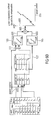
- FIG. 1 a shows a block schematic diagram of a mobile communication device
- FIG. 3 shows a block schematic diagram of an exemplary implementation of a power to gain mapper and a gain controller in an amplifier circuit
- FIG. 4 a shows a block schematic diagram of an exemplary implementation of a second amplifier of an amplifier circuit
- FIGS. 4 b to 4 d show different exemplary implementations of a power to gain mapper and a gain controller which may be implemented in the amplifier circuit comprising the second amplifier shown in FIG. 4 a;
- FIG. 5 a shows in a block schematic diagram of an exemplary implementation for a first amplifier and how it can be used in an amplifier circuit
- FIG. 5 b shows another exemplary implementation of the first amplifier
- FIG. 5 c shows in a block schematic diagram an exemplary implementation of a power to gain mapper and a gain controller which may be used in the amplifier circuit comprising the first amplifier shown in FIG. 5 a;
- FIG. 5 d shows in block schematic diagram an exemplary implementation of a power to gain mapper and a gain controller which may be used in the amplifier circuit comprising the first amplifier shown in FIG. 5 b;
- FIG. 6 a shows in a diagram a relationship between output power control and output power with discontinuities
- FIG. 6 d shows a further example of how the combined gain can be derived without discontinuity compensation
- FIG. 6 e shows an example of how the combined gain can be derived with a discontinuity compensation
- FIG. 7 shows an application example for an amplifier circuit
- FIG. 8 shows a flow diagram of a method for amplifying a signal.
- FIG. 1 a shows a block schematic diagram of an exemplary mobile communication device 800 .
- the mobile communication device 800 comprises a digital baseband processor 801 , an exemplary amplifier circuit 803 (e.g. one of the amplifier circuits described herein) and an antenna 211 .
- the amplifier circuit 803 is coupled between the digital baseband processor 801 and the antenna 211 .
- the digital baseband processor 801 provides a first amplifier input signal 113 to the amplifier circuit 803 and the antenna 211 is configured to relay an output signal 117 of the amplifier circuit 803 .
- the mobile communication device 800 may be a portable mobile communication device in one embodiment.
- the mobile communication device 800 can be configured to perform a voice and/or data communication (according to a mobile communication standard) with another (portable) mobile communication device and/or a mobile communication base station.
- a mobile communication device may be, for example, a mobile headset such as a mobile phone (cell phone), a so called smart phone, a tablet PC, a broadband modem, a notebook or a laptop, as well as a router, switch, repeater or a PC.
- a mobile communication device may be a mobile communication base station.
- the amplifier circuit 803 enables a power adjustment in the mobile communication device 800 with low calibration efforts, less points for calibration, an easy correction of temperature, an easy determination of power control values and a very linear function between the power control values and the achieved output power of the mobile communication device.
- the amplifier circuit 803 is presented as part of the mobile communication device 800 , this amplifier circuit may be also used in other circuits or devices. In the following, different examples of such amplifier circuit will be described in more detail.
- FIG. 1 b shows an exemplary amplifier circuit 100 .
- the amplifier circuit 100 comprises a gain controller 101 , a first amplifier 103 and a second amplifier 105 .
- the second amplifier 105 is coupled in series to the first amplifier 103 .
- the second amplifier 105 comprises a plurality of amplifying units 107 a , 107 b.
- the gain controller 101 is configured to receive a desired gain value 109 and provide, based on the desired gain value 109 , a gain adjust signal 111 to the first amplifier 103 . Furthermore, the gain controller 101 is configured to activate, based on the received desired gain value 109 , a certain combination of amplifying units 107 a , 107 b of the plurality of amplifying units 107 a , 107 b of the second amplifier 105 , such that a combined gain of the first amplifier 103 and the active amplifying units 107 a , 107 b of the second amplifier 105 corresponds to (e.g. equals) the received desired gain value 109 .
- An improved gain adjustment of an amplifier circuit can be achieved, when a first amplifier is used in conjunction with a second amplifier, wherein the second amplifier comprises a plurality of amplifying stages which can be activated and deactivated by a gain controller based on a desired gain value.
- the second amplifier comprises a plurality of amplifying stages which can be activated and deactivated by a gain controller based on a desired gain value.
- the amplifying circuit 100 provides a continuous gain adjustment over a large range of gain values.
- the amplifying circuit 100 comprises the following additional features.
- the first amplifier 103 is configured to receive a first amplifier input signal 113 (which is also an input signal 103 of the amplifier circuit 100 ). Furthermore, the first amplifier 103 is configured to apply a first gain to the received first amplifier input signal 113 based on the gain adjust signal 111 . Furthermore, the first amplifier 103 is configured to provide a second amplifier input signal 115 to the second amplifier 105 . The second amplifier input signal 115 is an amplified version of the first amplifier input signal 113 .
- the first amplifier 103 may be a digital amplifier (such as a digital multiplier). Hence, the first amplifier input signal 113 may be a digital signal.
- the second amplifier 105 may be an analog amplifier configured to receive the second amplifier input signal 115 as an analog signal.
- the amplifying circuit 100 may comprise a digital-to-analog converter coupled between the first amplifier 103 and the second amplifier 105 which is configured to convert the second amplifier input signal 115 from the digital domain (as provided by the first amplifier 103 ) to the analog domain (as received by the second amplifier 105 ).
- the second amplifier 105 is configured to apply a second gain to the received second amplifier input signal 105 to derive an amplifier circuit output signal 117 (also designated as output signal 117 ).
- the second gain applied by the second amplifier 105 is a sum of the gains applied by the activated amplification units 107 a , 107 b of the second amplifier 105 .
- the combined gain of the amplifier circuit 100 (which could also be designated as the overall gain of the amplifier circuit 100 ) is the gain difference between the first amplifier input signal 113 and the amplifier circuit output signal 117 .
- each of the amplifying units 107 a , 107 b is a discrete amplifying unit, which means that in an activated state this amplifying unit applies a gain to a signal received at its input and that this amplifying unit omits applying the gain to the signal received at its input in the deactivated state.
- a gain applied by an amplifying unit 107 a , 107 b may be non-adjustable (i.e., fixed).
- different amplifying units 107 a , 107 b can comprise different gains.
- the gains applied by the amplifying units 107 a , 107 b can be binary scaled.
- the second amplifier 105 can comprise a plurality of amplifying stages, which are coupled in series between the input 119 and the output 121 of the second amplifier 105 .
- Each of these amplifying stages can comprise a plurality of amplifying units 107 a , 107 b which are coupled in parallel between an input and an output of the respective amplifying stage.
- the second amplifier 105 comprises, in one embodiment, four amplifying units 107 a - 107 d , nevertheless, as already pointed out, the number of amplifying units in the second amplifier 105 can vary.
- each value of the switch code 123 can correspond to a predetermined range of (succeeding) values of the desired gain value 109 .
- the output 121 of the second amplifier 105 is coupled to an antenna 211 (which may be external to the RF receiver 200 ).
- Each of the amplifying units 107 a - 107 d is configured to apply in an activated state a corresponding gain to the analog signal 115 b (the second amplifier input signal 115 in the analog domain) received at the input 119 of the second amplifier 105 . Furthermore, a second amplifier gain applied by the second amplifier 105 to the analog signal 115 b is a sum of the corresponding gains of the activated amplifying units 107 a - 107 d of the second amplifier (wherein the combination of activated amplifying units 107 a - 107 d is determined by the switch code 123 ).
- Each of the amplifying stages 107 a - 107 b is a discrete unit (discrete in the meaning of can be activated independently of the other amplifying units 107 a - 107 d ). Each of these discrete stages is configured to apply, in an activated state, a corresponding gain to the to the analog signal 115 b received at the input 119 of the second amplifier 105 and omit, in a deactivated state, applying the corresponding gain to the to the analog signal 115 b.
- the deactivated amplifying unit 107 a - 107 d is bypassed.
- each amplifying unit 107 a - 107 d may be non-adjustable or fixed. Furthermore, all of the amplifying units 107 a - 107 d may be configured to apply the same corresponding gain to the analog signal 115 b.
- the amplifying units 107 a - 107 d may differ in the corresponding gain they apply to the analog signal 115 b .
- the corresponding gains of the amplifying units 107 a - 107 d may be binary scaled with respect to one another.
- the first amplifier 103 is a digital amplifier 103 which is configured to amplify the first amplifier input signal 113 based on the gain adjust signal 111 .
- FIG. 2 b shows a block schematic diagram of another exemplary amplifier circuit 250 .
- the amplifier circuit 250 differs from the amplifier circuit 200 shown in FIG. 2 a in that an exemplary implementation of the first amplifier 103 is shown.
- the amplifier 103 comprises a digital multiplier 251 which is configured to multiply the first amplifier input signal 113 (also designated as digital data signal 113 , transmit signal 113 or input signal 113 ) with the gain adjust signal 111 to derive the digital signal 115 a (the second amplifier input signal 115 in the digital domain).
- a digital multiplier 251 which is configured to multiply the first amplifier input signal 113 (also designated as digital data signal 113 , transmit signal 113 or input signal 113 ) with the gain adjust signal 111 to derive the digital signal 115 a (the second amplifier input signal 115 in the digital domain).
- the relationship between the gain adjust signal 111 and the resulting power of the second amplifier input signal 115 is a linear relationship. Such a linear relationship can easily be calculated using the digital multiplier 103 .
- the gain controller 101 comprises a discontinuity compensation lookup table 252 in which for each desired gain value (and therefore for each desired output power of the output signal 117 ) a discontinuity compensation value 253 (also designated as error) is provided.
- the gain controller 101 is configured to derive the gain adjust signal 111 furthermore based on the discontinuity compensation value 253 provided in the discontinuity compensation lookup table 252 for the desired gain value 119 or desired output power of the output signal 117 .
- discontinuity compensation discontinuities in the output power versus power control, characteristics can be eliminated such that the resulting relationship between the power control value 205 indicating the desired output power of the output signal 117 and the resulting output power of the output signal 117 is a linear relationship (without discontinuities).
- FIGS. 6 a - 6 e More details on the discontinuity compensation are also shown in FIGS. 6 a - 6 e.
- FIG. 3 shows a block schematic diagram of an exemplary implementation for the power to gain mapper 203 and the gain controller 101 how they can be used in an exemplary amplifier circuit.
- the power to gain mapper 203 receives the power control value 205 indicating the desired output power of the output signal 117 and derives, based on the power control value 205 , the desired gain value 109 .
- the power to gain mapper 203 comprises an amplifier circuit specific calibration pair of a reference gain value (TX_Gain_REF) and a resulting reference output power (P_REF) of the amplifying circuit in which the power to gain mapper 203 is used (for example of the amplifying circuit 200 , 250 ).
- the power to gain mapper 203 is configured to derive the desired gain value 109 further based on this calibration pair.
- the resulting reference output power at the amplifying circuit is measured in a calibration process of the amplifying circuit once and stored in the power to gain mapper 203 .
- the meaning of amplifier circuit specific is that different amplifier circuits can comprise different resulting reference output powers for the same reference gain value (e.g. resulting from process variations).
- the discontinuity compensation is optional.
- the gain controller 101 is configured to perform an optional logarithmic to linear conversion to derive the gain adjust signal 111 in the linear domain. Due to the fact that the first amplifier 103 (which is a linear amplifier) can be implemented as a multiplier, the controller 101 is configured to convert the gain adjust signal 111 from dB to linear (or in other words from the logarithmic domain to the digital domain). This dB to linear conversion can be performed using tables (e.g. lookup tables) or using an algorithm.
- a flexible, reprogrammable strategy is used which is implemented with tables (e.g. the lookup table 207 and the discontinuity compensation lookup table 252 ). It should be pointed out that for the lookup table 207 no measurement results are necessary, as it is sufficient to just define for which desired gain value 109 which value of the switch code 123 is to be provided.
- the different formulas for deriving the desired gain value 109 and the gain adjust signal 111 may be implemented in hardware or firmware. It is to be pointed out that the discontinuity compensation applied by the gain controller 101 using the discontinuity compensation lookup table 252 is optional and is used for compensating for inaccurate discrete gain steps of the second amplifier 105 . These inaccurate gain steps are measured (calibrated) and stored in the discontinuity compensation lookup table 252 before a use of the gain controller 101 . As an example, the discontinuity compensation lookup table 252 may be an amplifier specific discontinuity compensation lookup table 252 , such as the calibration pair for determining the desired gain value 109 .
- the gain controller 101 is configured to derive the gain adjust signal 111 based on the difference between the desired gain value 109 and the sum of the gains of the activated amplifying units 107 a - 107 d (indicated by Gain_Switch) and furthermore based on the discontinuity compensation value 253 provided in the discontinuity compensation lookup table 252 for the desired gain value 109 .
- FIG. 4 a shows a block schematic diagram of an exemplary implementation of the second amplifier 105 .
- the second amplifier 105 comprises a plurality of amplifying stages 401 a , 401 b , 401 c .
- the plurality of amplifying stages 401 a , 401 b , 401 c are coupled in series between the input 119 and the output 121 of the second amplifier 105 .
- each of the amplifying stages 401 a - 401 c comprise a plurality of amplifying units which are coupled in parallel between an input and an output of the respective amplifying stage 401 a - 401 c .
- a first amplifying stage 401 a comprises a first amplifying unit 401 a - 1 and a second amplifying unit 401 a - 2 which are coupled in parallel between an input 403 and an output 405 of the first amplifying stage 401 a .
- a second amplifying stage 401 b comprises four amplifying units 401 b - 1 to 401 b - 4 which are coupled between an input 407 and an output 409 of the second amplifying stage 401 b .
- a third amplifying stage 401 c comprises four amplifying units 401 c - 1 to 401 c - 4 which are coupled in parallel between an input 411 and an output 413 of the third amplifying stage 401 c .
- Each of the amplifying units 401 a - 1 to 401 c - 4 can be activated independently of the other amplifying units 401 a - 1 to 401 c - 4 . Furthermore, each of the amplifying stages 401 a - 401 c is configured to receive a respective switch code 123 a - 123 c from the gain controller 101 .
- the amplifier 105 comprises a plurality of amplifying stages 401 a - 401 c .
- An input of the first amplifying stage 401 a is coupled to the input 119 of the second amplifier 105 .
- the output 405 of the first amplifying stage 401 a is coupled to the input 407 of the second amplifying stage 401 b.
- the output 409 of the second amplifying stage 401 b is coupled to the input 411 of the third amplifying stage 401 c .
- the output 413 of the third amplifying stage 401 c is coupled to the output 121 of the second amplifier 105 .
- FIG. 4 b shows in a block schematic diagram an implementation for the power to gain mapper 203 and the gain controller 101 how they can be used in an amplifying circuit together with the second amplifier 105 shown in FIG. 4 a.
- the gain controller 101 shown in FIG. 4 b differs from the gain controller 101 shown in FIG. 3 in that it further comprises a logic circuit 415 which is configured to derive based on the switch code 123 for the second amplifier 105 , a first switch code 123 a for the first amplifying stage 401 a , a second switch code 123 b for the second amplifying stage 101 b and a third switch code for the third amplifying stage 401 c of the second amplifier 105 .
- the logic circuit 415 it is configured to split the switch code 123 for the second amplifier 105 into the plurality of switch codes 123 a - 123 c for the different amplifying stages 401 a - 401 c of the second amplifier 105 .
- the switch codes 123 a - 123 c may be designated also as digital codes for the amplifying stages 401 a - 401 c of the second amplifier 105 .
- FIG. 4 c shows in a block schematic diagram another exemplary implementation for the gain controller 101 which is configured to provide the plurality of switch codes 123 a - 123 c .
- the lookup table 407 comprises for each desired gain value 109 a respective value for each switch code 123 a - 123 c for each amplifying stage 401 a - 401 c of the second amplifier 105 .
- each value of the switch code 123 a - 123 c may correspond to a predetermined range of values of the desired gain value 109 .
- the look up table 207 it is not necessary to have for every possible value of the desired gain 109 a table entry. It is sufficient to have table entries provided for values of the desired gain 109 for which a state of the second amplifier 105 (i.e. the number of activated amplifying units) is to be changed and therefore for which at least one value of one of the switch codes 123 a - 123 c is to be changed.
- FIG. 4 d shows in a block schematic diagram a further exemplary implementation for the power to gain mapper 203 and the gain controller 101 .
- the implementation shown in FIG. 4 d differs from the implementations shown in FIG. 4 c in that the power to gain mapper 203 is further configured to derive the desired gain value 109 based on environmental conditions of the amplifying circuit in which the power to gain mapper 203 is used.
- the power to gain mapper 203 derives the desired gain value 109 furthermore based one or more environmental condition(s) such as a power amplifier bias change, temperature of the amplifier circuit, frequency of the first amplifier input signal 113 and supply voltage (such as battery voltage).
- the power to gain mapper 203 can be configured to derive the desired gain value 109 based on at least one of these environmental conditions.
- the power to gain mapper 203 is configured to, based on the current environmental condition (e.g.
- a combination of the bias voltage of the amplifier circuit, the temperature of the amplifier circuit, the supply voltage of the amplifier circuit and the frequency of the first amplifier input signal 113 ) choose a compensation value out of a plurality of (stored) compensation values and derive the desired gain value 109 further based on this chosen compensation value.
- the compensation value COMP may be a sum of different compensation values, wherein each of the different compensation values corresponds to one of the environmental conditions.
- the compensation values or the different compensation values for the different environmental conditions can be derived, for example, based on one or more lookup table(s) or based on formulas.
- Each compensation value can be derived in conjunction with the amplifier specific calibration pair, as the determination of the calibration pair happens at a certain biasing point (for a given power amplifier setting, temperature, battery voltage and frequency) of the amplifier circuit, which enables that the variations of these parameters can be regarded in the determination of the desired gain value 109 .
- FIGS. 5 a and 5 b show exemplary implementations for the first amplifier 103 , which are based on the assumption that a transmit signal to be amplified by the amplifying circuit is a complex signal which can be represented by a real part and an imaginary part or by a magnitude part (or amplitude part) and a phase part.
- FIG. 5 a shows how the first amplifier 103 can be implemented if the transmit signal is represented by a real part and an imaginary part. In this case the first amplifier input signal 113 equals the transmit signal.
- FIG. 5 b shows how the first amplifier 103 can be implemented if the transmit signal is represented by a magnitude part and a phase part. In this case the first amplifier input signal 113 equals the magnitude part of the transmit signal, as only this part needs to be amplified.
- FIG. 5 a shows an implementation in which the first amplifier 103 is configured to apply a first gain to a real part 113 - 1 of the first amplifier input signal 113 and a second gain to an imaginary part 113 - 2 of the first amplifier input signal 113 .
- the first amplifier 103 shown in FIG. 5 a comprises a first multiplier 501 a and a second multiplier 501 b .
- the first multiplier 501 a and the second multiplier 501 b are digital multipliers.
- the first multiplier 501 a is configured to receive a first gain adjust signal 503 a (also designated as Gain_Amp1_RE) and multiply the first gain adjust signal 503 a with the real part 113 - 1 of the first amplifier input signal 113 derive a first multiplier output signal 505 a .
- the second multiplier 501 b is configured to receive a second gain adjust signal 503 b (also designated as Gain_Amp1_IM) and multiply the second gain adjust signal 503 b with the imaginary part 113 - 2 of the first amplifier input signal 113 to derive a second multiplier output signal 505 b.
- the first multiplier output signal 505 a forms a real part of the digital signal 115 a (the second amplifier input signal 115 in the digital domain) and the second multiplier output signal 505 b forms an imaginary part of the digital signal 115 a (the second amplifier input signal 115 in the digital domain).
- the first analog output signal 509 a forms a real part of the analog signal 115 b (the second amplifier input signal 115 in the analog domain) and the second analog output signal 509 b forms an imaginary part of the analog signal 115 b (the second amplifier input signal 115 b in the analog domain).
- the first amplifier 103 as shown in FIG. 5 a is configured to adjust the first gain for the real part 113 - 1 of the first amplifier input signal 113 independently of the second gain applied to the imaginary part 113 - 2 of the first amplifier input signal 113 .
- each of the multipliers 501 a , 501 b may be implemented as a 12 ⁇ 12 bit multiplier (the gain adjust signals 503 a , 503 b may have 12 bits and the real part 113 - 1 and the imaginary part 113 - 2 of the first amplifier input signal 113 may have 12 bits). Furthermore, the first amplifier input signal 113 is provided to the first amplifier 103 as a first stream of digital data comprising the real part 113 - 1 of the first amplifier input signal 113 and a second stream of digital data comprising the imaginary part 113 - 2 of the first amplifier input signal 113 .
- FIG. 5 b shows another exemplary implementation of the first amplifier 103 , in which a single multiplier is sufficient.
- this implementation of the first amplifier 103 can be used in an amplifier circuit which is configured to receive the amplifier input signal 113 as a magnitude part of a transmit signal.
- the first amplifier 103 comprises a multiplier 251 which is configured to multiply the first amplifier input signal 113 by the gain adjust signal 111 to derive the digital signal 115 a (the second amplifier input signal 115 a in the digital domain).
- the digital-to-analog converter 201 is shown which is configured to convert the second amplifier input signal 115 from the digital domain to the analog domain.
- the amplifier input signal 113 may be a transmit signal which is represented by the real part 113 - 1 and the imaginary part 113 - 2 or may be a magnitude part of the transmit signal.
- the gain adjust signal 111 , 503 a , 503 b therefore can adjust the level of the magnitude of the transmit signal or the levels of the real part 113 - 1 and the imaginary part 113 - 2 of the transmit signal.
- FIG. 5 c shows in a block schematic diagram an exemplary implementation of the power to gain mapper 203 and the gain controller 101 which can be used in conjunction with the first amplifier 103 as shown in FIG. 5 a .
- the gain controller 101 is configured to provide the first gain adjust signal 503 a for adjusting the first gain applied to the real part 113 - 1 of the first amplifier input signal 113 and provide the second gain adjust signal 503 b for adjusting the second gain applied to the imaginary part 113 - 2 of the first amplifier input signal 113 .
- FIG. 5 c shows in a block schematic diagram an exemplary implementation of the power to gain mapper 203 and the gain controller 101 which can be used in conjunction with the first amplifier 103 as shown in FIG. 5 a .
- the gain controller 101 is configured to provide the first gain adjust signal 503 a for adjusting the first gain applied to the real part 113 - 1 of the first amplifier input signal 113 and provide the second gain adjust signal 503 b for adjusting the second gain applied to the imaginary part 113
- the gain controller 101 is configured to derive based on the desired gain value 109 a base gain adjust signal 511 and scale the base gain adjust signal 511 by a first scaling factor 513 a (or designated as Gain_Max_RE) to derive the first gain adjust signal 503 a . Furthermore, the gain controller 101 is configured to scale the base gain adjust signal 511 by a second scaling factor 513 b (also designated as Gain_Max_IM) to derive the second gain adjust signal 503 b.
- a first scaling factor 513 a or designated as Gain_Max_RE
- the gain controller 101 is configured to scale the base gain adjust signal 511 by a second scaling factor 513 b (also designated as Gain_Max_IM) to derive the second gain adjust signal 503 b.
- the first scaling factor 513 a can be different from the second scaling factor 513 b .
- the first gain adjust signal 503 a can differ from the second gain adjust signal 503 b.
- the gain controller 101 is configured to vary the first gain adjust signal 503 a and the second gain adjust signal 503 b individually.
- FIG. 5 c shows the implementation of the gain controller 101 in which the base gain adjust signal 511 is scaled after the dB to linear conversion before the level of the transmit signal is adjusted in the first amplifier 103 .
- FIG. 5 c shows an exemplary implementation of the gain controller 101 in which the gain controller 101 is further configured to compensate for systematic errors.
- the gain controller 101 comprises a systematic error lookup table 515 in which for each desired gain value 109 a respective systematic error compensation value (error_Gswitch_sys) is provided.
- the gain controller 101 is therefore configured to further derive the gain adjust signals 503 a , 503 b based on the systematic error compensation value for the desired gain value 109 .
- FIG. 5 c shows an implementation of the gain controller 101 in which systematic inaccuracies (which means same behavior for all amplifier circuits) are added in the formula for deriving the base gain adjust signal 511 .
- systematic errors can be stored once in the integrated circuit (e.g. in the systematic error lookup table 515 ) and don't need a calibration process.
- the calculation of the gain adjust signal 111 or the gain adjust signals 503 a , 503 b can be done very easy and the calibration efforts can be kept low.
- the implementation of the gain controllers can be done in hardware, firmware or in both.
- FIG. 5 d shows in a block schematic diagram another exemplary implementation for the power to gain mapper 203 and the gain controller 101 which differs from the implementation shown in FIG. 5 c in that the gain controller 101 is configured to provide the gain adjust signal 111 to the first amplifier 103 shown in FIG. 5 b .
- the gain controller 101 is configured to derive, based on the desired gain value 109 , the base gain adjust signal 511 and is configured to scale the base gain adjust signal 511 by a scaling factor 513 (also designated as Gain_Max) to derive the gain adjust signal 111 for the first amplifier 103 .
- a scaling factor 513 also designated as Gain_Max
- FIG. 6 a shows in a diagram a relationship between output power control and output power with discontinuities between the different linear segments.
- the length of the linear section respectively the number of discrete steps is dependent on the method of implementation (area, current).
- area, current area, current
- this discontinuity compensation can be performed in the gain controller 101 using the discontinuation compensation lookup table 252 to achieve a linear relationship between the output power control value 205 and the achieved output power of the output signal 117 .
- FIG. 6 c shows an exemplary implementation for the power to gain mapper 203 and the gain controller 101 using a table 607 containing all possible control settings with all parameters for adjusting the power in the linear region and with discrete power steps.
- the gain controller 101 can be configured to derive using the table 607 the gain adjust signal 111 for the first amplifier 103 to adjust a first gain 601 of the first amplifier 103 and the switch code 123 for the second amplifier 105 to adjust a second gain 603 of the second amplifier 105 .
- the first gain 601 and the second gain 603 together form a combined gain 605 of the complete amplifier circuit which comprises the first amplifier 103 and the second amplifier 105 .
- FIG. 6 d Another solution is shown in FIG. 6 d in which only those power control settings are used where power steps occur along with the discrete power steps themselves. Similar sections between the discrete power points can be achieved by means of digital hardware. As an example, the level of a signal can be scaled with a multiplier (e.g. with the multipliers 251 , 501 a , 501 b ) within digital signal processing. The linear functionality of the first amplifier 103 can easily be calculated. Such an implementation is shown in FIG. 6 d.
- FIG. 6 e shows another implementation in which inaccurate gain steps of the second amplifier 205 are compensated. These inaccurate gain steps can lead to discontinuities in the output power versus power control (value) characteristic.
- a calibration process can measure the steps and calculate the necessary shift values for all linear segments to end up with a very linear function of output power vs. power control value.
- the found shift values can be added to the linear power adjustment function (in the gain controller 101 as the discontinuity compensation values).
- the information of the shifts can be stored, for example, in the discontinuity compensation lookup table 252 .
- the gain controller 101 is configured to perform a discontinuity compensation of inaccurate gain steps of the second amplifier 105 based on the discontinuity compensation look up table 252 applied to the gain adjust signals 111 , 503 a , 503 b for the first amplifier 103 .
- the discontinuities can be considered within the implementation of the transmit device and no calibration process is required.
- FIG. 7 shows an application example for an operation of an exemplary amplifier circuit.
- a calibration of the amplifier circuit can be performed to determine the calibration pair as described in conjunction with FIG. 3 .
- the discontinuity compensation lookup table 252 then comprises for each desired gain value and therefore for each power control value a discontinuity compensation value.
- the discontinuity compensation value is derived such that no interpolation is necessary and it can be directly added in the linear function to derive the gain adjust signals 111 , 503 a , 503 b.
- PC equals the desired gain value 109
- PCref equals the reference gain value
- Psoll the desired output power indicated by the power control value 205
- Pref the reference output power of the amplifying circuit
- k is a proportionality constant.
- the actual gain value can be derived as 1975 and the desired gain value can be derived as 1991.
- Advantages of the power adjustment strategy shown in FIG. 7 are low calibration efforts, less points for calibration, an easy correction of temperature, an easy determination of the power control values (of the desired gain value) and a very linear function between the power control value 205 and the achieved output power of the amplifying circuit.
- a compensation of the environmental conditions can be performed (e.g. as described in conjunction with FIG. 4 d ) having additional compensation values for different environmental conditions (such as cold, ambient or warm for the environmental condition temperature).
- FIG. 3 the attention is also drawn to FIG. 3 in which the application example of FIG. 7 is also illustrated.
- the gain controller 101 chooses the value for the switch code 123 which corresponds to the next larger desired gain value in the lookup table 207 .
- the gain controller 101 chooses the value 30 for the switch code 123 corresponding to the desired gain value 2015.
- the gain controller 101 chooses based on the discontinuity compensation lookup table 252 the compensation value ⁇ 2 and derives based on the desired gain value 1991 and the discontinuity compensation value ⁇ 2 the gain adjust signal 111 .
- FIG. 8 shows a flow diagram of an exemplary method 900 for amplifying a signal.
- the method 900 comprises receiving a desired gain value at 901 .
- the method 900 comprises providing, based on the received desired gain value, a gain adjust signal to a first amplifier at 903 .
- the method 900 comprises activating, based on the received desired gain value, a certain combination of amplifying units of a plurality of amplifying units of a second amplifier, such that a combined gain of the first amplifier and the active amplifying units of the second amplifier corresponds to the received desired gain value at 915 .
- the method 900 may be supplemented by any of the features and functionalities described herein with respect to the apparatus, and may be implemented using the hardware components of the apparatus.
- aspects have been described in the context of an apparatus, it is clear that these aspects also represent a description of the corresponding method, where a block or device corresponds to a method step or a feature of a method step. Analogously, aspects described in the context of a method step also represent a description of a corresponding block or item or feature of a corresponding apparatus.
- Some or all of the method steps may be executed by (or using) a hardware apparatus, like for example, a microprocessor, a programmable computer or an electronic circuit. In some examples, some one or more of the most important method steps may be executed by such an apparatus.
- examples can be implemented in hardware or in software.
- the implementation can be performed using a digital storage medium, for example a floppy disk, a DVD, a Blue-Ray, a CD, a ROM, a PROM, an EPROM, an EEPROM or a FLASH memory, having electronically readable control signals stored thereon, which cooperate (or are capable of cooperating) with a programmable computer system such that the respective method is performed. Therefore, the digital storage medium may be computer readable.
- Some examples comprise a data carrier having electronically readable control signals, which are capable of cooperating with a programmable computer system, such that one of the methods described herein is performed.
- examples can be implemented as a computer program product with a program code, the program code being operative for performing one of the methods when the computer program product runs on a computer.
- the program code may for example be stored on a machine readable carrier.
- an implementation of the exemplary method is, therefore, a computer program having a program code for performing one of the methods described herein, when the computer program runs on a computer.
- a further implementation of the exemplary method is, therefore, a data carrier (or a digital storage medium, or a computer-readable medium) comprising, recorded thereon, the computer program for performing one of the methods described herein.
- the data carrier, the digital storage medium or the recorded medium are typically tangible and/or non-transitionary.
- a further implementation of the exemplary method is, therefore, a data stream or a sequence of signals representing the computer program for performing one of the methods described herein.
- the data stream or the sequence of signals may for example be configured to be transferred via a data communication connection, for example via the Internet.
- a further example comprises a processing means, for example a computer, or a programmable logic device, configured to or adapted to perform one of the methods described herein.
- a processing means for example a computer, or a programmable logic device, configured to or adapted to perform one of the methods described herein.
- a further example comprises a computer having installed thereon the computer program for performing one of the methods described herein.
- a further example comprises an apparatus or a system configured to transfer (for example, electronically or optically) a computer program for performing one of the methods described herein to a receiver.
- the receiver may, for example, be a computer, a mobile device, a memory device or the like.
- the apparatus or system may, for example, comprise a file server for transferring the computer program to the receiver.
- a programmable logic device for example a field programmable gate array
- a field programmable gate array may cooperate with a microprocessor in order to perform one of the methods described herein.
- the methods are preferably performed by any hardware apparatus.
Landscapes
- Engineering & Computer Science (AREA)
- Power Engineering (AREA)
- Microelectronics & Electronic Packaging (AREA)
- Amplifiers (AREA)
- Control Of Amplification And Gain Control (AREA)
Abstract
Description
TX_Gain=TX_Gain_REF+(P_TARGET−P_REF)*k,
wherein k could be, for example, 1, 2, 4, 8, . . . and wherein P_TARGET equals the desired output power of the
wherein
TX_Gain=TX_Gain_REF+(P_TARGET−P_REF)*k+COMP,
wherein COMP is the compensation value (e.g. power amplifier bias or power amplifier bias change, temperature, frequency, battery voltage or supply voltage).
wherein
PC=PCref+(Psoll−Pref)*k(e.g. k=16).
Claims (22)
Priority Applications (3)
| Application Number | Priority Date | Filing Date | Title |
|---|---|---|---|
| US13/549,756 US8836424B2 (en) | 2012-07-16 | 2012-07-16 | Amplifier circuit, method and mobile communication device |
| DE102013213833.4A DE102013213833A1 (en) | 2012-07-16 | 2013-07-15 | AMPLIFIER CIRCUIT, METHOD AND MOBILE COMMUNICATION DEVICE |
| CN201310410541.7A CN103580627B (en) | 2012-07-16 | 2013-07-16 | Amplifier circuit, method and mobile communications device |
Applications Claiming Priority (1)
| Application Number | Priority Date | Filing Date | Title |
|---|---|---|---|
| US13/549,756 US8836424B2 (en) | 2012-07-16 | 2012-07-16 | Amplifier circuit, method and mobile communication device |
Publications (2)
| Publication Number | Publication Date |
|---|---|
| US20140015604A1 US20140015604A1 (en) | 2014-01-16 |
| US8836424B2 true US8836424B2 (en) | 2014-09-16 |
Family
ID=49781692
Family Applications (1)
| Application Number | Title | Priority Date | Filing Date |
|---|---|---|---|
| US13/549,756 Active 2032-10-02 US8836424B2 (en) | 2012-07-16 | 2012-07-16 | Amplifier circuit, method and mobile communication device |
Country Status (3)
| Country | Link |
|---|---|
| US (1) | US8836424B2 (en) |
| CN (1) | CN103580627B (en) |
| DE (1) | DE102013213833A1 (en) |
Families Citing this family (9)
| Publication number | Priority date | Publication date | Assignee | Title |
|---|---|---|---|---|
| US9680434B2 (en) * | 2012-12-28 | 2017-06-13 | Mediatek, Inc. | Method and apparatus for calibrating an envelope tracking system |
| US20150333716A1 (en) * | 2014-05-13 | 2015-11-19 | Mediatek Inc. | Method and apparatus for performing signal amplifying with aid of switching control |
| KR102257344B1 (en) * | 2014-09-29 | 2021-05-27 | 삼성전자주식회사 | Apparatus and method for improving nonlinearity of power amplifier in wireless communication system |
| WO2016106162A1 (en) * | 2014-12-22 | 2016-06-30 | Microsemi Corporation | Log-linear power detector |
| FR3050025B1 (en) * | 2016-04-06 | 2018-07-20 | Thales | COMPACT RESONANT OPTICAL GYROMETER WITH THREE FREQUENCIES |
| US10116264B1 (en) * | 2017-05-31 | 2018-10-30 | Corning Optical Communications Wireless Ltd | Calibrating a power amplifier such as in a remote unit in a wireless distribution system (WDS) |
| CN107342739A (en) * | 2017-08-07 | 2017-11-10 | 上海立新液压有限公司 | A kind of dual-purpose amplifier of plug-type |
| US10663572B2 (en) * | 2018-06-19 | 2020-05-26 | Qualcomm Incorporated | Programmable multi-mode digital-to-analog converter (DAC) for wideband applications |
| CN114995568B (en) * | 2022-07-11 | 2023-11-17 | 苏州华芯半导体科技有限公司 | Current source with negative linear rate adjustment rate |
Citations (5)
| Publication number | Priority date | Publication date | Assignee | Title |
|---|---|---|---|---|
| US5136300A (en) * | 1991-06-13 | 1992-08-04 | Westinghouse Electric Corp. | Modular solid state radar transmitter |
| US20030132800A1 (en) * | 2000-02-08 | 2003-07-17 | Peter Kenington | Amplifier arrangement |
| US7091778B2 (en) * | 2003-09-19 | 2006-08-15 | M/A-Com, Inc. | Adaptive wideband digital amplifier for linearly modulated signal amplification and transmission |
| US20070229330A1 (en) | 2006-01-26 | 2007-10-04 | Srinivas Guda | Method and apparatus for achieving linear monotonic output power |
| US8004368B2 (en) * | 2008-09-15 | 2011-08-23 | Stmicroelectronics, S.R.L. | Radio frequency amplifier with digital amplitude modulation and method for controlling the delivering of power |
Family Cites Families (6)
| Publication number | Priority date | Publication date | Assignee | Title |
|---|---|---|---|---|
| US6950841B2 (en) * | 2001-07-16 | 2005-09-27 | Qualcomm Incorporated | Logarithmic lookup tables |
| KR100689400B1 (en) * | 2002-10-24 | 2007-03-08 | 삼성전자주식회사 | Automatic gain control apparatus and methods |
| AU2003283099B2 (en) * | 2002-11-04 | 2007-04-26 | Blackberry Limited | Method and apparatus for regulating the transmitted power in multi-rate wireless communication systems |
| JP2006526916A (en) * | 2003-05-09 | 2006-11-24 | コーニンクレッカ フィリップス エレクトロニクス エヌ ヴィ | Method and apparatus for setting transmission power of a mobile communication device |
| US7280812B2 (en) * | 2003-06-06 | 2007-10-09 | Interdigital Technology Corporation | Digital baseband receiver with DC discharge and gain control circuits |
| CN101873453B (en) * | 2010-06-23 | 2011-08-31 | 西安交通大学 | Automatic gain controller of composite video signal and control method thereof |
-
2012
- 2012-07-16 US US13/549,756 patent/US8836424B2/en active Active
-
2013
- 2013-07-15 DE DE102013213833.4A patent/DE102013213833A1/en active Pending
- 2013-07-16 CN CN201310410541.7A patent/CN103580627B/en active Active
Patent Citations (5)
| Publication number | Priority date | Publication date | Assignee | Title |
|---|---|---|---|---|
| US5136300A (en) * | 1991-06-13 | 1992-08-04 | Westinghouse Electric Corp. | Modular solid state radar transmitter |
| US20030132800A1 (en) * | 2000-02-08 | 2003-07-17 | Peter Kenington | Amplifier arrangement |
| US7091778B2 (en) * | 2003-09-19 | 2006-08-15 | M/A-Com, Inc. | Adaptive wideband digital amplifier for linearly modulated signal amplification and transmission |
| US20070229330A1 (en) | 2006-01-26 | 2007-10-04 | Srinivas Guda | Method and apparatus for achieving linear monotonic output power |
| US8004368B2 (en) * | 2008-09-15 | 2011-08-23 | Stmicroelectronics, S.R.L. | Radio frequency amplifier with digital amplitude modulation and method for controlling the delivering of power |
Also Published As
| Publication number | Publication date |
|---|---|
| US20140015604A1 (en) | 2014-01-16 |
| CN103580627B (en) | 2017-10-13 |
| CN103580627A (en) | 2014-02-12 |
| DE102013213833A1 (en) | 2014-01-16 |
Similar Documents
| Publication | Publication Date | Title |
|---|---|---|
| US8836424B2 (en) | Amplifier circuit, method and mobile communication device | |
| JP6084331B2 (en) | Apparatus and method for envelope tracking calibration | |
| US8183917B2 (en) | RF power amplifier circuit with mismatch tolerance | |
| US9088260B2 (en) | Operating parameter control for a power amplifier | |
| US6463264B1 (en) | Wireless communication apparatus and transmission power control method in wireless communication apparatus | |
| JP5527047B2 (en) | Amplification equipment | |
| TWI650935B (en) | System, circuit and method for dynamic error vector amplitude correction | |
| US8841967B2 (en) | Noise optimized envelope tracking system for power amplifiers | |
| JP2005184847A (en) | Digital detector which can be utilized in case that close loop gain control is offered in transmitter | |
| JP2003298429A (en) | Nonlinear distortion compensator | |
| US8742865B2 (en) | Polar modulation transmission circuit and polar modulation transmission method | |
| JP6720647B2 (en) | Power amplifier and control method thereof | |
| JP5069211B2 (en) | Temperature compensation circuit and temperature compensation method | |
| JP2010177771A (en) | High-frequency amplifying circuit | |
| US9281851B2 (en) | Power amplifier pre-distortion signal generator using an analog baseband envelope feedback loop | |
| JP4304296B2 (en) | Transmission power control circuit and wireless communication apparatus provided with transmission power control circuit | |
| US9100033B2 (en) | Systems and methods for using a digital power amplifier controller (DPAC) having foward-loop correction and feedback-loop correction | |
| JP2017028535A (en) | Transmission circuit and control method therefor | |
| JP2012195724A (en) | Radio transmitter, frequency characteristic correction method, and temperature characteristic correction method | |
| JP2012129806A (en) | High frequency amplifier |
Legal Events
| Date | Code | Title | Description |
|---|---|---|---|
| AS | Assignment |
Owner name: INTEL MOBILE COMMUNICATIONS GMBH, GERMANY Free format text: ASSIGNMENT OF ASSIGNORS INTEREST;ASSIGNORS:ESCHLBOECK, GERALD;MAYER, CHRISTIAN;SCHWARZ, ANDREAS;AND OTHERS;SIGNING DATES FROM 20120730 TO 20120913;REEL/FRAME:029029/0136 |
|
| FEPP | Fee payment procedure |
Free format text: PAYOR NUMBER ASSIGNED (ORIGINAL EVENT CODE: ASPN); ENTITY STATUS OF PATENT OWNER: LARGE ENTITY |
|
| STCF | Information on status: patent grant |
Free format text: PATENTED CASE |
|
| AS | Assignment |
Owner name: INTEL DEUTSCHLAND GMBH, GERMANY Free format text: CHANGE OF NAME;ASSIGNOR:INTEL MOBILE COMMUNICATIONS GMBH;REEL/FRAME:037057/0061 Effective date: 20150507 |
|
| MAFP | Maintenance fee payment |
Free format text: PAYMENT OF MAINTENANCE FEE, 4TH YEAR, LARGE ENTITY (ORIGINAL EVENT CODE: M1551) Year of fee payment: 4 |
|
| MAFP | Maintenance fee payment |
Free format text: PAYMENT OF MAINTENANCE FEE, 8TH YEAR, LARGE ENTITY (ORIGINAL EVENT CODE: M1552); ENTITY STATUS OF PATENT OWNER: LARGE ENTITY Year of fee payment: 8 |
|
| AS | Assignment |
Owner name: INTEL CORPORATION, CALIFORNIA Free format text: ASSIGNMENT OF ASSIGNORS INTEREST;ASSIGNOR:INTEL DEUTSCHLAND GMBH;REEL/FRAME:061356/0001 Effective date: 20220708 |