US8836226B2 - Leading-edge phase-cut bleeder control - Google Patents
Leading-edge phase-cut bleeder control Download PDFInfo
- Publication number
- US8836226B2 US8836226B2 US13/712,572 US201213712572A US8836226B2 US 8836226 B2 US8836226 B2 US 8836226B2 US 201213712572 A US201213712572 A US 201213712572A US 8836226 B2 US8836226 B2 US 8836226B2
- Authority
- US
- United States
- Prior art keywords
- current
- bleeder
- leading
- phase
- cut
- Prior art date
- Legal status (The legal status is an assumption and is not a legal conclusion. Google has not performed a legal analysis and makes no representation as to the accuracy of the status listed.)
- Active
Links
Images


Classifications
-
- H05B37/02—
-
- H—ELECTRICITY
- H05—ELECTRIC TECHNIQUES NOT OTHERWISE PROVIDED FOR
- H05B—ELECTRIC HEATING; ELECTRIC LIGHT SOURCES NOT OTHERWISE PROVIDED FOR; CIRCUIT ARRANGEMENTS FOR ELECTRIC LIGHT SOURCES, IN GENERAL
- H05B45/00—Circuit arrangements for operating light-emitting diodes [LED]
- H05B45/30—Driver circuits
- H05B45/37—Converter circuits
- H05B45/3725—Switched mode power supply [SMPS]
-
- H—ELECTRICITY
- H02—GENERATION; CONVERSION OR DISTRIBUTION OF ELECTRIC POWER
- H02M—APPARATUS FOR CONVERSION BETWEEN AC AND AC, BETWEEN AC AND DC, OR BETWEEN DC AND DC, AND FOR USE WITH MAINS OR SIMILAR POWER SUPPLY SYSTEMS; CONVERSION OF DC OR AC INPUT POWER INTO SURGE OUTPUT POWER; CONTROL OR REGULATION THEREOF
- H02M3/00—Conversion of dc power input into dc power output
- H02M3/22—Conversion of dc power input into dc power output with intermediate conversion into ac
- H02M3/24—Conversion of dc power input into dc power output with intermediate conversion into ac by static converters
- H02M3/28—Conversion of dc power input into dc power output with intermediate conversion into ac by static converters using discharge tubes with control electrode or semiconductor devices with control electrode to produce the intermediate ac
- H02M3/325—Conversion of dc power input into dc power output with intermediate conversion into ac by static converters using discharge tubes with control electrode or semiconductor devices with control electrode to produce the intermediate ac using devices of a triode or a transistor type requiring continuous application of a control signal
- H02M3/335—Conversion of dc power input into dc power output with intermediate conversion into ac by static converters using discharge tubes with control electrode or semiconductor devices with control electrode to produce the intermediate ac using devices of a triode or a transistor type requiring continuous application of a control signal using semiconductor devices only
- H02M3/33507—Conversion of dc power input into dc power output with intermediate conversion into ac by static converters using discharge tubes with control electrode or semiconductor devices with control electrode to produce the intermediate ac using devices of a triode or a transistor type requiring continuous application of a control signal using semiconductor devices only with automatic control of the output voltage or current, e.g. flyback converters
-
- H05B33/0809—
-
- H—ELECTRICITY
- H05—ELECTRIC TECHNIQUES NOT OTHERWISE PROVIDED FOR
- H05B—ELECTRIC HEATING; ELECTRIC LIGHT SOURCES NOT OTHERWISE PROVIDED FOR; CIRCUIT ARRANGEMENTS FOR ELECTRIC LIGHT SOURCES, IN GENERAL
- H05B47/00—Circuit arrangements for operating light sources in general, i.e. where the type of light source is not relevant
- H05B47/10—Controlling the light source
-
- Y—GENERAL TAGGING OF NEW TECHNOLOGICAL DEVELOPMENTS; GENERAL TAGGING OF CROSS-SECTIONAL TECHNOLOGIES SPANNING OVER SEVERAL SECTIONS OF THE IPC; TECHNICAL SUBJECTS COVERED BY FORMER USPC CROSS-REFERENCE ART COLLECTIONS [XRACs] AND DIGESTS
- Y02—TECHNOLOGIES OR APPLICATIONS FOR MITIGATION OR ADAPTATION AGAINST CLIMATE CHANGE
- Y02B—CLIMATE CHANGE MITIGATION TECHNOLOGIES RELATED TO BUILDINGS, e.g. HOUSING, HOUSE APPLIANCES OR RELATED END-USER APPLICATIONS
- Y02B20/00—Energy efficient lighting technologies, e.g. halogen lamps or gas discharge lamps
- Y02B20/30—Semiconductor lamps, e.g. solid state lamps [SSL] light emitting diodes [LED] or organic LED [OLED]
Definitions
- This invention relates to bleeder arrangements for phase-cut circuits, for high-impedance loads and having a leading-edge phase-cut device. It further related to controllers in and for such bleeder arrangements, and to methods of controlling such bleeder arrangements.
- phase-cut dimmers in which power is supplied to the lighting unit during only one part of the mains phase; the power being cut during the remainder.
- the cut part may either be the trailing part of the phase: such trailing-edge phase cut dimmers normally have a transistor to cut the phase; alternatively the cut part may be the leading part of the phase; such leading-edge phase cut dimmers are more common and normally use a triac to cut the phase.
- the triac In order to operate properly, the triac requires a certain level of current (so-called sync or synchronisation current) through it during the first (cut) part of the phase, in order to determine when to switch on, at a predetermined switch-on voltage; also, and more significantly, the triac requires a (generally higher) latching current through it whilst it switches and settles to an on-state. In order to ensure that it remains on for the remainder of the phase, a third current called a holding current is required.
- sync or synchronisation current a certain level of current
- FIG. 1 shows two part-rectified mains half-cycles 110 (shown partially dotted), and the voltage shape 120 of the voltage supplied to the load.
- the voltage shape 120 includes an initially off period 122 , and a rising leading-edge 124 .
- the lower part of the figure shows the current 130 through the device which is required to properly operate the triac. This includes a synchronization current 132 during the initial (cut) part of the phase; a latching current 134 around the leading-edge; and a hold current 136 throughout remainder of the mains half cycle.
- incandescent lighting units generally have a low impedance, and thus the current through them is sufficiently high to meet the current requirements 130 of the dimmer.
- modern forms of lighting such a compact fluorescent (CFL) and light-emitting diode (LED) are generally more efficient, and in particular offer a high impedance, such that for lighting sources such as LEDs in particular, it is no longer the case that the lighting unit will sink sufficient to ensure that the triac properly operates.
- High impedance lighting sources are thus generally not compatible with conventional triac-based dimming units without modification.
- bleeder circuit in parallel with the lighting unit in order to sink current and ensure the triac operates correctly.
- bleeder circuits are known, for instance NXPTM SSL 210x series of LED lighting controllers. Since such a bleeder circuit does not directly contribute to the luminous output of the LEDs lighting, it represents a source of loss; it is known to disable the bleeder during part of the mains phase when it is not required.
- mains lighting is one example of an application which can be used with a phase cut dimmer
- the invention is not limited thereto, but extends to other applications operable with a leading-edge phase cut dimmer, such as, for instance cooling fans.
- a bleeder arrangement for a phase-cut circuit for a high-impedance load and having a leading-edge phase-cut device
- the bleeder arrangement comprising: a controllable current sink adapted to sink a latching current through the leading-edge phase-cut device, and a controller for controlling the controllable current sink, wherein the controller is configured to disable the current sink after the leading-edge phase phase-cut device has latched in at least two stages.
- the leading-edge phase-cut device is latched by means of the latching current.
- the controller is configured to start to disable the current sink between 100 ⁇ s and 200 ⁇ s following the leading edge. This may provide sufficient time for the triac to settle and latch into its on-state.
- the at least two stages is two stages, and the first stage comprises an immediate reduction in current through the current sink to an intermediate level and the second stage comprises a gradual reduction in the current through the current sink to zero.
- the intermediate level is between 40% and 60% of the latching current.
- the gradual reduction is a linear reduction lasting between 100 ⁇ s and 300 ⁇ s. This may provide a particular simple arrangement to implement within a controller the range 100 ⁇ s to 300 ⁇ s is not exhaustive, and the reduction may last for a different time; in general this may depend on the value of the current initially. In other embodiments, the gradual reduction is an exponential reduction, and the current falls to less than 10% of the intermediate level over a time, which is for instance between 100 ⁇ s and 300 ⁇ s.
- a controller configured to be used as the controller comprised in a bleeder arrangement as described above, and according to a further aspect there is provided a lighting circuit comprising a bleeder arrangement as claimed in any previous claim, wherein the high impedance load is a lighting unit.
- a method of controlling a bleeder for a phase-cut circuit for a high-impedance load and having a leading-edge phase-cut device comprising sinking a controllable latching sink current through the leading-edge phase-cut device, and disabling the sink current after the leading-edge phase phase-cut device has latched in at least two stages.
- disabling the current sink is started between 100 ⁇ s and 200 ⁇ s following the leading edge.
- the at least two stages is two stages.
- the first of the two stages comprises reducing the sinking current to an intermediate level.
- the second stage is a gradual reduction from the intermediate level to zero.
- FIG. 1 shows voltages and required current for a leading-edge phase cut dimmer over mains phases
- FIG. 2 is a schematic circuit diagram of a bleeder arrangement in a lighting circuit
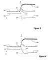
- FIG. 3 shows experimental results according to known bleeder circuits
- FIG. 4 shows experimental results according to embodiments
- FIG. 5 shows voltages and currents according to embodiments.
- FIG. 6 is an illustrative schematic showing a controllable bleeder circuit.
- FIG. 2 shows a schematic circuit diagram of a bleeder arrangement in a lighting circuit.
- the circuit 200 shows a phase-cut mains input 205 which is rectified by rectifier 210 .
- the rectified voltage is converted by means of a switched mode power converter (SMPC) 220 to provide the DC current supply to lighting unit 230 .
- SMPC switched mode power converter
- controller 240 also controls the bleeder circuit 250 .
- the bleeder circuit 250 comprises a pair of resistors 261 and 262 , and a bipolar transistor T 1 .
- the gate of transistor T 1 is controlled by the controller such that the bleeder circuit comprises a controllable current sink.
- the bleeder is enabled during a first part of the phase. Before the triac latches on, the output voltage is low, and thus the bleeder current is correspondingly low; however, it is sufficient to establish the synchronisation current 132 . When the leading-edge is reached, the triac switches on, the output voltage rises, and the bleeder provides a higher current—the latch current.
- the latching current is set in advance of the leading edge, as shown in FIG. 2 ; however, during the initial phase cut period the voltage across the current is low, so the current source is saturated and the current is limited, so that the full latching current only flows once the leading edge is reached.
- the latch current 134 is no longer required, and only a lower hold current 136 is needed.
- This hold current may be supplied by the LED lighting application itself, or may be supplied by a second, low-current bleeder, also known as a weak bleeder which remains permanently on. The bleeder may thus be switched off, once the triac has latched on.
- FIG. 3 shows experimental results according to known bleeder circuits.
- the bleeder current is shown at trace 310
- the triac output current at 320
- the triac output voltage is shown at 330 .
- oscillations are shown at 325 due to the switching off of the bleeder current at 315 , after the leading edge 322 , following a fixed delay D. As shown, the oscillations do not quite reach zero, and so the operation of the triac, and in particular its latching, is not interrupted. However, it will be appreciated that depending on the specific circuit, the oscillations 325 may cause the current to fall to or below zero in which case the triac may become unlatched and switch off.
- the bleeder is switched off in at least two stages. This is illustrated in FIG. 4 which shows experimental results according to embodiments.
- the bleeder current is shown at trace 410 , and the triac output current at 420 .
- the triac output voltage is shown at 430 .
- the bleeder current is not completely switched off at 425 but set to a lower value V; it is then gradually decreased as shown at 426 towards zero.
- a weak, or low current bleeder is then activated to maintain the holding current. In other embodiments which sink more current, this weak bleeder could stay off).
- FIG. 5 shows voltages and currents according to embodiments, in order to achieve the experimental results shown in FIG. 4 .
- the figure shows the same leading-edge dimmed voltage shape 120 as shown in FIG. 1 with phase cut first part 122 followed by the rise at edge 124 .
- Curve 510 indicates when the enable bleeder is enabled and curve 520 shows a soft-stop enable signal. As can be seen, the bleeder is enabled from the start of the phase until a specific moment 530 , which will be considered in more detail below.
- a soft-stop enable function 520 is turned on.
- the delay may typically be between 100 and 300 ⁇ s although values outside this range are not excluded, and in particular may be 150 ⁇ s. Such a delay is helpful to ensure a good ignition of the triac and to ensure that the device has properly latched on.
- the soft stop enable signal 520 initiates the soft stop function whereby the bleeder current is reduced to 0 but at the same time oscillations due to a sudden turn off are prevented.
- the soft-stop is a multistage function. In the example shown on FIG. 5 the soft-stop has two stages: the first stage occurs immediately soft-stop 520 is enabled, and this comprises a reduction in the bleeder current from its maximum to an intermediate value.
- the intermediate value is 50% of the maximum value I_bleed_Max, that is to say the intermediate value is 0.5*I_bleed_Max.
- a linear reduction there is no limitation to a linear reduction, and in other embodiments, other forms of reduction may be used: for example, an exponential reduction in the bleeder current may be provided or a part-exponential followed by a simple switch-off.
- the control is arranged so the specific moment 530 at the end of the bleeder enablement is coincident with the end of the soft-stop 520 .
- FIG. 6 is an illustrative schematic showing a controllable bleeder circuit.
- the circuit shows an IC 610 , which may comprise the controller 240 , which includes a digital control block 620 .
- Digital output from digital control block 620 is converted into an analog signal by digital-to-analog converter (DAC) 630 .
- DAC digital-to-analog converter
- the analogue signal is used to control the gate of bipolar transistor T 1 which forms part of the bleeder circuit 250 .
- the controller shown in FIG. 6 is digital, the invention is not limited thereto, and the soft-stop functionality could be provided by means of analog circuitry and signals.
Abstract
Description
Claims (12)
Applications Claiming Priority (3)
| Application Number | Priority Date | Filing Date | Title |
|---|---|---|---|
| EP11290587 | 2011-12-21 | ||
| EP11290587.2 | 2011-12-21 | ||
| EP11290587.2A EP2608637B1 (en) | 2011-12-21 | 2011-12-21 | Leading-edge phase-cut bleeder control |
Publications (2)
| Publication Number | Publication Date |
|---|---|
| US20140001979A1 US20140001979A1 (en) | 2014-01-02 |
| US8836226B2 true US8836226B2 (en) | 2014-09-16 |
Family
ID=45524304
Family Applications (1)
| Application Number | Title | Priority Date | Filing Date |
|---|---|---|---|
| US13/712,572 Active US8836226B2 (en) | 2011-12-21 | 2012-12-12 | Leading-edge phase-cut bleeder control |
Country Status (2)
| Country | Link |
|---|---|
| US (1) | US8836226B2 (en) |
| EP (1) | EP2608637B1 (en) |
Cited By (14)
| Publication number | Priority date | Publication date | Assignee | Title |
|---|---|---|---|---|
| US20150181669A1 (en) * | 2013-12-24 | 2015-06-25 | Nxp B.V. | Bleeder circuit controller |
| US9565782B2 (en) | 2013-02-15 | 2017-02-07 | Ecosense Lighting Inc. | Field replaceable power supply cartridge |
| US9568665B2 (en) | 2015-03-03 | 2017-02-14 | Ecosense Lighting Inc. | Lighting systems including lens modules for selectable light distribution |
| USD782093S1 (en) | 2015-07-20 | 2017-03-21 | Ecosense Lighting Inc. | LED luminaire having a mounting system |
| USD785218S1 (en) | 2015-07-06 | 2017-04-25 | Ecosense Lighting Inc. | LED luminaire having a mounting system |
| US9651232B1 (en) | 2015-08-03 | 2017-05-16 | Ecosense Lighting Inc. | Lighting system having a mounting device |
| US9651227B2 (en) | 2015-03-03 | 2017-05-16 | Ecosense Lighting Inc. | Low-profile lighting system having pivotable lighting enclosure |
| US9651216B2 (en) | 2015-03-03 | 2017-05-16 | Ecosense Lighting Inc. | Lighting systems including asymmetric lens modules for selectable light distribution |
| US9746159B1 (en) | 2015-03-03 | 2017-08-29 | Ecosense Lighting Inc. | Lighting system having a sealing system |
| US9869450B2 (en) | 2015-02-09 | 2018-01-16 | Ecosense Lighting Inc. | Lighting systems having a truncated parabolic- or hyperbolic-conical light reflector, or a total internal reflection lens; and having another light reflector |
| US10306724B2 (en) | 2017-01-15 | 2019-05-28 | Ecosense Lighting Inc. | Lighting systems, and systems for determining periodic values of a phase angle of a waveform power input |
| US10477636B1 (en) | 2014-10-28 | 2019-11-12 | Ecosense Lighting Inc. | Lighting systems having multiple light sources |
| US10483850B1 (en) | 2017-09-18 | 2019-11-19 | Ecosense Lighting Inc. | Universal input-voltage-compatible switched-mode power supply |
| US11306897B2 (en) | 2015-02-09 | 2022-04-19 | Ecosense Lighting Inc. | Lighting systems generating partially-collimated light emissions |
Families Citing this family (6)
| Publication number | Priority date | Publication date | Assignee | Title |
|---|---|---|---|---|
| JP6086318B2 (en) * | 2013-03-22 | 2017-03-01 | 東芝ライテック株式会社 | Power supply circuit and lighting device |
| EP2955978B1 (en) * | 2014-06-09 | 2023-08-09 | Silergy Semiconductor (Hong Kong) Limited | Lighting circuits, luminaries and methods compatible with phase-cut mains supplies |
| CN106664764B (en) | 2014-07-23 | 2019-01-22 | 飞利浦照明控股有限公司 | LED drive circuit, LED circuit and driving method |
| KR20160055694A (en) * | 2014-11-10 | 2016-05-18 | 페어차일드코리아반도체 주식회사 | Standby current supplier |
| CN106912144B (en) * | 2017-04-06 | 2018-01-23 | 矽力杰半导体技术(杭州)有限公司 | LED drive circuit, circuit module and control method with controllable silicon dimmer |
| CN106888524B (en) * | 2017-04-21 | 2018-01-16 | 矽力杰半导体技术(杭州)有限公司 | LED drive circuit, circuit module and control method with controllable silicon dimmer |
Citations (6)
| Publication number | Priority date | Publication date | Assignee | Title |
|---|---|---|---|---|
| US20100259196A1 (en) * | 2009-04-11 | 2010-10-14 | Innosys, Inc. | Low Current Thyristor-Based Dimming |
| EP2257124A1 (en) | 2009-05-29 | 2010-12-01 | Nxp B.V. | Circuit for connecting a low current lighting circuit to a dimmer |
| WO2010150183A1 (en) | 2009-06-25 | 2010-12-29 | Koninklijke Philips Electronics N.V. | Driver for cooperating with a wall dimmer |
| WO2011013060A2 (en) | 2009-07-27 | 2011-02-03 | Koninklijke Philips Electronics N.V. | Bleeder circuit |
| US20110291587A1 (en) * | 2007-03-12 | 2011-12-01 | Melanson John L | Multi-Function Duty Cycle Modifier |
| US20130300303A1 (en) * | 2011-04-13 | 2013-11-14 | Gang Gary Liu | Constant Voltage Dimmable LED Driver |
Family Cites Families (1)
| Publication number | Priority date | Publication date | Assignee | Title |
|---|---|---|---|---|
| EP2373124B1 (en) * | 2010-04-01 | 2013-10-23 | Rohm Co., Ltd. | Driver circuit for driving a lighting device and method for operating the same |
-
2011
- 2011-12-21 EP EP11290587.2A patent/EP2608637B1/en active Active
-
2012
- 2012-12-12 US US13/712,572 patent/US8836226B2/en active Active
Patent Citations (7)
| Publication number | Priority date | Publication date | Assignee | Title |
|---|---|---|---|---|
| US20110291587A1 (en) * | 2007-03-12 | 2011-12-01 | Melanson John L | Multi-Function Duty Cycle Modifier |
| US20100259196A1 (en) * | 2009-04-11 | 2010-10-14 | Innosys, Inc. | Low Current Thyristor-Based Dimming |
| EP2257124A1 (en) | 2009-05-29 | 2010-12-01 | Nxp B.V. | Circuit for connecting a low current lighting circuit to a dimmer |
| US20120056553A1 (en) * | 2009-05-29 | 2012-03-08 | Nxp B.V. | Circuit for connecting a low current lighting circuit to a dimmer |
| WO2010150183A1 (en) | 2009-06-25 | 2010-12-29 | Koninklijke Philips Electronics N.V. | Driver for cooperating with a wall dimmer |
| WO2011013060A2 (en) | 2009-07-27 | 2011-02-03 | Koninklijke Philips Electronics N.V. | Bleeder circuit |
| US20130300303A1 (en) * | 2011-04-13 | 2013-11-14 | Gang Gary Liu | Constant Voltage Dimmable LED Driver |
Non-Patent Citations (1)
| Title |
|---|
| Extended European Search Report for application No. 11290587.2 (Jul. 10, 2012). |
Cited By (16)
| Publication number | Priority date | Publication date | Assignee | Title |
|---|---|---|---|---|
| US9565782B2 (en) | 2013-02-15 | 2017-02-07 | Ecosense Lighting Inc. | Field replaceable power supply cartridge |
| US20150181669A1 (en) * | 2013-12-24 | 2015-06-25 | Nxp B.V. | Bleeder circuit controller |
| US9532416B2 (en) * | 2013-12-24 | 2016-12-27 | Silergy Corp. | Bleeder circuit controller |
| US10477636B1 (en) | 2014-10-28 | 2019-11-12 | Ecosense Lighting Inc. | Lighting systems having multiple light sources |
| US11614217B2 (en) | 2015-02-09 | 2023-03-28 | Korrus, Inc. | Lighting systems generating partially-collimated light emissions |
| US11306897B2 (en) | 2015-02-09 | 2022-04-19 | Ecosense Lighting Inc. | Lighting systems generating partially-collimated light emissions |
| US9869450B2 (en) | 2015-02-09 | 2018-01-16 | Ecosense Lighting Inc. | Lighting systems having a truncated parabolic- or hyperbolic-conical light reflector, or a total internal reflection lens; and having another light reflector |
| US9651216B2 (en) | 2015-03-03 | 2017-05-16 | Ecosense Lighting Inc. | Lighting systems including asymmetric lens modules for selectable light distribution |
| US9651227B2 (en) | 2015-03-03 | 2017-05-16 | Ecosense Lighting Inc. | Low-profile lighting system having pivotable lighting enclosure |
| US9746159B1 (en) | 2015-03-03 | 2017-08-29 | Ecosense Lighting Inc. | Lighting system having a sealing system |
| US9568665B2 (en) | 2015-03-03 | 2017-02-14 | Ecosense Lighting Inc. | Lighting systems including lens modules for selectable light distribution |
| USD785218S1 (en) | 2015-07-06 | 2017-04-25 | Ecosense Lighting Inc. | LED luminaire having a mounting system |
| USD782093S1 (en) | 2015-07-20 | 2017-03-21 | Ecosense Lighting Inc. | LED luminaire having a mounting system |
| US9651232B1 (en) | 2015-08-03 | 2017-05-16 | Ecosense Lighting Inc. | Lighting system having a mounting device |
| US10306724B2 (en) | 2017-01-15 | 2019-05-28 | Ecosense Lighting Inc. | Lighting systems, and systems for determining periodic values of a phase angle of a waveform power input |
| US10483850B1 (en) | 2017-09-18 | 2019-11-19 | Ecosense Lighting Inc. | Universal input-voltage-compatible switched-mode power supply |
Also Published As
| Publication number | Publication date |
|---|---|
| EP2608637B1 (en) | 2018-11-14 |
| EP2608637A1 (en) | 2013-06-26 |
| US20140001979A1 (en) | 2014-01-02 |
Similar Documents
| Publication | Publication Date | Title |
|---|---|---|
| US8836226B2 (en) | Leading-edge phase-cut bleeder control | |
| US10285229B2 (en) | LED driving circuit having SCR dimmer, circuit module and control method thereof | |
| US10887957B2 (en) | Light emitting diode drive circuit with silicon-controlled rectifier dimmer, circuit module and control method | |
| US10433384B2 (en) | LED driver with silicon controlled dimmer, apparatus and control method thereof | |
| US10958187B2 (en) | Load control device for high-efficiency loads | |
| US8692479B2 (en) | Method of controlling a ballast, a ballast, a lighting controller, and a digital signal processor | |
| EP2919563B1 (en) | Two-wire dimmer switch for low-power loads | |
| US11699946B2 (en) | Load control device having an overcurrent protection circuit | |
| US10375775B1 (en) | Circuit and method for linear constant current control and LED device | |
| US11051378B2 (en) | Eliminating flicker and open load protection for driver compatible with NAFTA dim ECG | |
| US20230223833A1 (en) | Load Control Device for High-Efficiency Loads | |
| CN108430139B (en) | LED driving circuit with silicon controlled rectifier dimmer and control method thereof | |
| EP3644691A1 (en) | Bleeder circuit and led driving circuit applying the same | |
| EP3095182B1 (en) | Two-wire load control device for low-power loads | |
| JP2015065772A (en) | Power-supply device, lighting fixture, and lighting system | |
| EP2806712A1 (en) | Application circuit and control method thereof | |
| CN110972356A (en) | Drive control circuit and lighting drive circuit of light emitting diode | |
| US9583073B1 (en) | Adaptive startup method for constant current LED drivers | |
| Liu et al. | Improvements in performance and reliability for segmented linear LED drivers | |
| US8558478B2 (en) | Hybrid lamp power circuit | |
| WO2011039664A1 (en) | Rapid start-up circuit for solid state lighting system | |
| US10462863B2 (en) | Dimmer interface having reduced power consumption |
Legal Events
| Date | Code | Title | Description |
|---|---|---|---|
| AS | Assignment |
Owner name: NXP B.V., NETHERLANDS Free format text: ASSIGNMENT OF ASSIGNORS INTEREST;ASSIGNORS:MERCIER, FREDERIC;DERRIEN, DAVID;PERQUIS, THIBAULT;REEL/FRAME:029456/0005 Effective date: 20121129 |
|
| STCF | Information on status: patent grant |
Free format text: PATENTED CASE |
|
| AS | Assignment |
Owner name: MORGAN STANLEY SENIOR FUNDING, INC., MARYLAND Free format text: SECURITY AGREEMENT SUPPLEMENT;ASSIGNOR:NXP B.V.;REEL/FRAME:038017/0058 Effective date: 20160218 |
|
| AS | Assignment |
Owner name: SILERGY CORP., UNITED KINGDOM Free format text: ASSIGNMENT OF ASSIGNORS INTEREST;ASSIGNOR:NXP B.V.;REEL/FRAME:038304/0598 Effective date: 20160405 |
|
| AS | Assignment |
Owner name: NXP B.V., NETHERLANDS Free format text: PATENT RELEASE;ASSIGNOR:MORGAN STANLEY SENIOR FUNDING, INC.;REEL/FRAME:039070/0577 Effective date: 20160603 |
|
| AS | Assignment |
Owner name: MORGAN STANLEY SENIOR FUNDING, INC., MARYLAND Free format text: CORRECTIVE ASSIGNMENT TO CORRECT THE REMOVE APPLICATION 12092129 PREVIOUSLY RECORDED ON REEL 038017 FRAME 0058. ASSIGNOR(S) HEREBY CONFIRMS THE SECURITY AGREEMENT SUPPLEMENT;ASSIGNOR:NXP B.V.;REEL/FRAME:039361/0212 Effective date: 20160218 |
|
| AS | Assignment |
Owner name: NXP B.V., NETHERLANDS Free format text: PATENT RELEASE;ASSIGNOR:MORGAN STANLEY SENIOR FUNDING, INC.;REEL/FRAME:039707/0471 Effective date: 20160805 |
|
| AS | Assignment |
Owner name: MORGAN STANLEY SENIOR FUNDING, INC., MARYLAND Free format text: CORRECTIVE ASSIGNMENT TO CORRECT THE REMOVE APPLICATION 12681366 PREVIOUSLY RECORDED ON REEL 039361 FRAME 0212. ASSIGNOR(S) HEREBY CONFIRMS THE SECURITY AGREEMENT SUPPLEMENT;ASSIGNOR:NXP B.V.;REEL/FRAME:042762/0145 Effective date: 20160218 Owner name: MORGAN STANLEY SENIOR FUNDING, INC., MARYLAND Free format text: CORRECTIVE ASSIGNMENT TO CORRECT THE REMOVE APPLICATION 12681366 PREVIOUSLY RECORDED ON REEL 038017 FRAME 0058. ASSIGNOR(S) HEREBY CONFIRMS THE SECURITY AGREEMENT SUPPLEMENT;ASSIGNOR:NXP B.V.;REEL/FRAME:042985/0001 Effective date: 20160218 |
|
| MAFP | Maintenance fee payment |
Free format text: PAYMENT OF MAINTENANCE FEE, 4TH YEAR, LARGE ENTITY (ORIGINAL EVENT CODE: M1551) Year of fee payment: 4 |
|
| AS | Assignment |
Owner name: NXP B.V., NETHERLANDS Free format text: RELEASE BY SECURED PARTY;ASSIGNOR:MORGAN STANLEY SENIOR FUNDING, INC.;REEL/FRAME:050745/0001 Effective date: 20190903 |
|
| AS | Assignment |
Owner name: MORGAN STANLEY SENIOR FUNDING, INC., MARYLAND Free format text: CORRECTIVE ASSIGNMENT TO CORRECT THE REMOVE APPLICATION 12298143 PREVIOUSLY RECORDED ON REEL 042762 FRAME 0145. ASSIGNOR(S) HEREBY CONFIRMS THE SECURITY AGREEMENT SUPPLEMENT;ASSIGNOR:NXP B.V.;REEL/FRAME:051145/0184 Effective date: 20160218 Owner name: MORGAN STANLEY SENIOR FUNDING, INC., MARYLAND Free format text: CORRECTIVE ASSIGNMENT TO CORRECT THE REMOVE APPLICATION 12298143 PREVIOUSLY RECORDED ON REEL 039361 FRAME 0212. ASSIGNOR(S) HEREBY CONFIRMS THE SECURITY AGREEMENT SUPPLEMENT;ASSIGNOR:NXP B.V.;REEL/FRAME:051029/0387 Effective date: 20160218 Owner name: MORGAN STANLEY SENIOR FUNDING, INC., MARYLAND Free format text: CORRECTIVE ASSIGNMENT TO CORRECT THE REMOVE APPLICATION 12298143 PREVIOUSLY RECORDED ON REEL 042985 FRAME 0001. ASSIGNOR(S) HEREBY CONFIRMS THE SECURITY AGREEMENT SUPPLEMENT;ASSIGNOR:NXP B.V.;REEL/FRAME:051029/0001 Effective date: 20160218 Owner name: MORGAN STANLEY SENIOR FUNDING, INC., MARYLAND Free format text: CORRECTIVE ASSIGNMENT TO CORRECT THE REMOVE APPLICATION 12298143 PREVIOUSLY RECORDED ON REEL 038017 FRAME 0058. ASSIGNOR(S) HEREBY CONFIRMS THE SECURITY AGREEMENT SUPPLEMENT;ASSIGNOR:NXP B.V.;REEL/FRAME:051030/0001 Effective date: 20160218 Owner name: MORGAN STANLEY SENIOR FUNDING, INC., MARYLAND Free format text: CORRECTIVE ASSIGNMENT TO CORRECT THE REMOVE APPLICATION12298143 PREVIOUSLY RECORDED ON REEL 039361 FRAME 0212. ASSIGNOR(S) HEREBY CONFIRMS THE SECURITY AGREEMENT SUPPLEMENT;ASSIGNOR:NXP B.V.;REEL/FRAME:051029/0387 Effective date: 20160218 Owner name: MORGAN STANLEY SENIOR FUNDING, INC., MARYLAND Free format text: CORRECTIVE ASSIGNMENT TO CORRECT THE REMOVE APPLICATION12298143 PREVIOUSLY RECORDED ON REEL 042985 FRAME 0001. ASSIGNOR(S) HEREBY CONFIRMS THE SECURITY AGREEMENT SUPPLEMENT;ASSIGNOR:NXP B.V.;REEL/FRAME:051029/0001 Effective date: 20160218 Owner name: MORGAN STANLEY SENIOR FUNDING, INC., MARYLAND Free format text: CORRECTIVE ASSIGNMENT TO CORRECT THE REMOVE APPLICATION12298143 PREVIOUSLY RECORDED ON REEL 042762 FRAME 0145. ASSIGNOR(S) HEREBY CONFIRMS THE SECURITY AGREEMENT SUPPLEMENT;ASSIGNOR:NXP B.V.;REEL/FRAME:051145/0184 Effective date: 20160218 |
|
| AS | Assignment |
Owner name: SILERGY SEMICONDUCTOR (HONG KONG) LTD., HONG KONG Free format text: ASSIGNMENT OF ASSIGNORS INTEREST;ASSIGNOR:SILERGY CORP.;REEL/FRAME:054751/0393 Effective date: 20201203 |
|
| MAFP | Maintenance fee payment |
Free format text: PAYMENT OF MAINTENANCE FEE, 8TH YEAR, LARGE ENTITY (ORIGINAL EVENT CODE: M1552); ENTITY STATUS OF PATENT OWNER: LARGE ENTITY Year of fee payment: 8 |