US8834057B2 - Slip bracket connector for rigid members - Google Patents
Slip bracket connector for rigid members Download PDFInfo
- Publication number
- US8834057B2 US8834057B2 US13/628,408 US201213628408A US8834057B2 US 8834057 B2 US8834057 B2 US 8834057B2 US 201213628408 A US201213628408 A US 201213628408A US 8834057 B2 US8834057 B2 US 8834057B2
- Authority
- US
- United States
- Prior art keywords
- wood member
- section
- brace
- wood
- baluster
- Prior art date
- Legal status (The legal status is an assumption and is not a legal conclusion. Google has not performed a legal analysis and makes no representation as to the accuracy of the status listed.)
- Expired - Fee Related
Links
- 239000002023 wood Substances 0.000 claims abstract description 57
- 239000002184 metal Substances 0.000 claims abstract description 13
- 238000010276 construction Methods 0.000 abstract description 7
- 230000008602 contraction Effects 0.000 abstract description 3
- 230000006378 damage Effects 0.000 description 5
- 238000005452 bending Methods 0.000 description 4
- 208000027418 Wounds and injury Diseases 0.000 description 2
- 230000003466 anti-cipated effect Effects 0.000 description 2
- 238000000576 coating method Methods 0.000 description 2
- 238000010586 diagram Methods 0.000 description 2
- 208000014674 injury Diseases 0.000 description 2
- 239000000463 material Substances 0.000 description 2
- 238000000034 method Methods 0.000 description 2
- 229910001335 Galvanized steel Inorganic materials 0.000 description 1
- 238000010521 absorption reaction Methods 0.000 description 1
- 230000001154 acute effect Effects 0.000 description 1
- 230000004888 barrier function Effects 0.000 description 1
- 239000011248 coating agent Substances 0.000 description 1
- 239000002131 composite material Substances 0.000 description 1
- 230000008020 evaporation Effects 0.000 description 1
- 238000001704 evaporation Methods 0.000 description 1
- 210000003195 fascia Anatomy 0.000 description 1
- 239000008397 galvanized steel Substances 0.000 description 1
- 239000000203 mixture Substances 0.000 description 1
- 238000012986 modification Methods 0.000 description 1
- 230000004048 modification Effects 0.000 description 1
- 239000000843 powder Substances 0.000 description 1
- 238000009877 rendering Methods 0.000 description 1
- 238000010008 shearing Methods 0.000 description 1
- 230000036962 time dependent Effects 0.000 description 1
Images


Classifications
-
- F—MECHANICAL ENGINEERING; LIGHTING; HEATING; WEAPONS; BLASTING
- F16—ENGINEERING ELEMENTS AND UNITS; GENERAL MEASURES FOR PRODUCING AND MAINTAINING EFFECTIVE FUNCTIONING OF MACHINES OR INSTALLATIONS; THERMAL INSULATION IN GENERAL
- F16B—DEVICES FOR FASTENING OR SECURING CONSTRUCTIONAL ELEMENTS OR MACHINE PARTS TOGETHER, e.g. NAILS, BOLTS, CIRCLIPS, CLAMPS, CLIPS OR WEDGES; JOINTS OR JOINTING
- F16B7/00—Connections of rods or tubes, e.g. of non-circular section, mutually, including resilient connections
- F16B7/04—Clamping or clipping connections
- F16B7/044—Clamping or clipping connections for rods or tubes being in angled relationship
- F16B7/048—Clamping or clipping connections for rods or tubes being in angled relationship for rods or for tubes without using the innerside thereof
- F16B7/0493—Clamping or clipping connections for rods or tubes being in angled relationship for rods or for tubes without using the innerside thereof forming a crossed-over connection
-
- F—MECHANICAL ENGINEERING; LIGHTING; HEATING; WEAPONS; BLASTING
- F16—ENGINEERING ELEMENTS AND UNITS; GENERAL MEASURES FOR PRODUCING AND MAINTAINING EFFECTIVE FUNCTIONING OF MACHINES OR INSTALLATIONS; THERMAL INSULATION IN GENERAL
- F16B—DEVICES FOR FASTENING OR SECURING CONSTRUCTIONAL ELEMENTS OR MACHINE PARTS TOGETHER, e.g. NAILS, BOLTS, CIRCLIPS, CLAMPS, CLIPS OR WEDGES; JOINTS OR JOINTING
- F16B7/00—Connections of rods or tubes, e.g. of non-circular section, mutually, including resilient connections
-
- B—PERFORMING OPERATIONS; TRANSPORTING
- B23—MACHINE TOOLS; METAL-WORKING NOT OTHERWISE PROVIDED FOR
- B23P—METAL-WORKING NOT OTHERWISE PROVIDED FOR; COMBINED OPERATIONS; UNIVERSAL MACHINE TOOLS
- B23P11/00—Connecting or disconnecting metal parts or objects by metal-working techniques not otherwise provided for
-
- F—MECHANICAL ENGINEERING; LIGHTING; HEATING; WEAPONS; BLASTING
- F16—ENGINEERING ELEMENTS AND UNITS; GENERAL MEASURES FOR PRODUCING AND MAINTAINING EFFECTIVE FUNCTIONING OF MACHINES OR INSTALLATIONS; THERMAL INSULATION IN GENERAL
- F16B—DEVICES FOR FASTENING OR SECURING CONSTRUCTIONAL ELEMENTS OR MACHINE PARTS TOGETHER, e.g. NAILS, BOLTS, CIRCLIPS, CLAMPS, CLIPS OR WEDGES; JOINTS OR JOINTING
- F16B2200/00—Constructional details of connections not covered for in other groups of this subclass
- F16B2200/50—Flanged connections
- F16B2200/503—Flanged connections the flange being separate from the elements to be connected
-
- Y—GENERAL TAGGING OF NEW TECHNOLOGICAL DEVELOPMENTS; GENERAL TAGGING OF CROSS-SECTIONAL TECHNOLOGIES SPANNING OVER SEVERAL SECTIONS OF THE IPC; TECHNICAL SUBJECTS COVERED BY FORMER USPC CROSS-REFERENCE ART COLLECTIONS [XRACs] AND DIGESTS
- Y10—TECHNICAL SUBJECTS COVERED BY FORMER USPC
- Y10T—TECHNICAL SUBJECTS COVERED BY FORMER US CLASSIFICATION
- Y10T29/00—Metal working
- Y10T29/49—Method of mechanical manufacture
- Y10T29/49826—Assembling or joining
- Y10T29/49833—Punching, piercing or reaming part by surface of second part
-
- Y—GENERAL TAGGING OF NEW TECHNOLOGICAL DEVELOPMENTS; GENERAL TAGGING OF CROSS-SECTIONAL TECHNOLOGIES SPANNING OVER SEVERAL SECTIONS OF THE IPC; TECHNICAL SUBJECTS COVERED BY FORMER USPC CROSS-REFERENCE ART COLLECTIONS [XRACs] AND DIGESTS
- Y10—TECHNICAL SUBJECTS COVERED BY FORMER USPC
- Y10T—TECHNICAL SUBJECTS COVERED BY FORMER US CLASSIFICATION
- Y10T29/00—Metal working
- Y10T29/49—Method of mechanical manufacture
- Y10T29/49826—Assembling or joining
- Y10T29/49947—Assembling or joining by applying separate fastener
- Y10T29/49948—Multipart cooperating fastener [e.g., bolt and nut]
- Y10T29/4995—Nonthreaded
-
- Y—GENERAL TAGGING OF NEW TECHNOLOGICAL DEVELOPMENTS; GENERAL TAGGING OF CROSS-SECTIONAL TECHNOLOGIES SPANNING OVER SEVERAL SECTIONS OF THE IPC; TECHNICAL SUBJECTS COVERED BY FORMER USPC CROSS-REFERENCE ART COLLECTIONS [XRACs] AND DIGESTS
- Y10—TECHNICAL SUBJECTS COVERED BY FORMER USPC
- Y10T—TECHNICAL SUBJECTS COVERED BY FORMER US CLASSIFICATION
- Y10T403/00—Joints and connections
- Y10T403/32—Articulated members
Definitions
- This invention relates to rigid connectors for joining two intersecting rigid members.
- This invention relates particularly to a rigid one-piece connector that perpendicularly joins two rigid wood members while allowing slip movement in one of the members.
- Wood beams, posts, joists, balusters, and the like referred to collectively herein as “members,” naturally shrink and expand due to the composition of the wood.
- a wood member can decrease and increase in length due to shrinkage and expansion in the direction of the wood grain.
- Frequent fluctuations of 3% are common, and fluctuations of as much as 18% may occur depending on the moisture content of the wood and the surrounding environment. Radial dimension changes also occur, although typically less drastically than length fluctuations.
- conventional construction techniques largely ignore them, often to significant structural detriment.
- the members are attached with a fastener, such as a nail or screw.
- Other known attachment devices include metal plate connectors that conform to the shape of the joint between the members. These metal plates are attached with fasteners to both members to create a “strong” or “rigid tie” that does not account for the dimensional fluctuations in the members. Once construction is complete, over time these fluctuations impart considerable tension forces on the members, the attachment devices, and related attached structural components. The tension forces may loosen the attachments across the joint, damage the wood, and otherwise warp the original shape and support capabilities of the constructed members.
- balustrades While there are indeed requirements that some connections be rigid, in many instances the anticipated shrinkage of the wood member must be a consideration within the design and construction of wooden member connections.
- wood balustrades would benefit from a wood member connector that addresses the natural dimensional fluctuations.
- a balustrade is composed of several vertically-oriented balusters attached to top and bottom rails and spaced evenly apart so as to act as a guard rail or other barrier.
- the balusters are attached by nails or screws driven through each baluster at the upper and lower ends. The balusters then strain against the fasteners due to the dimensional fluctuations. Eventually, the fasteners begin to pull out, the wood splinters, or the contraction pulls the rails out of alignment, leading to significant safety hazards.
- a connector for balusters that accommodates the dimensional fluctuations is needed.
- a bracket connector attaches a first wood member to a second wood member while allowing for a slip movement by the first member to accommodate dimensional fluctuations in the first member while it is securely fixed at one end.
- the connector fits around the perimeter of the first member, leaving a clearance gap that is thin enough to secure the first member laterally but wide enough to allow for natural radial and longitudinal expansion of the first member.
- the connector attaches to the second member with one or more nails, screws, or other fasteners.
- the connector does not securely attach to the first member, which allows for the slip movement along the first member's longitudinal axis.
- the several illustrated embodiments show the bracket connector as a u-shaped thin metal bracket sized to fit around a deck baluster, a ceiling joist, or a square support post, but applications to other wood members are contemplated.
- FIG. 1 is a top rear left isometric view of a first embodiment of the present invention.
- FIG. 2 is a top view of the first embodiment of the present invention.
- FIG. 3 is a front view of the first embodiment of the present invention.
- FIG. 4 is a right side view of the first embodiment of the present invention.
- FIG. 5 is a diagram of a stamping pattern for fabricating the first embodiment of the present invention.
- FIG. 6 is a top front right isometric view of the first embodiment of the present invention placed over a baluster.
- FIG. 7 is a front view of a portion of a balustrade constructed using the first embodiment of the present invention.
- FIG. 8 is a cross-sectional side view of the balustrade taken along line 8 - 8 of FIG. 7 .
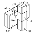
- FIG. 9 is a top front left isometric view of a second embodiment of the present invention.
- FIG. 10 is a top front left isometric view of the second embodiment of the present invention placed over a baluster and a lower deck rail.
- FIG. 11 is a diagram of a stamping pattern for fabricating the second embodiment of the present invention.
- FIG. 12 is a top front right isometric view of a third embodiment of the present invention placed over a cross beam.
- FIG. 13 is a top front right isometric view of a fourth embodiment of the present invention placed over a cross beam.
- FIGS. 1-5 there is illustrated a first embodiment of the present invention designated generally as 10 which is a one-piece bracket connector used to attach a first wood member to a second wood member while allowing the first wood member to fluctuate dimensionally according to the environment and the natural properties of the wood.
- a front portion 11 is attached to, and preferably integral with, a left portion 12 and a right portion 13 to form a three-sided brace.
- the left and right portions 12 , 13 are perpendicular to the front portion 11 and parallel to each other so that the brace is u-shaped. See FIG. 2 .
- one or both of the left and right portions 12 , 13 may intersect the front portion 11 at an acute or obtuse angle to accommodate non-square, non-rectangular first wood members, such as trapezoidal beams.
- the left and right portions 12 , 13 may alternatively intersect each other to form a triangular beam having an apex at the intersection of the portions 12 , 13 instead of a front portion 11 .
- Left and right tabs 14 , 15 are attached to, and preferably integral with, the left and right portions 12 , 13 , respectively, at the rear edge of each portion 12 , 13 .
- the tabs 14 , 15 project laterally from their respective portions 12 , 13 substantially parallel to the front portion 11 .
- the tabs 14 , 15 are narrower than the left and right portions 12 , 13 and are centered along the rear edge of the portions 12 , 13 .
- the tabs 14 , 15 are preferably coplanar so that the tabs 14 , 15 together make flush contact with the planar attachment surface of the second wood member as described below.
- One or more apertures 16 are disposed through each tab 14 , 15 .
- the apertures 16 each receive a fastener, preferably a screw, for securely attaching the device 10 to the second wood member.
- the apertures 16 in each tab 14 , 15 are offset from each other, most preferably by placing one aperture 16 at the top of its tab and the other aperture at the bottom of its tab. The offset positioning minimizes the potential for the second wood member to split along its grain when the fasteners are driven into it.
- the device 10 is preferably formed from a single piece of sheet metal, rendering each of the device 10 components substantially planar.
- the illustrated first embodiment of the device 10 may be stamped out of the sheet metal as shown in FIG. 5 .
- Stress relief punches 17 may be formed at each juncture of the components to facilitate bending of the sheet into the proper device 10 configuration without imparting undue stress on the components along the bend lines.
- the stamped metal is folded at 90 degree angles up out of the page at first and second up-fold lines 21 , 22 , and folded at 90 degree angles down into the page at first and second down-fold lines 23 , 24 .
- Each bend requires a material bend allowance to maintain proper final dimensions after bending of the part is accomplished.
- Rear corners 20 of the left and right portions 12 , 13 may be linearly cut or rounded to prevent damage or injury from the sharp corner.
- the device 10 may be die stamped, cast, molded, or extruded, and may be a structural composite material instead of metal.
- the preferred metal is galvanized steel, which may be untreated or treated with one or more coatings, such as a colored powder coating.
- FIGS. 6-8 illustrate the first embodiment of the present invention used to attach a baluster 51 within a typical wood deck having the following components: deck planks 57 are attached to one or more structural joists 59 ; vertical support posts 53 extend upward from the deck planks 57 ; a fascia 56 is attached to the ends of the joists 59 and may further be attached to the lower ends of the support posts 53 to hide the joists 59 from view; a guard rail, or balustrade, is formed with an upper rail 55 and lower rail 52 attached between support posts 53 parallel to the deck planks 57 , and a plurality of balusters 51 attached perpendicularly to the upper and lower rails 55 , 52 ; a top plate 54 is attached to the support posts 53 and may further be attached at intervals to the upper rail 55 .
- the balusters 51 are attached with a rigid securement, typically one or two nails or screws driven through the baluster 51 , to each rail 55 , 52 on the face of the rails 55 , 52 that faces away from the deck surface.
- the rigid securement prevents natural dimensional fluctuations and imparts tension forces on the baluster 51 , the fasteners, and any attached components.
- the resulting failures of this construction include the drawing downward and bowing of the upper rail 55 from the top plate 54 between the support posts 53 ; and securement failure of the balusters 51 , potentially leading to serious consequences in the event of a foreseeable user fall event.
- the balusters 51 mounted on the outside of the deck surface, the failure of the lower baluster 51 securement will often not be noticed by the home or cabin owner, particularly in instances of high elevation decks.
- the device 10 mitigates the above time-dependent baluster 51 failure, as the device 10 provides for vertical tension relief of the baluster 51 during foreseeable and anticipated baluster 51 shrinkage.
- the vertical tension relief also allows for minor baluster 51 expansion during periods of wetness for outdoor deck railings.
- the device With the upper end of the baluster 51 conventionally secured to the upper deck rail 55 by a rigid connection, such as by one or more securement screws 58 , the device fits around the baluster 51 and is secured to the lower deck rail 52 using two wood screws 19 driven through the apertures 16 of the device 10 into the attachment surface of the lower deck rail 52 .
- the baluster 51 With a rigid attachment at the upper end and no rigid attachment at the lower end, the baluster 51 is allowed any amount of slip movement resulting from dimensional fluctuations along its longitudinal axis, which in this embodiment is perpendicular to the ground. Further, the dimensions of the front, left, and right portions 11 - 13 are selected to leave a slight clearance gap 40 between the device 10 and the baluster 51 to allow longitudinal and radial movement of the baluster 51 while still horizontally securing the baluster 51 to prevent the baluster 51 from being kicked out by an impact force. The contained baluster 51 is thus allowed dimensional variation under conditions of contraction or expansion caused by commensurate wood moisture evaporation or absorption.
- FIGS. 9-11 illustrate a second embodiment of the device 10 , which may also be used to secure balusters 51 in a balustrade.
- the front portion 11 is attached to or integral with the left and right portions 12 , 13 as in the first embodiment.
- the left and right tabs 14 , 15 of the first embodiment are modified in the second embodiment to comprise a parallel section 14 A, 15 A and a perpendicular section 14 B, 15 B.
- the parallel sections 14 A, 15 A are attached to or integral with their corresponding portions 12 , 13 at the rear edge of each portion 12 , 13 .
- the parallel sections 14 A, 15 A project laterally from their respective portions 12 , 13 substantially parallel to the front portion 11 .
- the parallel sections 14 A, 15 A are preferably coplanar so that the parallel sections 14 A, 15 A together contact the side of the second wood member.
- the top edge of each parallel section 14 A, 15 A aligns with the top edge of its corresponding portion 12 , 13 .
- a perpendicular section 14 B, 15 B is attached to or integral with each corresponding parallel section 14 A, 15 A and extends to the rearward aspect of the device 10 perpendicularly from the parallel section 14 A, 15 A.
- One or more apertures may be disposed through each of the parallel sections 14 A, 15 A and perpendicular sections 14 B, 15 B.
- one aperture 16 is disposed through each of the perpendicular sections 14 B, 15 B, allowing fasteners to be driven into the top of the second wood member.
- forces imparted on the screws by the baluster 51 will be shearing forces rather than tension forces.
- screws and nails are configured to withstand much greater forces in shear than in tension.
- the position of each aperture 16 is offset with respect to the positions of the other apertures 16 to reduce or prevent splitting of the second wood member as described above.
- the illustrated second embodiment of the device 10 may be stamped out of sheet metal as shown in FIG. 11 .
- Stress relief punches 17 may be formed at each juncture of the components to facilitate bending of the sheet into the proper device 10 configuration without imparting undue stress on the components.
- the stamped metal is folded at 90 degree angles up out of the page at first and second up-fold lines 21 , 22 and third and fourth up-fold lines 31 , 32 , and folded at 90 degree angles down into the page at first and second down-fold lines 23 , 24 .
- Each bend requires a material bend allowance to maintain proper final dimensions after bending of the part is accomplished.
- Rear corners 20 of the right and left portions 12 , 13 may be linearly cut or rounded to prevent damage or injury from the sharp corner.
- FIG. 12 illustrates a third embodiment of the device 10 used to attach a rectangular first wood member, such as a wall stud or ceiling joist 41 , to a second wood member, such as a floor plate or joist 42 .
- the axis of the first wood member, and therefore the axis of the device 10 is horizontal rather than vertical. Further, the dimension of the device 10 from front to rear aspect is longer to accommodate the additional width of the first wood member.
- the device 10 secures a larger square support beam 43 to a wide support beam 44 .
Abstract
Description
Claims (13)
Priority Applications (3)
| Application Number | Priority Date | Filing Date | Title |
|---|---|---|---|
| US13/628,408 US8834057B2 (en) | 2012-09-27 | 2012-09-27 | Slip bracket connector for rigid members |
| US14/204,246 US8910367B2 (en) | 2012-09-27 | 2014-03-11 | Slip bracket connector for rigid members |
| US14/558,613 US9200653B2 (en) | 2012-09-27 | 2014-12-02 | Slip bracket connector for rigid members |
Applications Claiming Priority (1)
| Application Number | Priority Date | Filing Date | Title |
|---|---|---|---|
| US13/628,408 US8834057B2 (en) | 2012-09-27 | 2012-09-27 | Slip bracket connector for rigid members |
Related Child Applications (1)
| Application Number | Title | Priority Date | Filing Date |
|---|---|---|---|
| US14/204,246 Continuation US8910367B2 (en) | 2012-09-27 | 2014-03-11 | Slip bracket connector for rigid members |
Publications (2)
| Publication Number | Publication Date |
|---|---|
| US20140082921A1 US20140082921A1 (en) | 2014-03-27 |
| US8834057B2 true US8834057B2 (en) | 2014-09-16 |
Family
ID=50337437
Family Applications (3)
| Application Number | Title | Priority Date | Filing Date |
|---|---|---|---|
| US13/628,408 Expired - Fee Related US8834057B2 (en) | 2012-09-27 | 2012-09-27 | Slip bracket connector for rigid members |
| US14/204,246 Expired - Fee Related US8910367B2 (en) | 2012-09-27 | 2014-03-11 | Slip bracket connector for rigid members |
| US14/558,613 Expired - Fee Related US9200653B2 (en) | 2012-09-27 | 2014-12-02 | Slip bracket connector for rigid members |
Family Applications After (2)
| Application Number | Title | Priority Date | Filing Date |
|---|---|---|---|
| US14/204,246 Expired - Fee Related US8910367B2 (en) | 2012-09-27 | 2014-03-11 | Slip bracket connector for rigid members |
| US14/558,613 Expired - Fee Related US9200653B2 (en) | 2012-09-27 | 2014-12-02 | Slip bracket connector for rigid members |
Country Status (1)
| Country | Link |
|---|---|
| US (3) | US8834057B2 (en) |
Cited By (5)
| Publication number | Priority date | Publication date | Assignee | Title |
|---|---|---|---|---|
| US20140119811A1 (en) * | 2012-11-01 | 2014-05-01 | Coulter Ventures Llc D/B/A Rogue Fitness | Exercise equipment, connector or anchor, and method of making same |
| US20190136520A1 (en) * | 2017-11-03 | 2019-05-09 | Simpson Strong-Tie Company Inc. | Box Head Connector |
| US20210062536A1 (en) * | 2019-09-03 | 2021-03-04 | David Dench | Adjustable Fence Post Coupler |
| US11274440B2 (en) * | 2017-12-29 | 2022-03-15 | Certainteed Ceilings Corporation | Suspension ceiling support clip |
| US11891831B1 (en) * | 2018-07-17 | 2024-02-06 | Ameristar Perimeter Security Usa Inc. | Infill-covered barrier |
Families Citing this family (33)
| Publication number | Priority date | Publication date | Assignee | Title |
|---|---|---|---|---|
| US8834057B2 (en) * | 2012-09-27 | 2014-09-16 | Bti, Inc. | Slip bracket connector for rigid members |
| US9964255B2 (en) | 2014-10-03 | 2018-05-08 | DISH Technologies L.L.C. | Behind-wall television monitor wall mount |
| US9631770B2 (en) * | 2015-04-06 | 2017-04-25 | Edward James Holestine | Bracket for fixing a panel to a t-post |
| EP3093507A1 (en) * | 2015-05-14 | 2016-11-16 | Borgwarner Emissions Systems Spain, S.L.U. | Fixing anchor |
| CN105179401A (en) * | 2015-09-14 | 2015-12-23 | 重庆博荣拓尔科技有限公司 | Novel extension pipe |
| CN105156423A (en) * | 2015-09-14 | 2015-12-16 | 重庆博荣拓尔科技有限公司 | Shrinkage tube clamping device |
| US9945091B1 (en) * | 2016-10-13 | 2018-04-17 | Subsurface, Inc. | Portable cofferdam system |
| US20180238041A1 (en) | 2017-02-21 | 2018-08-23 | Styrc Jacek | Modular furniture system |
| GB2562754B (en) * | 2017-05-24 | 2019-12-11 | Marry Patrick | A fence fastener device |
| USD842684S1 (en) * | 2017-07-18 | 2019-03-12 | John House | Toeboard support bracket |
| USD887025S1 (en) | 2017-11-17 | 2020-06-09 | 2724889 Ontario Inc. | Connector for a modular structure |
| USD897189S1 (en) * | 2018-07-31 | 2020-09-29 | Dexion (New Zealand) Limited | Baseplate for racking and shelving systems |
| USD936468S1 (en) * | 2019-12-19 | 2021-11-23 | Troax AB | Fastening device |
| USD952382S1 (en) | 2020-02-04 | 2022-05-24 | 2724889 Ontario Inc. | Table |
| USD938771S1 (en) * | 2020-02-04 | 2021-12-21 | 2724889 Ontario Inc. | Connector |
| USD936859S1 (en) | 2020-02-04 | 2021-11-23 | 2724889 Ontario Inc. | Connector |
| USD938770S1 (en) * | 2020-02-04 | 2021-12-21 | 2724889 Ontario Inc. | Connector |
| USD952384S1 (en) | 2020-02-04 | 2022-05-24 | 2724889 Ontario Inc. | Leg |
| USD938772S1 (en) * | 2020-02-04 | 2021-12-21 | 2724889 Ontario Inc. | Connector |
| USD955865S1 (en) * | 2020-06-09 | 2022-06-28 | Mafi Ab | Fastening device |
| USD946389S1 (en) * | 2020-06-09 | 2022-03-22 | Mafi Ab | Fastening device |
| USD941131S1 (en) * | 2020-06-17 | 2022-01-18 | Mafi Ab | Fastening device |
| USD936247S1 (en) | 2020-08-12 | 2021-11-16 | 2724889 Ontario Inc. | Connector for a modular structure |
| USD936246S1 (en) | 2020-08-12 | 2021-11-16 | 2724889 Ontario Inc. | Connector for a modular structure |
| USD939106S1 (en) | 2020-08-12 | 2021-12-21 | 2724889 Ontario Inc. | Connector for a modular structure |
| USD938619S1 (en) | 2020-08-12 | 2021-12-14 | 2724889 Ontario Inc. | Connector for a modular structure |
| USD939731S1 (en) | 2020-08-12 | 2021-12-28 | 2724889 Ontario Inc. | Connector for a modular structure |
| USD938068S1 (en) | 2020-08-12 | 2021-12-07 | 2724889 Ontario Inc. | Connector for a modular structure |
| USD936861S1 (en) | 2020-08-12 | 2021-11-23 | 2724889 Ontario Inc. | Connector for a modular structure |
| TWI753635B (en) * | 2020-11-03 | 2022-01-21 | 香港商冠捷投資有限公司 | connection device |
| USD944633S1 (en) * | 2020-11-25 | 2022-03-01 | Mafi Ab | Fastening device |
| USD979387S1 (en) * | 2021-10-26 | 2023-02-28 | Mafi Group AB | Fastening device |
| USD985378S1 (en) * | 2021-10-28 | 2023-05-09 | Mafi Group AB | Fastening device |
Citations (9)
| Publication number | Priority date | Publication date | Assignee | Title |
|---|---|---|---|---|
| US1348765A (en) * | 1919-07-15 | 1920-08-03 | John B Weeks | Picket-fence strand |
| US3615110A (en) * | 1969-04-21 | 1971-10-26 | James E Fugate | Demountable sockets for guardrail posts |
| US4028899A (en) * | 1976-01-14 | 1977-06-14 | Carmichael Iii Daniel A | Anchoring system for a floating dock |
| US5150982A (en) | 1990-03-09 | 1992-09-29 | Simpson Strong-Tie Company, Inc. | Deck post tie |
| US5297890A (en) * | 1992-02-20 | 1994-03-29 | Simpson Strong-Tie Company, Inc. | Wood-to-pipe connection |
| US5560156A (en) * | 1995-07-31 | 1996-10-01 | Mcdonald; Kenneth O. | Hurricane tie-down |
| US5598680A (en) * | 1993-12-13 | 1997-02-04 | Wilhelmi; Juergen | Joining element for joining wooden components |
| US5836131A (en) | 1994-12-22 | 1998-11-17 | Super Stud Building Products | Joist hanger |
| US7153064B2 (en) * | 2005-02-25 | 2006-12-26 | Playstar, Inc. | Pipe sleeve for a floating dock |
Family Cites Families (9)
| Publication number | Priority date | Publication date | Assignee | Title |
|---|---|---|---|---|
| US4685576A (en) * | 1984-11-09 | 1987-08-11 | Seymour Mfg. Co. | Three axis corner bracket |
| US5186571A (en) * | 1991-01-07 | 1993-02-16 | Desco Corporation | Fence rail bracket |
| US5771646A (en) * | 1997-06-05 | 1998-06-30 | Action Sales & Marketing Inc | Railing post reinforcement bracket |
| US5961242A (en) * | 1997-11-28 | 1999-10-05 | Iron Eagle Industries Inc. | Bracket for a fencing system |
| US6446409B1 (en) * | 1999-10-13 | 2002-09-10 | Full Circle Industries, Inc. | Structural bracket for securing spanning and supporting members |
| US7866635B2 (en) * | 2005-01-07 | 2011-01-11 | Payne Fence Products, Llc | Fence system |
| US7427055B2 (en) * | 2005-12-13 | 2008-09-23 | Platt Robert E | Mounting bracket and snap-on cover assembly for use therewith |
| US8429805B1 (en) * | 2011-10-19 | 2013-04-30 | Willard B. Adkins | Railing and method of manufacture |
| US8834057B2 (en) * | 2012-09-27 | 2014-09-16 | Bti, Inc. | Slip bracket connector for rigid members |
-
2012
- 2012-09-27 US US13/628,408 patent/US8834057B2/en not_active Expired - Fee Related
-
2014
- 2014-03-11 US US14/204,246 patent/US8910367B2/en not_active Expired - Fee Related
- 2014-12-02 US US14/558,613 patent/US9200653B2/en not_active Expired - Fee Related
Patent Citations (9)
| Publication number | Priority date | Publication date | Assignee | Title |
|---|---|---|---|---|
| US1348765A (en) * | 1919-07-15 | 1920-08-03 | John B Weeks | Picket-fence strand |
| US3615110A (en) * | 1969-04-21 | 1971-10-26 | James E Fugate | Demountable sockets for guardrail posts |
| US4028899A (en) * | 1976-01-14 | 1977-06-14 | Carmichael Iii Daniel A | Anchoring system for a floating dock |
| US5150982A (en) | 1990-03-09 | 1992-09-29 | Simpson Strong-Tie Company, Inc. | Deck post tie |
| US5297890A (en) * | 1992-02-20 | 1994-03-29 | Simpson Strong-Tie Company, Inc. | Wood-to-pipe connection |
| US5598680A (en) * | 1993-12-13 | 1997-02-04 | Wilhelmi; Juergen | Joining element for joining wooden components |
| US5836131A (en) | 1994-12-22 | 1998-11-17 | Super Stud Building Products | Joist hanger |
| US5560156A (en) * | 1995-07-31 | 1996-10-01 | Mcdonald; Kenneth O. | Hurricane tie-down |
| US7153064B2 (en) * | 2005-02-25 | 2006-12-26 | Playstar, Inc. | Pipe sleeve for a floating dock |
Non-Patent Citations (1)
| Title |
|---|
| Green, David W. "Moisture Content and the Shrinkage of Lumber", U. S. Department of Agriculture, Forest Products Laboratory, Research Paper FPL-RP-489, Jan. 1989, 11 pages. |
Cited By (8)
| Publication number | Priority date | Publication date | Assignee | Title |
|---|---|---|---|---|
| US20140119811A1 (en) * | 2012-11-01 | 2014-05-01 | Coulter Ventures Llc D/B/A Rogue Fitness | Exercise equipment, connector or anchor, and method of making same |
| US9409220B2 (en) * | 2012-11-01 | 2016-08-09 | Coulter Ventures, LLC | Exercise equipment, connector or anchor, and method of making same |
| US20190136520A1 (en) * | 2017-11-03 | 2019-05-09 | Simpson Strong-Tie Company Inc. | Box Head Connector |
| US11078665B2 (en) * | 2017-11-03 | 2021-08-03 | Simpson Strong-Tie Company, Inc. | Box head connector |
| US11274440B2 (en) * | 2017-12-29 | 2022-03-15 | Certainteed Ceilings Corporation | Suspension ceiling support clip |
| US11891831B1 (en) * | 2018-07-17 | 2024-02-06 | Ameristar Perimeter Security Usa Inc. | Infill-covered barrier |
| US20210062536A1 (en) * | 2019-09-03 | 2021-03-04 | David Dench | Adjustable Fence Post Coupler |
| US11761232B2 (en) * | 2019-09-03 | 2023-09-19 | David Dench | Adjustable fence post coupler |
Also Published As
| Publication number | Publication date |
|---|---|
| US20150082602A1 (en) | 2015-03-26 |
| US9200653B2 (en) | 2015-12-01 |
| US20140082921A1 (en) | 2014-03-27 |
| US8910367B2 (en) | 2014-12-16 |
| US20140189997A1 (en) | 2014-07-10 |
Similar Documents
| Publication | Publication Date | Title |
|---|---|---|
| US8910367B2 (en) | Slip bracket connector for rigid members | |
| US10024046B2 (en) | Bracing bracket system | |
| US8833030B2 (en) | Compression blocking brace bracket and method of use | |
| US9428902B1 (en) | Bracket for multi-story buildings | |
| US6810633B2 (en) | Deck board fastener | |
| US9045892B2 (en) | Brick veneer header bracket | |
| US8615958B2 (en) | Stepped hidden decking system with fastener | |
| US5186571A (en) | Fence rail bracket | |
| US8528275B2 (en) | Ground anchor with adjustable positioning member | |
| US7325367B2 (en) | Deck mounting bracket | |
| US20150075107A1 (en) | Braced truss frame and fall protection system | |
| US9598870B2 (en) | Apparatus for forming temporary guardrails on stairs | |
| JP6506207B2 (en) | Joint | |
| US20110272659A1 (en) | Apparatus for Forming Temporary Guardrails on Stairs | |
| US20140332745A1 (en) | Railing member attachment system and method | |
| US20080190069A1 (en) | Hidden Deck Fastener | |
| US10655320B2 (en) | Connection system with connector piece for timber construction | |
| JP6454045B1 (en) | Bearing wall and its construction method | |
| JP2011032824A (en) | Fastening structure of member | |
| AT517925A2 (en) | Concrete precast ceiling slab for use in wooden structures | |
| EP1980676A2 (en) | Wood component with connecting or protecting element for setting the component in concrete or soil or connecting to other components | |
| JP5707455B2 (en) | Fastening structure for members | |
| AU2016201900A1 (en) | Building system | |
| WO2023104802A1 (en) | A system for supporting a floor | |
| KR20100006181U (en) | Connecting Structure for bearing Deck |
Legal Events
| Date | Code | Title | Description |
|---|---|---|---|
| AS | Assignment |
Owner name: BTI INC., ARIZONA Free format text: ASSIGNMENT OF ASSIGNORS INTEREST;ASSIGNOR:ADAMS, VAUGHN P, JR;REEL/FRAME:029037/0124 Effective date: 20120927 |
|
| STCF | Information on status: patent grant |
Free format text: PATENTED CASE |
|
| AS | Assignment |
Owner name: VAUGHN PAUL ADAMS, JR. AND PAULA JEANNE ADAMS FAMI Free format text: ASSIGNMENT OF ASSIGNORS INTEREST;ASSIGNOR:BTI, INC.;REEL/FRAME:042142/0601 Effective date: 20170422 |
|
| MAFP | Maintenance fee payment |
Free format text: PAYMENT OF MAINTENANCE FEE, 4TH YR, SMALL ENTITY (ORIGINAL EVENT CODE: M2551) Year of fee payment: 4 |
|
| FEPP | Fee payment procedure |
Free format text: MAINTENANCE FEE REMINDER MAILED (ORIGINAL EVENT CODE: REM.); ENTITY STATUS OF PATENT OWNER: SMALL ENTITY |
|
| LAPS | Lapse for failure to pay maintenance fees |
Free format text: PATENT EXPIRED FOR FAILURE TO PAY MAINTENANCE FEES (ORIGINAL EVENT CODE: EXP.); ENTITY STATUS OF PATENT OWNER: SMALL ENTITY |
|
| STCH | Information on status: patent discontinuation |
Free format text: PATENT EXPIRED DUE TO NONPAYMENT OF MAINTENANCE FEES UNDER 37 CFR 1.362 |
|
| FP | Lapsed due to failure to pay maintenance fee |
Effective date: 20220916 |