US8831778B2 - Method of accurate mapping with mobile robots - Google Patents
Method of accurate mapping with mobile robots Download PDFInfo
- Publication number
- US8831778B2 US8831778B2 US13/666,910 US201213666910A US8831778B2 US 8831778 B2 US8831778 B2 US 8831778B2 US 201213666910 A US201213666910 A US 201213666910A US 8831778 B2 US8831778 B2 US 8831778B2
- Authority
- US
- United States
- Prior art keywords
- sensed point
- sensed
- point location
- locations
- adjusted
- Prior art date
- Legal status (The legal status is an assumption and is not a legal conclusion. Google has not performed a legal analysis and makes no representation as to the accuracy of the status listed.)
- Active, expires
Links
Images


Classifications
-
- G—PHYSICS
- G05—CONTROLLING; REGULATING
- G05D—SYSTEMS FOR CONTROLLING OR REGULATING NON-ELECTRIC VARIABLES
- G05D1/00—Control of position, course, altitude or attitude of land, water, air or space vehicles, e.g. using automatic pilots
- G05D1/02—Control of position or course in two dimensions
- G05D1/021—Control of position or course in two dimensions specially adapted to land vehicles
- G05D1/0268—Control of position or course in two dimensions specially adapted to land vehicles using internal positioning means
- G05D1/0274—Control of position or course in two dimensions specially adapted to land vehicles using internal positioning means using mapping information stored in a memory device
-
- G—PHYSICS
- G06—COMPUTING OR CALCULATING; COUNTING
- G06N—COMPUTING ARRANGEMENTS BASED ON SPECIFIC COMPUTATIONAL MODELS
- G06N7/00—Computing arrangements based on specific mathematical models
- G06N7/01—Probabilistic graphical models, e.g. probabilistic networks
Definitions
- the present invention relates to mobile robots, and, more particularly, to mapping techniques that are used with mobile robots.
- the process of robotic mapping involves acquiring spatial models of physical environments via the use of, and for the use of, mobile robots. Maps are often used for robot navigation, such as for localization, and in many other application areas. Robotic mapping techniques without external position reference are generally referred to as SLAM (simultaneous localization and mapping) or CML (concurrent mapping and localization).
- SLAM simultaneous localization and mapping
- CML concurrent mapping and localization
- Robots are known to include sensors that detect the positions of objects and terrain encountered by the robot as it travels.
- the sensor may measure the distance between the robot and some object, or between the robot and the surface on which the robot is traveling. These sensor readings are made and recorded relative to the body of the robot.
- the location and orientation of the robot at any given time cannot be precisely determined. If the poses and localization (i.e., orientation and location) of a robot were known, the local outputs of the robot's sensor could be registered into a common coordinate system to create a map. Unfortunately, any mobile robot's determination of its own localization is liable to be imprecise. Because the robot is unable to determine where it is and what its orientation is precisely, its ability to create a map is limited. Moreover, because the robot cannot create an accurate map, its ability to determine its own location and orientation is also limited.
- a limitation of almost all SLAM algorithms lies in the necessity to select appropriate landmarks. By reducing the sensor data to the presence of landmarks, a lot of information originally retrieved by a sensor is usually discarded.
- SLAM methods have been designed with the goal of simultaneously estimating both the robot's pose and the map.
- a SLAM algorithm creates a map while at the same time it estimates the position of the robot inside the map.
- planar two-dimensional maps are usually sufficient. If, however, a robot has to operate with additional degrees of freedom, then a three-dimensional map may need to be constructed.
- the “full SLAM problem” seeks to calculate a posterior over all quantities: p ( x 1:t ,m
- the full SLAM problem is focused on herein in order to simplify the further discussion.
- Equation (2) A closed form expression of Equation (2) can be obtained by recursively applying Bayes' Rule and subsequent induction over t: p ( x 1:t ,m
- u 1:t ,z 1:t ,c 1:t ) ⁇ p ( x 0 ) p ( m ) ⁇ t [p ( x t
- x t-1 , u t ) is known as the “motion model” which describes state transitions of the robot's pose in terms of a probability distribution.
- the state transitions are assumed to be a Markov process and independent of both the observations and the map.
- x t , m, c t i ) denotes an “observation model” which models an observation z t i from a known pose and a known map as a probability distribution. Both models have been studied well for a variety of robots and sensors.
- the two prior terms p(x 0 ) and p(m) characterize priors about the first robot pose and about the map, respectively. Usually p(x 0 ) is used to anchor the initial pose to a fixed location.
- the map prior p(m) is typically assumed to be unknown and subsumed into the normalizer ⁇ .
- the process of finding the most probable solution to the full SLAM problem is simply the process of finding the set of poses ⁇ circumflex over (x) ⁇ 1:t and the map ⁇ circumflex over (m) ⁇ that maximizes the posterior probability of Equation (3).
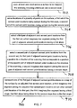
- FIG. 1 a shows the Bayes network of traditional landmark based SLAM.
- Each observation z t k is associated with a map feature m i .
- the non-divergence property is achieved since map features are observed from several locations. Correlations between map features are not considered.
- the present invention provides a method for reconstructing a map based on range measurements from a mobile platform and creating accurate maps of indoor environments.
- the method includes a novel probabilistic formulation which does not rely on data correspondences. Instead of using occupancy grid maps to represent the environment, geometric map representations and statistical prior models may be used to reconstruct maps from the data collected by a mobile robot.
- the present invention provides a method of registering multiple surface scans in a common coordinate frame and reconstructing the scanned surface at the same time.
- the invention further provides a novel probabilistic technique for solving the offline SLAM problem by jointly solving the data registration problem and the faithful reconstruction of the underlying geometry. Prior knowledge is incorporated in the map that is being constructed.
- the method of the present invention may not make this assumption.
- the measurements may be considered directly without processing them into any landmarks. It may be assumed that there is not any immediate correspondence between the measurements and the landmarks. This assumption may be quite reasonable for a number of situations. For example, a mobile robot equipped with light detection and ranging (LIDAR), which takes a finite number of measurements while it is in motion, is very unlikely to measure the exact same spot twice.
- LIDAR light detection and ranging
- each observation may create a new feature in the map. It may be assumed that there are no correspondences between observations and known features. Instead, the map prior may be used to estimate the robot's pose and the map.
- the map prior may be expressed as a probability distribution which represents a prior distribution of all measured scenes.
- An exact probabilistic model of this distribution may be infeasible and probably not even well defined.
- the present invention may focus on partial models which represent properties of the surface structure. For the optimization of the SLAM problem, a good surface prior may be very helpful.
- the observation model, the motion model, as well as the prior on the first pose may be at their equilibrium by using the measurements. This means that without any map prior, the most probable solution may be the measurement itself.
- priors may be used representing three properties: manifold priors, smoothness priors and priors for the orientation.
- the present invention may be used in the fields of robotics, mapping and 3D reconstruction. Due to the intrinsic limitations of sensor systems, spatial sensor interpretation is fundamentally an underconstrained problem. Incorporating simple priors on the environment according to the present invention enables a robot to recover better world models.
- the present invention provides a novel formulation of the SLAM problem which incorporates map priors and does not rely on the notion of landmarks.
- the invention comprises, in one form thereof, a robotic mapping method including scanning a robot across a surface to be mapped. Locations of a plurality of points on the surface are sensed during the scanning. A first of the sensed point locations is selected. A first subset of the sensed point locations that are within a vicinity of the first sensed point location is determined. A line segment that approximates the first subset of sensed point locations is ascertained. The first sensed point location is represented in a map of the surface by an adjusted first sensed point location. The adjusted first sensed point location is closer to the line segment than is the first sensed point location.
- the invention comprises, in another form thereof, a robotic mapping method including scanning a robot across a surface to be mapped. Locations of a plurality of points on the surface are sensed during the scanning. A first of the sensed point locations is selected. A preceding subset of the sensed point locations is determined. The preceding subset is disposed before the first sensed point location along a path of the scanning. A following subset of the sensed point locations is determined. The following subset is disposed after the first sensed point location along the path of the scanning. The first sensed point location is represented in a map of the surface by an adjusted first sensed point location. The adjusted first sensed point location is closer to each of the preceding and following subsets of the sensed point locations than is the first sensed point location.
- the invention comprises, in yet another form thereof, a robotic mapping method including scanning at least one robot across a surface to be mapped.
- the scanning includes a first scan and a second scan. Locations of a plurality of points on the surface are sensed. A first set of the sensed point locations are sensed during the first scan, and a second set of the sensed point locations are sensed during the second scan. A first pair of adjacent sensed point locations from the first set is selected. A first imaginary line segment joining the first pair of adjacent sensed point locations has a first slope. A second pair of adjacent sensed point locations from the second set is selected. The first pair of adjacent sensed point locations has a position in a direction of the scanning that corresponds to a position of the second pair of adjacent sensed point locations in the direction of the scanning.
- a second imaginary line segment joining the second pair of adjacent sensed point locations has a second slope.
- One of the first pair of adjacent sensed point locations is represented in a map of the surface by an adjusted first sensed point location.
- a third imaginary line segment joins the adjusted first sensed point location and an other sensed point location of the first pair.
- the third imaginary line segment has a third slope. The third slope is closer to the second slope than is the first slope.
- the invention comprises, in still another form thereof, a robotic mapping method including using a robot to sense locations of a plurality of points on a surface to be mapped.
- a first of the sensed point locations is represented in a map of the surface by an adjusted first sensed point location.
- the adjusted first sensed point location is dependent upon at least a second and a third of the sensed point locations.
- An advantage of the present invention is that it reconstructs maps that are significantly more accurate than those produced by prior art algorithms.
- the maps produced by the present invention resemble the actual structure with a much higher level of detail.
- the geometric map representations that are used yield higher accuracy and scale better than grid maps.
- the method of the invention finds maps that closely resemble the real environment.
- the inventive method is particularly superior to the prior art in cases in which no salient landmark definition is feasible.
- FIG. 1 a is a diagram illustrating a Bayes network of landmark based SLAM of the prior art.
- FIG. 1 b is a network according to one embodiment of a mapping method of the present invention.
- FIG. 2 a is a diagram illustrating one step of one embodiment of a manifold prior utilized in a mapping method of the present invention.
- FIG. 2 b is a diagram illustrating another step of the manifold prior of FIG. 2 a.
- FIG. 2 c is a diagram illustrating yet another step of the manifold prior of FIG. 2 a.
- FIG. 3 a is a diagram illustrating one step of one embodiment of a shape prior utilized in a mapping method of the present invention.
- FIG. 3 b is a diagram illustrating another step of the shape prior of FIG. 3 a.
- FIG. 3 c is a diagram illustrating yet another step of the shape prior of FIG. 3 a.
- FIG. 4 a is a diagram illustrating one step of one embodiment of an orientation prior utilized in a mapping method of the present invention.
- FIG. 4 b is a diagram illustrating another step of the orientation prior of FIG. 4 a.
- FIG. 4 c is a diagram illustrating yet another step of the orientation prior of FIG. 4 a.
- FIG. 5 is a flow chart of one embodiment of a mapping method of the present invention.
- FIG. 6 is a flow chart of another embodiment of a mapping method of the present invention.
- FIG. 7 is a flow chart of yet another embodiment of a mapping method of the present invention.
- this assumption may be accurate for a many situations.
- a mobile robot equipped with LIDAR may take a finite number of measurements or “observations” while the robot is in motion. It is very unlikely that the robot ever observes the exact same location more than once.
- the present invention has many differences from the SLAM formulations of the prior art, including:
- Equation (5) The different components of Equation (5) are now described in more detail.
- x t-1 , u t ) for the motion model can also be expressed as a Gaussian distribution
- g(u t , x t-1 ) denotes a function that models the state transition. The common model is used where the robot is assumed to perform a rotation ⁇ ⁇ ,1 followed by a translation ⁇ t , followed by another translation ⁇ ⁇ ,2 :
- this function is a linear approximation of the true motion function g g ( u t ,x t-1 ) ⁇ g ( ⁇ t , ⁇ tilde over (x) ⁇ t-1 )+ G t ( x t-1 ⁇ tilde over (x) ⁇ t-1 ) (8) at the expected pose ⁇ tilde over (x) ⁇ t-1 and with the control parameters ⁇ t .
- the Jacobian G t is the derivative of the function g
- ⁇ ⁇ ⁇ ( x ) 1 2 ⁇ ⁇ 2 ⁇ e - 1 2 ⁇ x 2 ⁇ 2 ( 16 ) and M t is the noise covariance matrix in motion space
- the standard deviation of the error may be proportional to the rotations and the translation.
- the parameters ⁇ 1 , ⁇ 2 , ⁇ 3 and ⁇ 4 are platform-specific error parameters. A better model of the actual pose after a time interval ⁇ t is thus
- the motion model may be linearized.
- the model may be decomposed into a noise-free part and a random noise component
- Equation 19 approximates Equation 18 by replacing the true motion ( ⁇ circumflex over ( ⁇ ) ⁇ ⁇ ,1 ⁇ circumflex over ( ⁇ ) ⁇ t ⁇ circumflex over ( ⁇ ) ⁇ ⁇ ,2 ) T by the measured motion ( ⁇ ⁇ ,1 ⁇ t ⁇ ⁇ ,2 ) and capturing the motion noise in an additive Gaussian with zero mean.
- the function g may be approximated through a Taylor expansion g ( u t ,x t-1 ) ⁇ g ( ⁇ t , ⁇ tilde over (x) ⁇ t-1 )+ G t ( x t-1 ⁇ tilde over (x) ⁇ t-1 ) (20)
- the motion model in Equation 19 may require the motion noise M t to be mapped into “state space.” This may once again be done by linear approximation.
- x t , m) for the observation model can also be expressed as Gaussian distribution
- h(x t , m) denotes a function that models the observation z t i .
- a beam model may be used for sensors that measure range in different directions:
- a sensor may measure the two-dimensional coordinates of a surface
- x m n ( m x m y ) , ( 29 ) where x m and y m are the true coordinates in a global coordinate system.
- the beam model approximates the physical model of range finders. Range finders measure the range r m along a beam, which originates at the local coordinate system of the sensor. The angular orientation of the sensor beam is denoted as ⁇ m
- the measurement model may be linearized.
- the function h may be approximated through a Taylor expansion
- the prior p(x 0 ) may anchor the first pose at its position (e.g., the origin of the global coordinate system).
- the prior is easily expressed by a Gaussian-type distribution
- ⁇ tilde over (x) ⁇ 0 is the initial estimate of the first pose.
- the covariance ⁇ 0 is a simple matrix with values close to zero on the diagonal and zero everywhere else.
- the probability distribution p(m) in Equation (5) represents a prior distribution of all measured scenes.
- An exact probabilistic model of this distribution may be infeasible and probably not even well defined.
- the focus of the present invention may be on partial models, which represent properties of the surface structure.
- a good surface prior may be very beneficial.
- the observation model, the motion model, as well as the prior on the first pose are at their equilibrium by using the measurements. This means that without any map prior, the most probable solution would be the measurement itself.
- the present invention uses priors representing three properties: manifold priors, smoothness priors and priors for the orientation.
- FIGS. 2-4 there are shown specific embodiments of the three different types of priors that may be utilized according to mapping methods of the present invention. More particularly, a manifold prior is illustrated in FIGS. 2 a - c ; a shape prior is illustrated in FIGS. 3 a - c ; and an orientation prior is illustrated in FIGS. 4 a - c .
- FIGS. 2-4 Each of the three priors is shown in FIGS. 2-4 as being applied to three consecutive observed readings in order to present an illustrative sample. However, it is to be understood that these priors may be applied to each available reading that has been observed. Moreover, any combination of the three types of priors may be applied to the same set of data.
- FIG. 2 a includes a number of circles A-M each of which represents a respective observation or measurement of a surface location by a robot as the robot traverses the surface. It is possible that circles A-M are the result of observations taken in a single scan or in multiples scans or trips of the robot across the surface. It is also possible that circles A-M are the result of observations taken while the robot moves at an angle, or even randomly, with respect to the surface. Thus, there may be noise in observation points A-M due to uncertainty in matching up the positions of the robot in the x-direction (i.e., in the direction across the page of FIG. 2 a ) when the robot made the observations.
- the surface may be substantially perpendicular to the page of FIG. 2 a , and the robot may be displaced from the wall in the general direction of arrow 10 .
- Each of observation points A-M may be in the same plane, as shown in FIG. 2 a .
- the map, the path of the robot, and the observations may be purely two-dimensional. That is, the offsets may be in only the x and y directions, i.e., in the plane of the page.
- FIG. 2 a more particularly illustrates an adjustment of point F, which is arbitrarily selected for purposes of the initial illustration.
- a fixed neighborhood of point F may be defined by a circle 12 having point F at the center of circle 12 .
- the radius of circle 12 may be variable within the scope of the invention, and the inventive manifold technique is not limited to use of circles of any particular radius. However, in one embodiment, there are approximately between ten and twenty points within circle 12 .
- a point's neighborhood may be defined by shapes other than circular within the scope of the invention.
- the points within the neighborhood i.e. points C, D, E, F, G, and H within circle 12 , may be used to create a best fit line 14 , such as a least squares regression line. That is, line 14 may be calculated as the line that minimizes the sum of the squares of the distances of each of points C, D, E, F, G, and H to the line.
- the distribution of points C, D, E, F, G, and H around line 14 may be modeled as a Gaussian distribution over the projected distance to the tangent line. That is, the Gaussian distribution may have its peak value at line 14 , and the distribution values may decline in directions outwardly away from (i.e., perpendicular to) line 14 .
- the most probable arrangement regarding only this manifold prior is when all points are located on the same one-dimensional manifold.
- point F may be moved closer to line 14 , and in a direction 15 perpendicular to line 14 , in the final mapping.
- the location of point F after movement may be substantially aligned with its original location in the vertical direction.
- the degree to which, or distance by which, point F is moved toward line 14 may be variable according to the invention, and the invention is not intended to be limited to any particular method of determining the amount of movement of point F toward line 14 .
- point F is moved toward line 14 by a variable amount that is governed by the Gaussian distribution.
- the closer a possible final destination is to line 14 the more likely it is that point F will actually be moved to that final destination.
- a Gaussian type manifold prior can be defined of the form:
- FIGS. 2 b and 2 c illustrate adjustments of observation points G and H, respectively, with circle 12 being re-centered on each of these points G and H.
- the details of these adjustments may be substantially similar to the adjustment of point F, and thus are not described in detail herein in order to avoid needless repetition. Illustrated in FIG. 2 c is the case wherein point H as observed happens to be located on or very near to line 14 . In this case, point H may not be adjusted, or may be adjusted only a very small distance.
- adjustments of the individual points may be performed simultaneously, i.e., at the same time, via use of a Conjugate Gradient optimizer. If another optimizer is used, such as a Stochastic Gradient Descent optimizer, adjustments of the individual points may be performed sequentially or randomly. This flexibility in the order of adjustment may be due to the adjustment of each point being performed independently of the adjustment of any other point. That is, each point may be adjusted based upon the original positions of the other points as actually observed, rather than being based upon the adjusted positions of the other points. As a specific example, point G may be adjusted in FIG.
- the above-described manifold prior models the probability that observations belong to the same surface purely based on distance.
- the shape prior in contrast, exploits the natural local smoothness of surfaces.
- the smoothness is a function of a surface's curvature. Let m i and m j be neighbors on the same surface.
- the normal on the surface patch is defined by
- n i and n ii be two adjacent normals on the surface. Then the shape prior has the form of a sub-quadratic normal distribution
- ⁇ m corresponds to a covariance matrix for smooth surfaces.
- ⁇ m is a constant, which is the integral over all other factors and therefore normalizes p m to be a probability density function.
- Sub-quadratic priors are used due to their ability to enhance features.
- the shape prior technique illustrated in FIGS. 3 a - c may model the local smoothness of natural surfaces. Two adjacent normals on a surface are more likely to be similar, thus the distance of normals is modeled as a sub-quadratic normal probabilistic distribution. The resulting distributions are indicated by the oval areas 16 in FIGS. 3 a - c . These oval-shaped distributions may have a peak values in the centers of ovals 16 , and the values may decrease in all outward directions away from the centers.
- FIG. 3 a includes a number of circles AA-GG each of which represents a respective observation or measurement of a surface location by a robot as the robot traverses the surface.
- Circles AA-GG may be the result of observations taken in a single scan or trip of the robot across the surface.
- observation points AA-GG may not have the noise in their locations that may result from being sensed in multiple scans.
- the surface may be substantially perpendicular to the page of FIG. 3 a , and the robot may be displaced from the wall in the general direction of arrow 10 .
- Each of observation points AA-GG may be in the same plane, as shown in FIG. 3 a .
- the map, the path of the robot, and the observations may be purely two-dimensional. That is, the offsets may be in only the x and y directions, i.e., in the plane of the page.
- FIG. 3 a more particularly illustrates an adjustment of point CC, which is arbitrarily selected for purposes of the initial illustration.
- Point CC may be moved in a direction 17 generally toward a line 18 joining the two adjacent observation points BB and DD.
- the degree to which, or distance by which, point CC is moved toward line 18 may be variable according to the invention, and the invention is not intended to be limited to any particular method of determining the amount of movement of point CC toward line 18 .
- point CC is moved toward line 18 by a variable amount that is governed by the sub-quadratic normal distribution represented by oval 16 and having peak values near line 18 .
- the closer a possible final destination is to line 18 the more likely it is that point CC will actually be moved to that final destination.
- the greater the distance between point CC and line 18 the slower the drop off in distribution values away from line 18 may be. That is, the greater the distance between point CC and line 18 , the flatter the distribution represented by oval 16 .
- FIGS. 3 b and 3 c illustrate adjustments of observation points DD and EE, respectively, with respective oval distributions 16 being disposed between adjacent points CC and EE in FIG. 3 b , and between adjacent points DD and FF in FIG. 3 c .
- the details of these adjustments may be substantially similar to the adjustment of point CC, and thus are not described in detail herein in order to avoid needless repetition.
- adjustments of the individual points may be performed simultaneously, i.e., at the same time, via use of a Conjugate Gradient optimizer. If another optimizer is used, such as a Stochastic Gradient Descent optimizer, adjustments of the individual points may be performed sequentially or randomly. This flexibility in the order of adjustment may be due to the adjustment of each point being performed independently of the adjustment of any other point. That is, each point may be adjusted based upon the original positions of the other points as actually observed, rather than being based upon the adjusted positions of the other points. As specific examples, point DD may be adjusted in FIG.
- point EE may be adjusted in FIG. 3 c based upon point DD's original, unadjusted position in FIGS. 3 a and 3 b .
- adjustment of each point based upon the original positions of the other points may occur within only one iteration of the optimization. Once all points are adjusted, the new, adjusted positions may be used as inputs for the next iteration.
- the shape prior is affected more by local or nearby measurements. That is, the shape prior sub-quadratic normal distribution may be defined by only the two closest points, while the manifold prior Gaussian distribution may be defined by a greater number of points existing in the neighborhood of the point being adjusted.
- the third prior that may be used according to the present invention is directed to the orientation of adjacent surface patches. If two surface patches such as the ones shown in each of FIGS. 4 a - c belong to the same physical surface, then the orientation of edges representing the same portion may have a similar orientation. Once again this can be modeled as a probability distribution as follows: Let n i and n j be two corresponding normals on two surface patches. Then the orientation prior has the form of a quadratic normal distribution
- ⁇ 0 corresponds to a covariance matrix for the orientation of adjacent surfaces.
- ⁇ 0 is a constant, which is the integral over all other factors and therefore normalizes p 0 to be a probability density function.
- the resulting probability density function is represented by oval areas 20 in FIGS. 4 a - c.
- the orientation prior illustrated in FIGS. 4 a - c uses the orientation of adjacent surface patches.
- the differences between two corresponding normals are modeled as quadratic normal distributions.
- the resulting distributions are indicated by the oval areas 20 in FIGS. 4 a - c .
- These oval-shaped distributions may have a peak values in the centers of ovals 20 , and the values may decrease in all outward directions away from the centers.
- FIG. 4 a includes a first set of circles A 1 -G 1 each of which represents a respective observation or measurement of a surface location by a robot as the robot traverses the surface in a first scan in a direction generally across the page of FIG. 4 a .
- FIG. 4 a also includes a second set of circles A 2 -F 2 each of which represents a respective observation or measurement of a surface location by a robot as the robot traverses the surface in a second scan in a direction generally from the left-hand side to the right-hand side in FIG. 4 a .
- observation points A 1 -G 1 and A 2 -F 2 may not have the noise in their locations that may result from being sensed in multiple scans.
- the surface may be substantially perpendicular to the page of FIG. 4 a , and the robot may be displaced from the wall in the general direction of arrow 10 .
- the respective strips of surface area that are scanned to produce respective sets of observation points A 1 -G 1 and A 2 -F 2 may be effectively the same strip of surface area. However, it is possible that the sets of observation points A 1 -G 1 and A 2 -F 2 are offset relative to each other in the x-direction across the page of FIG. 4 a.
- the two sets of observation points A 1 -G 1 and A 2 -F 2 are shown in each of FIGS. 4 a - c as being separated from each other by an arbitrary distance in the y-direction. However, for purposes of the orientation prior technique, this separation distance in the y-direction is of no consequence.
- the angular orientation between the two sets of observation points A 1 -G 1 and A r F 2 does affect the operation of the orientation prior technique.
- the angular orientation between the two sets of observation points A 1 -G 1 and A 2 -F 2 may be established by any method within the scope of the invention (e.g., by a least squares method).
- the angular orientation between the two sets of observation points A 1 -G 1 and A 2 -F 2 once established may be held constant for the adjustment of each observation point. That is, although the first set of observation points A 1 -G 1 is illustrated with different angular orientations in each of FIGS. 4 a - c , and likewise the second set of observation points A 2 -F 2 is illustrated with different angular orientations in each of FIGS. 4 a - c , the orientation of the first set of observation points A 1 -G 1 relative to the orientation of the second set of observation points A 2 -F 2 may be held constant in each of FIGS. 4 a - c and for each point adjustment.
- Each of observation points A 1 -G 1 and A 2 -F 2 may be in the same plane, as shown in FIG. 4 a .
- the map, the path of the robot, and the observations may be purely two-dimensional. That is, the offsets may be in only the x and y directions, i.e., in the plane of the page.
- FIG. 4 a more particularly illustrates an adjustment of point C 1 , which is arbitrarily selected for purposes of the initial illustration.
- An adjustment of point C 1 may include selecting a line segment of the second set of observation points A 2 -F 2 that corresponds to the line segment that joins points B 1 and C 1 .
- the scope of the invention may encompass any method of selecting such a corresponding line segment.
- the corresponding line segment may be selected as one that has the closest position to the first line segment in the x-direction.
- the line segment joining points B 2 and C 2 is selected as the line segment corresponding to the line segment that joins points B 1 and C I .
- an imaginary line 21 that intersects point B 1 and that is parallel to the line segment joining points B 2 and C 2 is determined.
- point C 1 may be moved toward line 21 in a direction 22 that is generally perpendicular to the line segment joining observation points B 1 and C 1 .
- the degree to which, or distance by which, point C 1 is moved toward line 21 may be variable according to the invention, and the invention is not intended to be limited to any particular method of determining the amount of movement of point C 1 toward line 21 . In a specific embodiment, however, point C 1 is moved toward line 21 by a variable amount that is governed by the quadratic normal distribution represented by oval 20 and having peak values near line 21 .
- FIGS. 4 b and 4 c illustrate adjustments of observation points D 1 and E 1 , respectively, with respective oval distributions 20 being oriented substantially perpendicular to the line segment that ends at the point being adjusted, and also being centered on line 21 .
- the details of these adjustments may be substantially similar to the adjustment of point C 1 , and thus are not described in detail herein in order to avoid needless repetition.
- one set may include a greater number of points, and consequently a greater number of line segments, than the other set. If the set being adjusted includes more points and line segments, then at least one line segment in the other set may necessarily serve as a corresponding line segment to more than one line segment in the first set.
- the line segment joining points B 2 and F 2 may correspond to both the line segment joining points E 1 and F 1 and the line segment joining points F 1 and G 1 .
- the set being adjusted includes fewer points and line segments, then at least one line segment in the other set may not serve as a corresponding line segment to any line segment in the first set.
- the second set of observation points may also be adjusted based upon the first set of observation points. More particularly, the second set of observation points may be adjusted based upon the first set of points as the first set of points were observed before their adjustment.
- Equation (5) is defined a novel probabilistic model for the SLAM problem, and hereinabove are described the different components for this model.
- the problem is defined as finding the maximum a-posteriori solution (MAP) of Equation (5). Described hereinbelow is a practical implementation to calculate this solution.
- the algorithm of the present invention consists of three main parts: first the motion model and the observation model from Equations (7) and (27), respectively, are used to calculate an initial estimate for x 1:t and m 1:i . Next, a preconditioning is applied to improve this estimate. Finally, a non-linear conjugate gradient variant is used to find the parameters which minimize E(x 0:t , m). An outline of this algorithm is presented below as Algorithm 1.
- objective function E(x 0:t , m) is unfortunately non-linear and thus finding the global minimum may be difficult.
- the approach of the present invention is to use a simple scan alignment algorithm prior to the optimization.
- the “iterative-closest-point” (ICP) algorithm is used to create an initial alignment and therefore a better staring point for the optimization.
- ICP iterative-closest-point
- Finding the most probable solution and therefore the most probable path and the most probable map is the task of finding the global minimum of the function E(x 1:t , m). This minimization results in high dimensional, sparse optimization problem.
- the Nonlinear Conjugate Gradient Method (CG) of optimization may help to find a good solution.
- CG Nonlinear Conjugate Gradient Method
- a Newton-Raphson line search and the Fletcher-Reeves formulation may be used to linearly combine the negative gradient of the function E(x 0:t , m) with previous such gradients. In every iteration of CG, the prior model is rebuilt to ensure the best model is always used at each iteration.
- Algorithm 1 A more detailed outline is presented in Algorithm 1 above.
- a robotic mapping method 500 of the present invention is illustrated in FIG. 5 .
- a robot is scanned across a surface to be mapped.
- a robot may scan a surface while moving substantially parallel to the surface, while moving at an angle relative to the surface, or while moving in random directions.
- a second step 504 locations of a plurality of points on the surface are sensed, the sensing occurring during the scanning.
- the robot may sense location points A-M in FIG. 2 a while scanning.
- a first sensed point location is selected.
- sensed point location F is selected in FIG. 2 a .
- locations G and H are selected in FIGS. 2 b and 2 c , respectively.
- a first subset of the sensed point locations that are within a vicinity of the first sensed point location are determined. For example, in FIG. 2 a , sensed point locations C, D, E and G, H that are within a circle 12 having point location F at the center are determined.
- a vicinity is not restricted to an area of a certain size within the scope of the invention.
- a vicinity of a first sensed point location may be defined as a certain number of other sensed point locations immediately preceding and/or following the first sensed point location.
- step 510 a line segment that approximates the first subset of sensed point locations is ascertained.
- line segment 14 is ascertained by the least squares method.
- the first sensed point location is represented in a map of the surface by an adjusted first sensed point location, the adjusted first sensed point location being closer to the line segment than is the first sensed point location.
- sensed point location F may be represented in a surface map by an adjusted location that is closer to line segment 14 than is location F, and that is positioned approximately along arrow 15 in FIG. 2 a.
- FIG. 6 Another embodiment of a robotic mapping method 600 of the present invention is illustrated in FIG. 6 .
- a robot is scanned across a surface to be mapped.
- a robot may scan a surface from the left-hand side to the right-hand side of FIG. 3 a.
- a second step 604 locations of a plurality of points on the surface are sensed, the sensing occurring during the scanning.
- the robot may sense location points AA-GG in FIG. 3 a while scanning.
- a first sensed point location is selected.
- sensed point location CC is selected in FIG. 3 a .
- locations DD and EE are selected in FIGS. 3 b and 3 c , respectively.
- a preceding subset of the sensed point locations is determined, the preceding subset being disposed before the first sensed point location along a path of the scanning.
- the preceding subset includes only a single sensed point location BB.
- Point location BB is disposed before point location CC along the left to right scanning path in FIG. 3 a .
- the preceding subset it is possible within the scope of the invention for the preceding subset to include a plurality of sensed point locations, such as both BB and CC, for example.
- a following subset of the sensed point locations is determined, the following subset being disposed after the first sensed point location along the path of the scanning.
- the following subset includes only a single sensed point location DD.
- Point location DD is disposed after point location CC along the left to right scanning path in FIG. 3 a .
- the following subset it is possible within the scope of the invention for the following subset to include a plurality of sensed point locations, such as point locations DD, EE and FF, for example.
- the first sensed point location is represented in a map of the surface by an adjusted first sensed point location, the adjusted first sensed point location being closer to each of the preceding and following subsets of the sensed point locations than is the first sensed point location.
- sensed point location CC may be represented in a surface map by an adjusted location that is closer to line segment 18 than is location CC, and that is positioned approximately along arrow 17 in FIG. 3 a.
- FIG. 7 Another embodiment of a robotic mapping method 700 of the present invention is illustrated in FIG. 7 .
- a first step 702 at least one robot is scanned across a surface to be mapped, the scanning including a first scan and a second scan.
- the scanning includes a first scan and a second scan, and these scans may be performed by the same robot or by different robots.
- a second step 704 locations of a plurality of points on the surface are sensed, a first set of the sensed point locations being sensed during the first scan, a second set of the sensed point locations being sensed during the second scan.
- a first set of sensed point locations A 1 -G 1 are sensed during a first scan
- a second set of sensed point locations A 2 -F 2 are sensed during a second scan.
- a first pair of adjacent sensed point locations are selected from the first set, a first imaginary line segment joining the first pair of adjacent sensed point locations having a first slope. That is, adjacent sensed point locations B 1 and C 1 are selected from the first set.
- An imaginary line segment joining point locations B 1 and C 1 is shown in FIG. 4 a , and this line segment appears to have a slope of approximately 0.5 in the viewpoint of FIG. 4 a.
- a second pair of adjacent sensed point locations is selected from the second set, the first pair of adjacent sensed point locations having a position in a direction of the scanning that corresponds to a position of the second pair of adjacent sensed point locations in the direction of the scanning, a second imaginary line segment joining the second pair of adjacent sensed point locations having a second slope.
- a second pair of adjacent sensed point locations B 2 and C 2 are selected from the second set.
- the first pair of adjacent sensed point locations B 1 and C 1 have a position in a direction of the scanning (i.e., in the left to right direction) that corresponds to a position of the second pair of adjacent sensed point locations B 2 and C 2 in the direction of the scanning. That is, locations B 1 and C 1 may be approximately horizontally aligned with locations B 2 and C 2 . Stated another way, locations B 1 and C 1 are relatively close to locations B 2 and C 2 .
- a second imaginary line segment joins the second pair of adjacent sensed point locations B 2 and C 2 , as shown in FIG. 4 a . This line segment joining point locations B 2 and C 2 has a slope of approximately zero. That is, the line segment joining point locations B 2 and C 2 is approximately horizontal in the viewpoint of FIG. 4 a.
- one of the first pair of adjacent sensed point locations is represented in a map of the surface by an adjusted first sensed point location, a third imaginary line segment joining the adjusted first sensed point location and an other sensed point location of the first pair, the third imaginary line segment having a third slope, the third slope being closer to the second slope than is the first slope.
- point location C 1 is represented in a map of the surface by an adjusted location that is closer to the line segment joining points B 2 and C 2 than is location C 1 and is positioned approximately along arrow 22 in FIG. 4 a .
- a third imaginary line segment may join the adjusted first sensed point location and sensed point location B 1 .
- This third imaginary line segment has a slope that is closer to the slope of the line segment joining points B 2 and C 2 than is the slope of the line segment joining points B 1 and C 1 .
- This third imaginary line segment has a slope that is closer to the zero slope of the line segment joining points B 2 and C 2 (i.e., flatter) than is the slope of the line segment joining points B 1 and C 1 .
- the present invention has been described herein primarily in connection with mapping in planar environments with two-dimensional maps and poses to be estimated. However, it is to be understood that the present invention is equally applicable to two-dimensional maps and poses to be estimated.
Landscapes
- Engineering & Computer Science (AREA)
- Physics & Mathematics (AREA)
- General Physics & Mathematics (AREA)
- Radar, Positioning & Navigation (AREA)
- Theoretical Computer Science (AREA)
- Mathematical Optimization (AREA)
- Mathematical Physics (AREA)
- Evolutionary Computation (AREA)
- Computational Mathematics (AREA)
- Mathematical Analysis (AREA)
- Artificial Intelligence (AREA)
- Pure & Applied Mathematics (AREA)
- Computing Systems (AREA)
- General Engineering & Computer Science (AREA)
- Data Mining & Analysis (AREA)
- Software Systems (AREA)
- Algebra (AREA)
- Probability & Statistics with Applications (AREA)
- Aviation & Aerospace Engineering (AREA)
- Remote Sensing (AREA)
- Automation & Control Theory (AREA)
- Control Of Position, Course, Altitude, Or Attitude Of Moving Bodies (AREA)
Abstract
Description
-
- xt: A vector describing the position and orientation of the robot.
- ut: The control vector that was applied at time t−1 and carries information about the change of the robot's pose.
- zt k: The observations taken from the robot of the kth feature.
- ct k: A correspondence variable between the kth feature and the ith landmark.
- m: A vector of features m={mi} representing the environment around the robot.
p(x t ,m|u 1:t ,z 1:t ,c 1:t) (1)
It involves estimating the posterior over the momentary pose xt along with the map m. It is called “online” because it involves only estimating quantities at the time t. In contrast, the “full SLAM problem” seeks to calculate a posterior over all quantities:
p(x 1:t ,m|u 1:t ,z 1:t ,c 1:t) (2)
The full SLAM problem is focused on herein in order to simplify the further discussion. A closed form expression of Equation (2) can be obtained by recursively applying Bayes' Rule and subsequent induction over t:
p(x 1:t ,m|u 1:t ,z 1:t ,c 1:t)=ηp(x 0)p(m)Πt [p(x t |x t-1 ,u t)Πp(z t i |x t ,m,c t i)] (3)
Here p(xt|xt-1, ut) is known as the “motion model” which describes state transitions of the robot's pose in terms of a probability distribution. The state transitions are assumed to be a Markov process and independent of both the observations and the map. The term p(zt i|xt, m, ct i) on the other hand denotes an “observation model” which models an observation zt i from a known pose and a known map as a probability distribution. Both models have been studied well for a variety of robots and sensors. The two prior terms p(x0) and p(m) characterize priors about the first robot pose and about the map, respectively. Usually p(x0) is used to anchor the initial pose to a fixed location. The map prior p(m) is typically assumed to be unknown and subsumed into the normalizer η. The process of finding the most probable solution to the full SLAM problem is simply the process of finding the set of poses {circumflex over (x)}1:t and the map {circumflex over (m)} that maximizes the posterior probability of Equation (3).
A graphical model of this formulation is illustrated in
-
- Each observation zt k creates a new feature in the map.
- No correspondence is assumed between observations and known features.
- Instead, the map prior p(m) is used to estimate the robot's pose and the map.
The new posterior for this formulation is:
p(x 1:t ,m|u 1:t ,z 1:t)=ηp(x 0)p(m)Πt [p(x t |x t-1 ,u t)Πi p(z t i |x t ,m)] (5)
A graphical model of this formulation is illustrated inFIG. 1 b which shows the network according to a method of the present invention. In contrast to the prior art method depicted inFIG. 1 a, it is not assumed that map features are observed from different locations. Instead, the correlations between features are used to achieve a non-divergence property.
Here g(ut, xt-1) denotes a function that models the state transition. The common model is used where the robot is assumed to perform a rotation δφ,1 followed by a translation δt, followed by another translation δφ,2:
In this case, this function is a linear approximation of the true motion function
g(u t ,x t-1)≈
at the expected pose {tilde over (x)}t-1 and with the control parameters ũt. The Jacobian Gt is the derivative of the function
is represented by a concatenation of three basic motions: a rotation δφ,1, a straight-line motion δt, and another rotation δφ,2
δφ,1 =a tan 2(δy−δx) (10)
δt=√{square root over (δx 2+δy 2)} (11)
δφ,2=δθ−δφ,1 (12)
Consequently, the true position after one timestamp Δt can be obtained by
In actuality, real platform motion is subject to noise. The values of the rotations and the translation are disturbed by independent noise. According to the invention, this noise may be modeled by a zero-centered random variable with finite variance. It may be assumed that the actual incremental travel distances are given by
Here εσ is a zero-mean, normal distributed error variable with standard deviation σ.
and Mt is the noise covariance matrix in motion space
Equation 19 approximates
g(u t ,x t-1)≈g(ũ t ,{tilde over (x)} t-1)+G t(x t-1 −{tilde over (x)} t-1) (20)
The Jacobian Gt is the derivative of the function g with respect to xt-1 at the expected pose {tilde over (x)}t-1=({tilde over (x)} {tilde over (y)} {tilde over (θ)})T and with the expected motion parameters ũt ({circumflex over (δ)}φ,i {circumflex over (δ)}t {circumflex over (δ)}φ,2)T
Finally, the approximate mapping between the motion noise in motion space to the motion noise in state space is derived by the multiplication
R t =v t M t V t T. (25)
wherein h(xt, m) denotes a function that models the observation zt i. A beam model may be used for sensors that measure range in different directions:
Again, this function is a linear approximation of the true measurement function
at the expected pose {tilde over (x)}t and observing the expected feature {tilde over (m)}i. The Jacobian Ht,i is the derivative of the function
where xm and ym are the true coordinates in a global coordinate system. The beam model approximates the physical model of range finders. Range finders measure the range rm along a beam, which originates at the local coordinate system of the sensor. The angular orientation of the sensor beam is denoted as θm
The endpoint of this measurement is mapped into the global coordinate system via the trigonometric transformation
where xt=(x y θ)T denotes the pose of the sensing platform in global coordinates.
and Qt is the noise covariance matrix in “measurement space”
A better model of the actual measurement is thus
The Jacobian Ht is the derivative of the function h with respect to xt at the current pose estimate {tilde over (x)}t=({tilde over (x)} {tilde over (y)} {tilde over (θ)})T and the surface estimate {tilde over (m)}t=({tilde over (m)}x {tilde over (m)}y)T
with q={circumflex over (δ)}x 2+{circumflex over (δ)}y 2, {circumflex over (δ)}x={tilde over (m)}x−{tilde over (x)}, and {circumflex over (δ)}y={tilde over (m)}y−{tilde over (y)}.
p(m)=p m(m)p s(m)p o(m) (41)
The independence assumption is most likely not true and is a good starting point for further improvements. It has been found empirically that even though this assumption is violated, the method of the present invention yields good results.
d i=(m i −o i)·n i. (42)
wherein point oi is the point at which the normal ni begins on
where σm is the variance of tangent line distances and ηm=Πi(σm√{square root over (2π)})−1 is a normalizer which subsumes all constant factors.
Here Ωm corresponds to a covariance matrix for smooth surfaces. Again ηm is a constant, which is the integral over all other factors and therefore normalizes pm to be a probability density function. Sub-quadratic priors are used due to their ability to enhance features.
Here Ω0 corresponds to a covariance matrix for the orientation of adjacent surfaces. Again η0 is a constant, which is the integral over all other factors and therefore normalizes p0 to be a probability density function. The resulting probability density function is represented by
| |
| 1: for all constrols ut do | ||
| 2: xt ← motion_model (ut, xt−1) | ||
| 3: for all observations zt i do | ||
| 4: mi ← observation_model (xt, zt i) | ||
| 5: end for | ||
| 6: end for | ||
| 7: x1:t, m1:i ← iterative_closest_point (x1:t, m1:i) | ||
| 8: y0 = ( x1:t m1:i )T | ||
| 9: repeat | ||
| 10: create prior model p(m) | ||
| 11: find an αi that minimizes E(yi + αidi) | ||
| 12: update the state vector yi+1 = yi + αidi | ||
| 13: calculate the new residual ri+1 = −∇ E(yi+1) | ||
| 14: calculate βi+1 FR = (ri+1 Tri+1)/(ri Tri) (Fletcher-Reeves method) | ||
| 15: calculate the new search direction di+1 = ri+1 + βi+1 |
||
| 16. until convergence | ||
Claims (20)
Priority Applications (1)
| Application Number | Priority Date | Filing Date | Title |
|---|---|---|---|
| US13/666,910 US8831778B2 (en) | 2009-04-24 | 2012-11-01 | Method of accurate mapping with mobile robots |
Applications Claiming Priority (2)
| Application Number | Priority Date | Filing Date | Title |
|---|---|---|---|
| US12/429,425 US8340818B2 (en) | 2009-04-24 | 2009-04-24 | Method of accurate mapping with mobile robots |
| US13/666,910 US8831778B2 (en) | 2009-04-24 | 2012-11-01 | Method of accurate mapping with mobile robots |
Related Parent Applications (1)
| Application Number | Title | Priority Date | Filing Date |
|---|---|---|---|
| US12/429,425 Continuation US8340818B2 (en) | 2009-04-24 | 2009-04-24 | Method of accurate mapping with mobile robots |
Publications (2)
| Publication Number | Publication Date |
|---|---|
| US20130060382A1 US20130060382A1 (en) | 2013-03-07 |
| US8831778B2 true US8831778B2 (en) | 2014-09-09 |
Family
ID=42992823
Family Applications (2)
| Application Number | Title | Priority Date | Filing Date |
|---|---|---|---|
| US12/429,425 Active 2031-06-26 US8340818B2 (en) | 2009-04-24 | 2009-04-24 | Method of accurate mapping with mobile robots |
| US13/666,910 Active 2029-08-28 US8831778B2 (en) | 2009-04-24 | 2012-11-01 | Method of accurate mapping with mobile robots |
Family Applications Before (1)
| Application Number | Title | Priority Date | Filing Date |
|---|---|---|---|
| US12/429,425 Active 2031-06-26 US8340818B2 (en) | 2009-04-24 | 2009-04-24 | Method of accurate mapping with mobile robots |
Country Status (1)
| Country | Link |
|---|---|
| US (2) | US8340818B2 (en) |
Cited By (3)
| Publication number | Priority date | Publication date | Assignee | Title |
|---|---|---|---|---|
| US20140052296A1 (en) * | 2012-08-16 | 2014-02-20 | Samsung Techwin Co., Ltd. | Robot system and method for driving the same |
| US9943959B2 (en) | 2016-04-25 | 2018-04-17 | Disney Enterprises, Inc. | Map localizing with partially obstructed ranging devices for autonomous robots and vehicles |
| CN113966264A (en) * | 2019-05-17 | 2022-01-21 | 西门子股份公司 | Method, computer program product and robot control device for positioning an object that is movable during manipulation by a robot on the basis of contact, and robot |
Families Citing this family (20)
| Publication number | Priority date | Publication date | Assignee | Title |
|---|---|---|---|---|
| US8930023B2 (en) | 2009-11-06 | 2015-01-06 | Irobot Corporation | Localization by learning of wave-signal distributions |
| US20120195491A1 (en) * | 2010-07-21 | 2012-08-02 | Palo Alto Research Center Incorporated | System And Method For Real-Time Mapping Of An Indoor Environment Using Mobile Robots With Limited Sensing |
| EP2619742B1 (en) * | 2010-09-24 | 2018-02-28 | iRobot Corporation | Systems and methods for vslam optimization |
| EP2511656A1 (en) * | 2011-04-14 | 2012-10-17 | Hexagon Technology Center GmbH | Measuring system for determining the 3D coordinates of an object surface |
| US8798840B2 (en) * | 2011-09-30 | 2014-08-05 | Irobot Corporation | Adaptive mapping with spatial summaries of sensor data |
| US9741140B2 (en) | 2014-05-19 | 2017-08-22 | Microsoft Technology Licensing, Llc | Fast solving for loop closure using a relative state space |
| US20160203199A1 (en) * | 2015-01-12 | 2016-07-14 | Point Inside, Inc. | Location coordinate conversion service, method and system |
| US9990448B2 (en) | 2015-03-17 | 2018-06-05 | Ca, Inc. | Data center floor plan mapping using location-aware device |
| DE102015003666A1 (en) * | 2015-03-20 | 2016-09-22 | Daimler Ag | Method for processing acquired measured data of a sensor |
| CN105115490A (en) * | 2015-07-16 | 2015-12-02 | 深圳前海达闼科技有限公司 | Method for determining indoor active area, and apparatus thereof |
| RU2678960C1 (en) * | 2015-08-28 | 2019-02-04 | Ниссан Мотор Ко., Лтд. | Device for estimating vehicle position, method for estimating vehicle position |
| US10209063B2 (en) * | 2015-10-03 | 2019-02-19 | X Development Llc | Using sensor-based observations of agents in an environment to estimate the pose of an object in the environment and to estimate an uncertainty measure for the pose |
| US10349035B2 (en) * | 2015-11-16 | 2019-07-09 | Abb Schweiz Ag | Automatically scanning and representing an environment having a plurality of features |
| US11353326B2 (en) * | 2016-03-06 | 2022-06-07 | Arizona Board Of Regents On Behalf Of The University Of Arizona | Traverse and trajectory optimization and multi-purpose tracking |
| DE102016011378A1 (en) | 2016-09-21 | 2017-04-13 | Daimler Ag | Method for self-localization of a vehicle |
| RU2017133806A (en) * | 2017-09-28 | 2019-03-28 | Акционерное общество "НЕОЛАНТ" | METHOD OF DATA COLLECTION AND SYSTEM FOR IMPLEMENTING THE INDICATED METHOD |
| US11441890B2 (en) * | 2019-09-20 | 2022-09-13 | Nec Corporation | Linear-grammetry and calibration by simultaneous multilateration using only edge distance estimates through two-way ranging |
| EP3955082B1 (en) | 2020-08-12 | 2024-07-17 | Robert Bosch GmbH | Computer-implemented method and device for controlling a mobile robot based on semantic environment maps |
| US20240329641A1 (en) * | 2023-03-31 | 2024-10-03 | Omron Corporation | Systems and methods for map transformation between mobile robots |
| CN120494763B (en) * | 2025-07-16 | 2025-09-30 | 南京众集思信息技术有限公司 | Engineering project regional mapping method and system |
Family Cites Families (36)
| Publication number | Priority date | Publication date | Assignee | Title |
|---|---|---|---|---|
| US941940A (en) * | 1908-10-07 | 1909-11-30 | James Scott Mccormick | Revolving safe. |
| US1759129A (en) * | 1928-02-16 | 1930-05-20 | O B Mcclintock Company | After-hour depository |
| US2081271A (en) * | 1934-02-02 | 1937-05-25 | Duplex Electric Company | Vault protective system |
| US2624650A (en) * | 1950-02-27 | 1953-01-06 | Perales Marta Perez De | File cabinet |
| US3927923A (en) * | 1972-07-28 | 1975-12-23 | Ray D Kimmel | Gun rack |
| US3762789A (en) * | 1972-08-22 | 1973-10-02 | K Robertson | Burgler proof gun apparatus |
| USD252430S (en) * | 1977-05-20 | 1979-07-24 | Eco Industries, Inc. | Gun cabinet |
| US4099808A (en) * | 1977-08-08 | 1978-07-11 | Eco Industries, Inc. | Upright vault-like steel cabinet for guns and valuables |
| USD260710S (en) * | 1979-05-01 | 1981-09-15 | Miller Arlie D | Gun cabinet |
| US4244302A (en) * | 1979-09-18 | 1981-01-13 | Automatic Devices Company | Door mounting and operating apparatus for security transaction enclosures and the like |
| US5006988A (en) * | 1989-04-28 | 1991-04-09 | University Of Michigan | Obstacle-avoiding navigation system |
| US5111401A (en) * | 1990-05-19 | 1992-05-05 | The United States Of America As Represented By The Secretary Of The Navy | Navigational control system for an autonomous vehicle |
| USD335595S (en) * | 1991-06-24 | 1993-05-18 | Bowen Garry R | Rotary rifle cabinet |
| USD348576S (en) * | 1993-01-22 | 1994-07-12 | Narramore Jerry C | Gun cabinet |
| IT1271241B (en) * | 1994-10-04 | 1997-05-27 | Consorzio Telerobot | NAVIGATION SYSTEM FOR AUTONOMOUS MOBILE ROBOT |
| ATE185006T1 (en) * | 1996-03-06 | 1999-10-15 | Gmd Gmbh | AUTONOMOUS MOBILE ROBOT SYSTEM FOR SENSOR AND CARD-BASED NAVIGATION IN A LINE NETWORK |
| DE59701408D1 (en) * | 1996-07-02 | 2000-05-11 | Siemens Ag | METHOD FOR CREATING A CELLULAR STRUCTURED ENVIRONMENTAL MAP FROM A SELF-MOBILE MOBILE UNIT ORIENTED IN THE ENVIRONMENT WITH AID WITH WAVE REFLECTION-BASED SENSORS |
| USD408174S (en) * | 1998-01-21 | 1999-04-20 | Jahabow Industries, Inc. | Rifle display cabinet |
| JP2000292538A (en) * | 1999-04-07 | 2000-10-20 | Mitsubishi Electric Corp | Obstacle detection device for vehicles |
| US6314341B1 (en) * | 1999-11-26 | 2001-11-06 | Yutaka John Kanayama | Method of recording trajectory data and sensor data for a manually-driven vehicle |
| JP4159794B2 (en) * | 2001-05-02 | 2008-10-01 | 本田技研工業株式会社 | Image processing apparatus and method |
| US7089162B2 (en) * | 2001-11-07 | 2006-08-08 | Harman International Industries, Incorporated | Navigation map creation system |
| USD462517S1 (en) * | 2001-11-07 | 2002-09-10 | Mag-Nif Incorporated | Key holder |
| DE10156257A1 (en) * | 2001-11-09 | 2003-05-28 | Bosch Gmbh Robert | Micromechanical resonator |
| US6522288B1 (en) * | 2002-01-09 | 2003-02-18 | M/A-Com, Inc. | Method and apparatus for determining location of objects based on range readings from multiple sensors |
| US20030141794A1 (en) * | 2002-01-30 | 2003-07-31 | Cleveland Terri Peartree | Fire-resistant gun cabinet |
| US6865993B2 (en) * | 2002-04-08 | 2005-03-15 | David Warren Bartel | Safe |
| US6868975B2 (en) * | 2002-04-17 | 2005-03-22 | Rex R. Sells | Revolving gun safety cabinet |
| US6922632B2 (en) * | 2002-08-09 | 2005-07-26 | Intersense, Inc. | Tracking, auto-calibration, and map-building system |
| US7272467B2 (en) * | 2002-12-17 | 2007-09-18 | Evolution Robotics, Inc. | Systems and methods for filtering potentially unreliable visual data for visual simultaneous localization and mapping |
| US7689321B2 (en) * | 2004-02-13 | 2010-03-30 | Evolution Robotics, Inc. | Robust sensor fusion for mapping and localization in a simultaneous localization and mapping (SLAM) system |
| US20080045914A1 (en) * | 2006-06-08 | 2008-02-21 | Zoltan Egeresi | Diaper shredder, liquefier disposal |
| US7587260B2 (en) * | 2006-07-05 | 2009-09-08 | Battelle Energy Alliance, Llc | Autonomous navigation system and method |
| US8474923B2 (en) * | 2007-03-22 | 2013-07-02 | Pendleton Safe Company | Safes with rotating inner supports |
| USD586525S1 (en) * | 2008-08-12 | 2009-02-10 | Bruce Pendleton | Safe |
| KR101021105B1 (en) * | 2008-09-11 | 2011-03-15 | 포항공과대학교 산학협력단 | Maximum Approximate Likelihood Method with Conflict Elimination for Mapping Robot Using Ultrasonic Sensors |
-
2009
- 2009-04-24 US US12/429,425 patent/US8340818B2/en active Active
-
2012
- 2012-11-01 US US13/666,910 patent/US8831778B2/en active Active
Cited By (6)
| Publication number | Priority date | Publication date | Assignee | Title |
|---|---|---|---|---|
| US20140052296A1 (en) * | 2012-08-16 | 2014-02-20 | Samsung Techwin Co., Ltd. | Robot system and method for driving the same |
| US9126338B2 (en) * | 2012-08-16 | 2015-09-08 | Hanwha Techwin Co., Ltd. | Robot system and method for driving the same |
| US9943959B2 (en) | 2016-04-25 | 2018-04-17 | Disney Enterprises, Inc. | Map localizing with partially obstructed ranging devices for autonomous robots and vehicles |
| CN113966264A (en) * | 2019-05-17 | 2022-01-21 | 西门子股份公司 | Method, computer program product and robot control device for positioning an object that is movable during manipulation by a robot on the basis of contact, and robot |
| US20220226991A1 (en) * | 2019-05-17 | 2022-07-21 | Siemens Aktiengesellschaft | Method, computer program product and robot control system for the contact-based localization of objects that can be moved when manipulated by robot, and robot |
| US12076865B2 (en) * | 2019-05-17 | 2024-09-03 | Siemens Aktiengesellschaft | Method, computer program product and robot control system for the contact-based localization of objects that can be moved when manipulated by robot, and robot |
Also Published As
| Publication number | Publication date |
|---|---|
| US20100274387A1 (en) | 2010-10-28 |
| US8340818B2 (en) | 2012-12-25 |
| US20130060382A1 (en) | 2013-03-07 |
Similar Documents
| Publication | Publication Date | Title |
|---|---|---|
| US8831778B2 (en) | Method of accurate mapping with mobile robots | |
| Jiao et al. | Robust odometry and mapping for multi-lidar systems with online extrinsic calibration | |
| US11988781B2 (en) | Extrinsic calibration method of multiple 3D LiDAR sensors for autonomous navigation system | |
| Nieto et al. | Recursive scan-matching SLAM | |
| Kümmerle et al. | Large scale graph-based SLAM using aerial images as prior information | |
| US8121399B2 (en) | Self-position identifying method and device, and three-dimensional shape measuring method and device | |
| CN105760811B (en) | Global map closed-loop matching method and device | |
| US8965114B2 (en) | Object recognition apparatus, object recognition method, learning apparatus, learning method, storage medium and information processing system | |
| US10288425B2 (en) | Generation of map data | |
| Lu | Shape registration using optimization for mobile robot navigation. | |
| US8116558B2 (en) | Three-dimensional shape data position matching method and device | |
| CN116736330B (en) | A method for acquiring robot laser odometry based on dynamic target tracking | |
| Park et al. | Radar localization and mapping for indoor disaster environments via multi-modal registration to prior LiDAR map | |
| CN112444246B (en) | Laser fusion positioning method in high-precision digital twin scene | |
| KR20190064311A (en) | Method and apparatus for building map using LiDAR | |
| CN104062973A (en) | Mobile robot SLAM method based on image marker identification | |
| Lee et al. | Vision-based kidnap recovery with SLAM for home cleaning robots | |
| Großmann et al. | Robust mobile robot localisation from sparse and noisy proximity readings using Hough transform and probability grids | |
| AU2022259832A1 (en) | Target detection in a point cloud | |
| CN116734827A (en) | Methods, systems and media for underground vehicle synchronization positioning and map construction | |
| Park et al. | Global localization for mobile robots using reference scan matching | |
| Shipitko et al. | Linear features observation model for autonomous vehicle localization | |
| CN101939666B (en) | Method for the computer-aided calculation of the movement of an object using sensor data | |
| EP4575552A1 (en) | Method, apparatus and system for estimating a ground surface model of a scene | |
| Yoshisada et al. | Indoor map generation from multiple LiDAR point clouds |
Legal Events
| Date | Code | Title | Description |
|---|---|---|---|
| STCF | Information on status: patent grant |
Free format text: PATENTED CASE |
|
| MAFP | Maintenance fee payment |
Free format text: PAYMENT OF MAINTENANCE FEE, 4TH YEAR, LARGE ENTITY (ORIGINAL EVENT CODE: M1551) Year of fee payment: 4 |
|
| MAFP | Maintenance fee payment |
Free format text: PAYMENT OF MAINTENANCE FEE, 8TH YEAR, LARGE ENTITY (ORIGINAL EVENT CODE: M1552); ENTITY STATUS OF PATENT OWNER: LARGE ENTITY Year of fee payment: 8 |
|
| MAFP | Maintenance fee payment |
Free format text: PAYMENT OF MAINTENANCE FEE, 12TH YEAR, LARGE ENTITY (ORIGINAL EVENT CODE: M1553); ENTITY STATUS OF PATENT OWNER: LARGE ENTITY Year of fee payment: 12 |