US8830077B2 - Electronic device - Google Patents
Electronic device Download PDFInfo
- Publication number
- US8830077B2 US8830077B2 US12/741,467 US74146708A US8830077B2 US 8830077 B2 US8830077 B2 US 8830077B2 US 74146708 A US74146708 A US 74146708A US 8830077 B2 US8830077 B2 US 8830077B2
- Authority
- US
- United States
- Prior art keywords
- angular velocity
- processor
- electronic device
- output unit
- signals
- Prior art date
- Legal status (The legal status is an assumption and is not a legal conclusion. Google has not performed a legal analysis and makes no representation as to the accuracy of the status listed.)
- Active, expires
Links
Images


Classifications
-
- G—PHYSICS
- G01—MEASURING; TESTING
- G01C—MEASURING DISTANCES, LEVELS OR BEARINGS; SURVEYING; NAVIGATION; GYROSCOPIC INSTRUMENTS; PHOTOGRAMMETRY OR VIDEOGRAMMETRY
- G01C19/00—Gyroscopes; Turn-sensitive devices using vibrating masses; Turn-sensitive devices without moving masses; Measuring angular rate using gyroscopic effects
-
- G—PHYSICS
- G06—COMPUTING OR CALCULATING; COUNTING
- G06F—ELECTRIC DIGITAL DATA PROCESSING
- G06F1/00—Details not covered by groups G06F3/00 - G06F13/00 and G06F21/00
- G06F1/16—Constructional details or arrangements
- G06F1/1613—Constructional details or arrangements for portable computers
- G06F1/1626—Constructional details or arrangements for portable computers with a single-body enclosure integrating a flat display, e.g. Personal Digital Assistants [PDAs]
-
- G—PHYSICS
- G06—COMPUTING OR CALCULATING; COUNTING
- G06F—ELECTRIC DIGITAL DATA PROCESSING
- G06F1/00—Details not covered by groups G06F3/00 - G06F13/00 and G06F21/00
- G06F1/16—Constructional details or arrangements
- G06F1/1613—Constructional details or arrangements for portable computers
- G06F1/1633—Constructional details or arrangements of portable computers not specific to the type of enclosures covered by groups G06F1/1615 - G06F1/1626
- G06F1/1684—Constructional details or arrangements related to integrated I/O peripherals not covered by groups G06F1/1635 - G06F1/1675
- G06F1/1694—Constructional details or arrangements related to integrated I/O peripherals not covered by groups G06F1/1635 - G06F1/1675 the I/O peripheral being a single or a set of motion sensors for pointer control or gesture input obtained by sensing movements of the portable computer
-
- G—PHYSICS
- G06—COMPUTING OR CALCULATING; COUNTING
- G06F—ELECTRIC DIGITAL DATA PROCESSING
- G06F3/00—Input arrangements for transferring data to be processed into a form capable of being handled by the computer; Output arrangements for transferring data from processing unit to output unit, e.g. interface arrangements
- G06F3/01—Input arrangements or combined input and output arrangements for interaction between user and computer
- G06F3/017—Gesture based interaction, e.g. based on a set of recognized hand gestures
-
- G—PHYSICS
- G11—INFORMATION STORAGE
- G11B—INFORMATION STORAGE BASED ON RELATIVE MOVEMENT BETWEEN RECORD CARRIER AND TRANSDUCER
- G11B19/00—Driving, starting, stopping record carriers not specifically of filamentary or web form, or of supports therefor; Control thereof; Control of operating function ; Driving both disc and head
- G11B19/02—Control of operating function, e.g. switching from recording to reproducing
-
- G—PHYSICS
- G06—COMPUTING OR CALCULATING; COUNTING
- G06F—ELECTRIC DIGITAL DATA PROCESSING
- G06F2200/00—Indexing scheme relating to G06F1/04 - G06F1/32
- G06F2200/16—Indexing scheme relating to G06F1/16 - G06F1/18
- G06F2200/163—Indexing scheme relating to constructional details of the computer
- G06F2200/1637—Sensing arrangement for detection of housing movement or orientation, e.g. for controlling scrolling or cursor movement on the display of an handheld computer
Definitions
- the present invention relates to an electronic device, such as a portable player, operable by a user.
- FIGS. 15 and 16 are a top view and a block diagram of conventional electronic device 501 , respectively.
- Electronic device 501 includes touch pad 1 pressed by a user, processor 2 receiving a signal from touch pad 1 , data memory 3 connected to processor 2 , and output unit 4 connected to processor 2 .
- Processor 2 selects a control signal stored in data memory 3 based on a signal from touch pad 1 .
- Processor 2 controls output unit 4 according to the selected control signal.
- Electronic device 501 is a portable sound player.
- touch pad 1 sends a signal corresponding to pad 1 A to processor 2 .
- processor 2 selects a control signal from data memory 3 to fast-forward plays the music played by output unit 4 .
- a user is required to press a predetermined portion of touch pad 1 as to reliably operate conventional electronic device 501 .
- the user needs to identify the predetermined portion before operating electronic device 501 , which decreases operation response.
- Patent Document 1 discloses a conventional electronic device including such a touch pad.
- Patent Document 1 JP 2007-503052T
- An electronic device includes a case, an angular velocity sensor fixed to the case, a data memory storing plural reference profiles, an output unit operating in a plurality of operation modes corresponding to the reference profiles, and a processor controlling the output unit.
- the angular velocity sensor sends a signal according to an angular velocity applied to the case.
- the processor is operable to receive the signal sent from the angular velocity sensor, to select a reference profile out of the plural reference profiles according to the received signal, and to cause the output unit to operate in an operation mode out of the plural operation modes corresponding to the selected reference profile.
- a user can operate this electronic device with a quick response.
- FIG. 1A is a top view of an electronic device according to an exemplary embodiment of the present invention.
- FIG. 1B is a perspective view of the electronic device according to the embodiment.
- FIG. 2 is a block diagram of the electronic device according to the embodiment.
- FIG. 4 is a block diagram of the electronic device according to the embodiment.
- FIG. 5 shows signals from an angular velocity sensor of the electronic device according to the embodiment.
- FIG. 6 is a perspective view of the electronic device according to the embodiment for illustrating an operation of the electronic device.
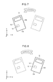
- FIG. 7 is a top view of the electronic device according to the embodiment for illustrating another operation.
- FIG. 8 is a top view of the electronic device according to the embodiment for illustrating still another operation.
- FIG. 9 is a top view of the electronic device according to the embodiment for illustrating a further operation.
- FIG. 10 is a top view of the electronic device according to the embodiment for illustrating a further operation.
- FIG. 11 is a perspective view of the electronic device according to the embodiment for illustrating a further operation.
- FIG. 12 is a perspective view of the electronic device according to the embodiment for illustrating a further operation.
- FIG. 13 is a perspective view of the electronic device according to the embodiment for illustrating a further operation.
- FIG. 14 is a block diagram of another electronic device according to the embodiment.
- FIG. 15 is a top view of a conventional electronic device.
- FIG. 16 is a block diagram of the conventional electronic device.
- FIGS. 1A , 1 B, and 2 are a top view, a perspective view, and a block diagram of electronic device 1001 according to an exemplary embodiment of the present invention, respectively.
- Electronic device 1001 includes case 11 , angular velocity sensor 12 placed in case 11 , processor 13 , data memory 14 , and output unit 17 .
- Processor 13 is connected to angular velocity sensor 12 via terminal 13 A, and receives a signal from sensor 12 .
- Data memory 14 is electrically connected to processor 13 via terminal 13 B.
- Output unit 17 is electrically connected to processor 13 via terminal 13 C.
- Angular velocity sensor 12 is fixed to case 11 . As shown in FIG.
- Angular velocity sensor 12 sends processor 13 signals Sx, Sy, and Sz indicating angular velocities about the X, Y, and Z axes applied on case 11 , respectively.
- Data memory 14 previously stores plural reference profiles.
- Each reference profile is represented by a set of Sx, Sy, and Sz indicating an angular velocity applied on angular velocity sensor 12 (case 11 ).
- FIG. 3 shows plural reference profiles 15 A to 15 F.
- angular velocity sensor 12 detects the angular velocity and sends signals Sx, Sy, and Sz indicating the angular velocity detected to processor 13 .
- Processor 13 selects a set of reference profiles, out of the plural sets of reference profile 15 A to 15 F stored in data memory 14 , closest to signals Sx, Sy, and Sz received from sensor 12 .
- Processor 13 controls output unit 17 according to the selected reference profile.
- FIG. 4 is a block diagram of device 1001 , a portable sound player.
- electronic device 1001 further includes sound memory 18 electrically connected to terminal 13 D of processor 13 .
- Sound memory 18 stores plural sound sources.
- Processor 1 a causes output unit 17 to output the sound sources stored in sound source memory 18 .
- Output unit 17 is implemented by an audio output device, such as a speaker or a headphone.
- a user operates electronic device 1001 , for instance, in the following way.
- the user switches device 1001 from a stop mode in which electronic device 1001 stops to a play mode in which output unit 17 plays a sound source.
- the user switches electronic device 1001 from the play mode to a fast-forward play mode in which output unit 17 fast-forward plays a sound source.
- the user switches electronic device 1001 from the fast-forward play mode to a reverse play mode in which output unit 17 reverse plays a sound source.
- the user switches electronic device 1001 from the reverse play mode to a previous-source play mode in which output unit 17 plays the sound source stored at a position immediately before the sound source currently played selected from the plural sound sources stored in sound source memory 18 .
- the user switches electronic device 1001 to a next sound source play mode in which output unit 17 plays the sound source stored at a position immediately after the sound source currently played selected from the plural sound sources stored in sound source memory 18 .
- the user changes device 1001 from the play mode to a pause mode in which output unit 17 temporarily stops playing a sound source.
- the user changes electronic device 1001 from the pause mode to the play mode, and finally changes electronic device 1001 from the play mode to the stop mode.
- device 1001 operates in the stop mode, in the play mode, in the fast-forward play mode, in the reverse play mode, in the previous sound source play mode, in the next sound source play mode, and in the pause mode.
- FIG. 5 shows signals Sx, Sy, and Sz output from angular velocity sensor 12 when the user operates electronic device 1001 as described above.
- FIGS. 6 to 13 are perspective views of electronic device 1001 being operated.
- the user first moves and rotates case 11 while supporting lower end 11 A of case 11 as a fulcrum from time point t 0 to t 1 shown in FIG. 5 so that the Y-axis forms substantially a conical surface.
- angular velocity sensor 12 is applied angular velocities about the X-axis and the Z-axis to, and is not applied an angular velocity about the Y-axis.
- Angular velocity sensor 12 outputs signals Sx, Sy, and Sz indicating these angular velocities to processor 13 .
- the set of the signals Sx, Sy, and Sz is closest to reference profile 15 A out of plural reference profiles 15 A to 15 F stored in data memory 14 .
- processor 13 selects reference profile 15 A out of reference profiles 15 A to 15 F.
- Reference profile 15 A corresponds to the play mode. Accordingly, processor 13 sends a play signal to output unit 17 to cause electronic device 1001 operate in the play mode, that is, plays one sound source out of the plural sound sources stored in sound source memory 18 from output unit 17 .
- case 11 moves case 11 about the Z-axis reciprocatively once on an XY-plane containing the X-axis and the Y-axis while supporting lower end 11 A of case 11 as a fulcrum from time point t 1 to t 2 shown in FIG. 5 . That is, case 11 moves toward side surface 11 B of case 11 so that the Y-axis and the X-axis form substantially a fan shape, and then case 11 moves towards side surface 11 C opposite to side surface 11 B so that the Y-axis and the X-axis form substantially s fan shape.
- angular velocity sensor 12 is applied an angular velocity about the Z axis to, and is not applied an angular velocity about the X-axis or the Y-axis to.
- Angular velocity sensor 12 sends signals Sx, Sy, and Sz indicating the angular velocity to processor 13 .
- the set of the signals Sx, Sy, and Sz is closest to reference profile 15 C out of plural reference profiles 15 A to 15 F stored in data memory 14 .
- processor 13 selects reference profile 15 C out of reference profiles 15 A to 15 F.
- Reference profile 15 C corresponds to the fast-forward play mode.
- Processor 13 sends a fast-forward play signal to output unit 17 to cause electronic device 1001 to operate in the fast-forward play mode, that is, fast-forward plays a sound source from output unit 17 .
- the user may move case 11 about the Z-axis while holding case 11 slightly inclining about the Y-axis or the X-axis by, e.g. 15 degrees.
- angular velocity sensor 12 is applied not only the angular velocity about the Z-axis, but also angular velocities about the Y-axis and the X-axis.
- the angular velocities about the Y-axis and the X-axis are extremely smaller than the angular velocity about the Z-axis, thus causing the amplitude of signal Sz to be extremely larger than the amplitudes of signals Sx and Sy.
- Processor 13 neglects signals Sx and Sy with ratios of the amplitudes of signals Sx and Sy to the maximum amplitude out of the amplitudes of signals Sx to Sz being smaller than a predetermined ratio value to qualify the amplitudes of signals Sx and Sy as zero, thus selecting reference profile 15 C out of plural reference profiles 15 A to 15 F.
- processor 13 can neglect signal Sy with an amplitude smaller than a predetermined value out of the amplitudes of signals Sx to Sz to qualify the amplitude of signal Sy as zero.
- case 11 moves case 11 once reciprocatively about the Z-axis on the XY plane containing the X-axis and the Y-axis while supporting lower end 11 A of case 11 as a fulcrum in a direction opposite to the direction shown in FIG. 7 from time point t 2 to t 3 shown in FIG. 5 . That is, case 11 moves towards side surface 11 C of case 11 so that the Y-axis and the X-axis form substantially s fan shape, and then, case 11 moves towards side surface 11 B so that the Y-axis and the X-axis form substantially s fan shape.
- angular velocity sensor 12 is applied angular velocity about the Z-axis to, and is not applied an angular velocity about the X-axis or the Y-axis to.
- Angular velocity sensor 12 sends signals Sx, Sy, and Sz indicating the angular velocity to processor 13 .
- the set of the signals Sx, Sy, and Sz is closest to reference profile 15 E out of plural reference profiles 15 A to 15 F stored in data memory 14 .
- Processor 13 selects reference profile 15 E out of reference profiles 15 A to 15 F.
- Reference profile 15 E corresponds to the reverse play mode.
- Processor 13 sends a reverse play signal to output unit 17 to cause electronic device 1001 to operate in the reverse play mode, that is, reverse plays a sound source from output unit 17
- case 11 thrice reciprocatively about the Z-axis on the XY plane containing the X-axis and the Y-axis while supporting lower end 11 A of case 11 as a fulcrum from time point t 3 to t 4 shown in FIG. 5 . That is, case 11 moves towards side surface 11 B of case 11 so that the Y-axis and the X-axes form substantially s fan shape, and then, case 11 moves towards side surface 11 C opposite to side surface 11 B so that the Y-axis and the X-axis form substantially s fan shape. After that, the above movement is repeated twice.
- angular velocity sensor 12 is applied an angular velocity about the Z-axis to, and is not applied an angular velocity about the X-axis or the Y-axis.
- Angular velocity sensor 12 sends signals Sx, Sy, and Sz indicating the angular velocity to processor 13 .
- the set of the signals Sx, Sy, and Sz is closest to reference profiles 15 F out of plural reference profiles 15 A to 15 F stored in data memory 14 .
- Processor 13 selects reference profile 15 F out of reference profiles 15 A to 15 F.
- Reference profile 15 F corresponds to the previous sound source play mode.
- Processor 13 sends a previous sound source play signal to output unit 17 to cause electronic device 1001 to operate in the previous sound source play mode, that is, to play, output unit 17 , a sound source positioned immediately before the sound source currently played out of the plural sound sources stored in sound source memory 18 .
- case 11 thrice reciprocatively in the direction opposite to the direction shown in FIG. 9 about the Z-axis on the XY plane containing the X-axis and the Y-axes while supporting lower end 11 A of case 11 as a fulcrum from time point t 4 to t 5 shown in FIG. 5 . That is, case 11 moves towards side surface 11 C of case 11 so that the Y-axis and the X-axis form substantially s fan shape, an then, case 11 moves towards side surface 11 B so that the Y-axis and the X-axis form substantially fan shape. After that, the movement is repeated twice.
- angular velocity sensor 12 is applied angular velocity about the Z-axis, an dis not applied an angular velocity about the X-axis or the Y-axis.
- Angular velocity sensor 12 sends signals Sx, Sy, and Sz indicating the angular velocity to processor 13 .
- the set of the signals Sx, Sy, and Sz is closest to reference profile 15 D out of plural reference profiles 15 A to 15 F stored in data memory 14 .
- Processor 13 selects reference profile 15 D out of reference profiles 15 A to 15 F.
- Reference profile 15 D corresponds to the next sound source play mode.
- Processor 13 sends a next sound source play signal to output unit 17 to cause electronic device 1001 to operate in the next sound source play mode, that is, to play, from output unit 17 , a sound source positioned immediately after the currently played sound source out of the plural sound sources stored in sound source memory 18 .
- case 11 moves once case 11 about the X-axis on the YZ plane containing the Y-axis and the Z-axis while supporting lower end 11 A of case 11 as a fulcrum from time point t 5 to t 6 shown in FIG. 5 . That is, case 11 moves in a direction from front surface 11 D to back surface 11 E of case 11 so that the Y-axis and the Z-axis form substantially s fan shape.
- angular velocity sensor 12 is applied an angular velocity about the X-axis, and is not applied an angular velocity about the Y-axis or the Z-axis.
- Angular velocity sensor 12 sends signals Sx, Sy, and Sz indicating the angular velocity to processor 13 .
- the set of the signals Sx, Sy, and Sz is closest to reference profile 15 B out of plural reference profiles 15 A to 15 F stored in data memory 14 .
- Processor 13 selects reference profile 15 B out of reference profiles 15 A to 15 F.
- Reference profile 15 B corresponds to the pause mode.
- Processor 13 sends a pause signal to output unit 17 to cause electronic device 1001 to operate in the pause mode, that is, to temporarily stop the sound source currently played from output unit 17 .
- case 11 moves in a direction from front surface 11 D to back surface 11 E of case 11 so that the Y-axis and the Z-axis form substantially a fan shape.
- angular velocity sensor 12 is applied an angular velocity centering about the X-axis, and is not applied an angular velocity about the Y-axis or the Z-axis.
- Angular velocity sensor 12 sends signals Sx, Sy, and Sz indicating the angular velocity to processor 13 .
- the set of the signals Sx, Sy, and Sz is closest to reference profile 15 B out of plural reference profiles 15 A to 15 F stored in data memory 14 .
- Processor 13 selects reference profile 15 B out of reference profiles 15 A to 15 F.
- Reference profile 15 B corresponds to the pause mode.
- processor 13 sends a play signal to output unit 17 to change the operation mode of electronic device 1001 from the pause mode to the play mode to cause electronic device 1001 to play, from output unit 17 , the sound source temporarily stopped.
- angular velocity sensor 12 is applied angular velocities about the X-axis and the Z-axis to, and is not applied an angular velocity about the Y-axis.
- Angular velocity sensor 12 sends signals Sx, Sy, and Sz indicating the angular velocities to processor 13 .
- the set of the signals Sx, Sy, and Sz is closest to reference profile 15 A out of plural reference profiles 15 A to 15 F stored in data memory 14 shown in FIG. 3 .
- Processor 13 selects reference profile 15 A out of reference profiles 15 A to 15 F.
- Reference profile 15 A corresponds to the play mode as shown in FIG. 3 .
- processor 13 selects reference profile 15 A corresponding to the play mode while electronic device 1001 operates in the play mode, processor 13 sends a stop signal to output unit 17 to change the operation mode of electronic device 1001 from the play mode to the stop mode, that is, causes electronic device 1001 to stop currently playing the sound source from output unit 17 .
- output unit 17 operates in plural operation modes, such as the play mode, the fast-forward play mode, the reverse play mode, the previous sound source play mode, and the next sound source play mode, corresponding to reference profiles 15 A to 15 F, respectively.
- Processor 13 receives signals Sx, Sy, and Sz sent from angular velocity sensor 12 and selects a reference profile out of reference profiles 15 A to 15 F based on the signals Sx, Sy, and Sz. Then, processor 13 causes output unit 17 to operate in an operation mode corresponding to the selected reference profile.
- Sound source memory 18 stores plural sound sources. Processor 13 operates to cause output unit 17 to output the stored sound source in an operation mode corresponding to the selected reference profile. Sound source memory 18 stores plural sound sources. Processor 13 selects a sound source out of the plural sound sources corresponding to eth elected reference profile to cause output unit 17 to output the selected sound source.
- FIG. 3 shows sets of signals Sx, Sy, and Sz sent from angular velocity sensor 12 .
- Processor 13 compares reference profiles 15 A to 15 F with the sets of signals Sx, Sy, and Sz to select a reference profile out of the reference profiles 15 A to 15 F closest to the set of signals Sx, Sy, and Sz.
- Processor 13 can compare a set of signals obtained by differentiating or integrating the signals sent from angular velocity sensor 12 with plural reference profiles corresponding to the set of signals.
- Electronic device 1001 shown in FIG. 4 includes sound source memory 18 storing plural sound sources, but does not necessarily store any sound source.
- the electronic device according to the embodiment can include a receiver for receiving plural broadcasts instead of sound source memory 18 .
- This electronic device can select a broadcast out of the plural broadcasts by the user applying an angular acceleration to case 11 as shown in FIGS. 6 to 13 .
- FIG. 14 is a block diagram of another electronic device 1002 according to the embodiment. Components identical to those of electronic device 1001 shown in FIGS. 1 and 4 are denoted by the same reference numerals, and their description will be omitted.
- Electronic device 1002 shown in FIG. 14 further includes A/D converter 19 provided between angular velocity sensor 12 and processor 13 of electronic device 1001 shown in FIGS. 1 and 4 . Signals Sx, Sy, and Sz sent from angular velocity sensor 12 are analog signals.
- A/D converter 19 converts signals Sx, Sy, and Sz to digital signals and sends the digital signals to processor 13 .
- the reference profiles stored in data memory 14 of electronic device 1002 are digital data, hence allowing processor 13 to control output unit 17 at a high speed.
- Electronic device 1002 further includes display 20 electrically connected to processor 13 via terminal 13 E.
- Processor 13 changes an indication on display 20 in response to the operation mode to play a sound source, thereby allowing the user to realize the operation mode to play a sound source.
- display 20 produces an indication changing according to an operation mode corresponding to the selected reference profile.
- reference profiles 15 A to 15 F indicate an angular velocity about the Y-axis.
- processor 13 compares signals Sx and Sz with reference profiles 15 A to 15 F. This operation allows processor 13 selects a reference profile closest to signals Sx and Sz out of reference profiles 15 A to 15 F and controls output unit 17 based on the elected reference profile.
- the processor can judges that the angular velocity is applied not in order to operate electronic device 1001 , but due to otherwise (e.g. conveying electronic device 1001 ). In this case, even if signals Sx and Sz with a predetermined amplitude are sent from angular velocity sensor 12 , processor 13 does not change the operation mode of output unit 17 . An angular velocity occurs artificially rather than an acceleration does. Hence, electronic device 1001 operating with angular velocity is prevented more from erroneously operating due to conveying or a shock than a device detecting an acceleration.
- An electronic device can be operated by a user with a quick response, hence being useful for an electronic device, such as a portable sound source player.
Landscapes
- Engineering & Computer Science (AREA)
- Theoretical Computer Science (AREA)
- Computer Hardware Design (AREA)
- Physics & Mathematics (AREA)
- General Engineering & Computer Science (AREA)
- General Physics & Mathematics (AREA)
- Human Computer Interaction (AREA)
- Radar, Positioning & Navigation (AREA)
- Remote Sensing (AREA)
- Gyroscopes (AREA)
- Position Input By Displaying (AREA)
- Navigation (AREA)
Abstract
Description
- 11 Case
- 12 Angular Velocity Sensor
- 13 Processor
- 14 Data Memory
- 17 Output Unit
- 18 Sound Memory
- 19 A/D Converter
- 20 Display
- 1001 Electronic Device
- 1002 Electronic Device
Claims (12)
Applications Claiming Priority (3)
| Application Number | Priority Date | Filing Date | Title |
|---|---|---|---|
| JP2007-316908 | 2007-12-07 | ||
| JP2007316908 | 2007-12-07 | ||
| PCT/JP2008/003356 WO2009072240A1 (en) | 2007-12-07 | 2008-11-18 | Electronic device |
Publications (2)
| Publication Number | Publication Date |
|---|---|
| US20100265082A1 US20100265082A1 (en) | 2010-10-21 |
| US8830077B2 true US8830077B2 (en) | 2014-09-09 |
Family
ID=40717424
Family Applications (1)
| Application Number | Title | Priority Date | Filing Date |
|---|---|---|---|
| US12/741,467 Active 2030-09-29 US8830077B2 (en) | 2007-12-07 | 2008-11-18 | Electronic device |
Country Status (4)
| Country | Link |
|---|---|
| US (1) | US8830077B2 (en) |
| JP (1) | JP5493864B2 (en) |
| CN (1) | CN101868771B (en) |
| WO (1) | WO2009072240A1 (en) |
Cited By (3)
| Publication number | Priority date | Publication date | Assignee | Title |
|---|---|---|---|---|
| USD805053S1 (en) * | 2016-09-23 | 2017-12-12 | Hon Hai Precision Industry Co., Ltd. | Portable player |
| USD805497S1 (en) * | 2016-10-28 | 2017-12-19 | Hon Hai Precision Industry Co., Ltd. | Portable player |
| USD806050S1 (en) * | 2016-09-23 | 2017-12-26 | Hon Hai Precision Industry Co., Ltd. | Portable player |
Families Citing this family (4)
| Publication number | Priority date | Publication date | Assignee | Title |
|---|---|---|---|---|
| JP2011205173A (en) * | 2010-03-24 | 2011-10-13 | Panasonic Corp | Playback device, playback control method, and program |
| JP6442769B2 (en) * | 2015-06-03 | 2018-12-26 | 富士通コネクテッドテクノロジーズ株式会社 | Information processing apparatus, gesture detection method, and program |
| JP6670163B2 (en) * | 2016-04-28 | 2020-03-18 | シャープ株式会社 | Information processing device, mobile terminal, function execution method, program |
| JP6789668B2 (en) * | 2016-05-18 | 2020-11-25 | ソニーモバイルコミュニケーションズ株式会社 | Information processing equipment, information processing system, information processing method |
Citations (18)
| Publication number | Priority date | Publication date | Assignee | Title |
|---|---|---|---|---|
| JPH07160411A (en) | 1993-12-06 | 1995-06-23 | Sony Corp | Input device |
| JPH1199284A (en) | 1997-09-30 | 1999-04-13 | Sony Corp | controller |
| US6271831B1 (en) * | 1997-04-03 | 2001-08-07 | Universal Electronics Inc. | Wireless control and pointer system |
| US20020084912A1 (en) * | 2000-12-29 | 2002-07-04 | Stefanik John R. | Remote control device with feedback apparatus |
| US6433690B2 (en) * | 1998-10-27 | 2002-08-13 | Sarcos, L.C. | Elderly fall monitoring method and device |
| WO2005019987A2 (en) | 2003-08-18 | 2005-03-03 | Apple Comuter, Inc. | Movable touch pad with added functionality |
| CN1601447A (en) | 2004-09-30 | 2005-03-30 | 清华大学 | Interdynamic information perception method of cell phone games and external smart game platform of cell phone |
| US20060236761A1 (en) * | 2005-04-22 | 2006-10-26 | Hitachi Metals, Ltd. | Free fall detection device |
| US20060281453A1 (en) * | 2005-05-17 | 2006-12-14 | Gesturetek, Inc. | Orientation-sensitive signal output |
| US20070013539A1 (en) * | 2005-07-15 | 2007-01-18 | Samsung Electronics Co., Ltd. | Method, apparatus, and medium controlling and playing sound effect by motion detection |
| JP2007286812A (en) | 2006-04-14 | 2007-11-01 | Sony Corp | Portable electronic device, user interface control method, program |
| US20070265088A1 (en) * | 2006-05-09 | 2007-11-15 | Nintendo Co., Ltd. | Storage medium storing game program, game apparatus, and game system |
| US7301528B2 (en) * | 2004-03-23 | 2007-11-27 | Fujitsu Limited | Distinguishing tilt and translation motion components in handheld devices |
| US20080055243A1 (en) * | 1995-10-06 | 2008-03-06 | Gordon Gary B | Method of operating an optical mouse |
| US20080300055A1 (en) * | 2007-05-29 | 2008-12-04 | Lutnick Howard W | Game with hand motion control |
| US20090009478A1 (en) * | 2007-07-02 | 2009-01-08 | Anthony Badali | Controlling user input devices based upon detected attitude of a handheld electronic device |
| US20090066506A1 (en) * | 2007-09-07 | 2009-03-12 | Niizawa Derek T | Electronic device with circuitry operative to change an orientation of an indicator and method for use therewith |
| US8242894B2 (en) * | 2006-05-08 | 2012-08-14 | Sony Computer Entertainment Inc. | Remote control system and remote control method |
Family Cites Families (6)
| Publication number | Priority date | Publication date | Assignee | Title |
|---|---|---|---|---|
| US5867573A (en) * | 1996-02-06 | 1999-02-02 | Lucent Technologies Inc. | Telephone handset interface with feedback control |
| JP2002374572A (en) * | 2001-06-15 | 2002-12-26 | Yamaha Corp | Mobile phone |
| JP2003271302A (en) * | 2002-03-19 | 2003-09-26 | Sony Corp | Motion information detection device, operation information transmission system, operation information transmission method, and computer program |
| JP2004023475A (en) * | 2002-06-17 | 2004-01-22 | Nippon Telegr & Teleph Corp <Ntt> | Portable notification device and notification management system |
| JP4117352B2 (en) * | 2002-11-12 | 2008-07-16 | 株式会社ソニー・コンピュータエンタテインメント | File processing method and apparatus capable of using this method |
| JP4204542B2 (en) * | 2004-12-28 | 2009-01-07 | シャープ株式会社 | Portable terminal device, program, and recording medium |
-
2008
- 2008-11-18 US US12/741,467 patent/US8830077B2/en active Active
- 2008-11-18 JP JP2009544555A patent/JP5493864B2/en active Active
- 2008-11-18 CN CN200880116968.3A patent/CN101868771B/en active Active
- 2008-11-18 WO PCT/JP2008/003356 patent/WO2009072240A1/en not_active Ceased
Patent Citations (20)
| Publication number | Priority date | Publication date | Assignee | Title |
|---|---|---|---|---|
| JPH07160411A (en) | 1993-12-06 | 1995-06-23 | Sony Corp | Input device |
| US20080055243A1 (en) * | 1995-10-06 | 2008-03-06 | Gordon Gary B | Method of operating an optical mouse |
| US6271831B1 (en) * | 1997-04-03 | 2001-08-07 | Universal Electronics Inc. | Wireless control and pointer system |
| JPH1199284A (en) | 1997-09-30 | 1999-04-13 | Sony Corp | controller |
| US6433690B2 (en) * | 1998-10-27 | 2002-08-13 | Sarcos, L.C. | Elderly fall monitoring method and device |
| US20020084912A1 (en) * | 2000-12-29 | 2002-07-04 | Stefanik John R. | Remote control device with feedback apparatus |
| WO2005019987A2 (en) | 2003-08-18 | 2005-03-03 | Apple Comuter, Inc. | Movable touch pad with added functionality |
| US7499040B2 (en) | 2003-08-18 | 2009-03-03 | Apple Inc. | Movable touch pad with added functionality |
| US7301528B2 (en) * | 2004-03-23 | 2007-11-27 | Fujitsu Limited | Distinguishing tilt and translation motion components in handheld devices |
| CN1601447A (en) | 2004-09-30 | 2005-03-30 | 清华大学 | Interdynamic information perception method of cell phone games and external smart game platform of cell phone |
| US20060236761A1 (en) * | 2005-04-22 | 2006-10-26 | Hitachi Metals, Ltd. | Free fall detection device |
| US20060281453A1 (en) * | 2005-05-17 | 2006-12-14 | Gesturetek, Inc. | Orientation-sensitive signal output |
| US20070013539A1 (en) * | 2005-07-15 | 2007-01-18 | Samsung Electronics Co., Ltd. | Method, apparatus, and medium controlling and playing sound effect by motion detection |
| JP2007286812A (en) | 2006-04-14 | 2007-11-01 | Sony Corp | Portable electronic device, user interface control method, program |
| US20080001770A1 (en) | 2006-04-14 | 2008-01-03 | Sony Corporation | Portable electronic apparatus, user interface controlling method, and program |
| US8242894B2 (en) * | 2006-05-08 | 2012-08-14 | Sony Computer Entertainment Inc. | Remote control system and remote control method |
| US20070265088A1 (en) * | 2006-05-09 | 2007-11-15 | Nintendo Co., Ltd. | Storage medium storing game program, game apparatus, and game system |
| US20080300055A1 (en) * | 2007-05-29 | 2008-12-04 | Lutnick Howard W | Game with hand motion control |
| US20090009478A1 (en) * | 2007-07-02 | 2009-01-08 | Anthony Badali | Controlling user input devices based upon detected attitude of a handheld electronic device |
| US20090066506A1 (en) * | 2007-09-07 | 2009-03-12 | Niizawa Derek T | Electronic device with circuitry operative to change an orientation of an indicator and method for use therewith |
Non-Patent Citations (2)
| Title |
|---|
| Chinese Office Action dated Jun. 24, 2011. |
| International Search Report for PCT/JP2008/003356. |
Cited By (3)
| Publication number | Priority date | Publication date | Assignee | Title |
|---|---|---|---|---|
| USD805053S1 (en) * | 2016-09-23 | 2017-12-12 | Hon Hai Precision Industry Co., Ltd. | Portable player |
| USD806050S1 (en) * | 2016-09-23 | 2017-12-26 | Hon Hai Precision Industry Co., Ltd. | Portable player |
| USD805497S1 (en) * | 2016-10-28 | 2017-12-19 | Hon Hai Precision Industry Co., Ltd. | Portable player |
Also Published As
| Publication number | Publication date |
|---|---|
| CN101868771B (en) | 2013-07-31 |
| WO2009072240A1 (en) | 2009-06-11 |
| CN101868771A (en) | 2010-10-20 |
| US20100265082A1 (en) | 2010-10-21 |
| JP5493864B2 (en) | 2014-05-14 |
| JPWO2009072240A1 (en) | 2011-04-21 |
Similar Documents
| Publication | Publication Date | Title |
|---|---|---|
| US8830077B2 (en) | Electronic device | |
| EP1744301A1 (en) | Method, apparatus, and medium for controlling and playing sound effect by motion detection | |
| US8089352B2 (en) | Control apparatus and method | |
| US6998966B2 (en) | Mobile communication device having a functional cover for controlling sound applications by motion | |
| US20110311083A1 (en) | Portable audio device with microphone and controller | |
| US20090034209A1 (en) | Multi-module combination type portable electronic device | |
| EP2485120B1 (en) | Control device, control method, and program | |
| US20070291112A1 (en) | Remote control having magnetic sensors for determining motions of the remote control in three dimensions that correspond to associated signals that can be transmitted from the remote control | |
| JP2014508444A (en) | Audio processing device | |
| WO2013175631A1 (en) | Operation device, information processing system, and information processing method | |
| JP2009100366A (en) | Remote control device, remote control system and electrical equipment | |
| KR20190095789A (en) | Method for playing audio data using dual speaker and electronic device thereof | |
| US20090309825A1 (en) | User interface, method, and computer program for controlling apparatus, and apparatus | |
| JPWO2013175630A1 (en) | Operating device, information processing system, and communication method | |
| US20080074281A1 (en) | Remote control transmitter which is capable of controlling a plurality of light fittings without the need for a slidable switch | |
| CN106998521A (en) | Loudspeaker control method, device and terminal equipment | |
| US11974101B2 (en) | Reproduction device, reproduction system, and reproduction method | |
| JP5644748B2 (en) | Audio equipment | |
| KR100664961B1 (en) | Mobile devices that support multiple sound outputs | |
| KR101021009B1 (en) | Volume control | |
| KR102491646B1 (en) | Method for processing a audio signal based on a resolution set up according to a volume of the audio signal and electronic device thereof | |
| KR20110065052A (en) | Mobile communication terminal | |
| KR101014961B1 (en) | Wireless communication terminal having music playing function by acceleration detection and its method | |
| TW201237761A (en) | Communication device and a switch method | |
| US20070257808A1 (en) | Remote control for a multimedia player |
Legal Events
| Date | Code | Title | Description |
|---|---|---|---|
| AS | Assignment |
Owner name: PANASONIC CORPORATION, JAPAN Free format text: ASSIGNMENT OF ASSIGNORS INTEREST;ASSIGNORS:UEMURA, TAKESHI;NOZOE, TOSHIYUKI;REEL/FRAME:024574/0855 Effective date: 20100330 |
|
| STCF | Information on status: patent grant |
Free format text: PATENTED CASE |
|
| MAFP | Maintenance fee payment |
Free format text: PAYMENT OF MAINTENANCE FEE, 4TH YEAR, LARGE ENTITY (ORIGINAL EVENT CODE: M1551) Year of fee payment: 4 |
|
| AS | Assignment |
Owner name: CONVERSANT INTELLECTUAL PROPERTY MANAGEMENT INC., Free format text: ASSIGNMENT OF ASSIGNORS INTEREST;ASSIGNOR:PANASONIC CORPORATION;REEL/FRAME:045773/0387 Effective date: 20180423 |
|
| AS | Assignment |
Owner name: CPPIB CREDIT INVESTMENTS, INC., CANADA Free format text: AMENDED AND RESTATED U.S. PATENT SECURITY AGREEMENT (FOR NON-U.S. GRANTORS);ASSIGNOR:CONVERSANT INTELLECTUAL PROPERTY MANAGEMENT INC.;REEL/FRAME:046900/0136 Effective date: 20180731 |
|
| AS | Assignment |
Owner name: CONVERSANT INTELLECTUAL PROPERTY MANAGEMENT INC., CANADA Free format text: RELEASE BY SECURED PARTY;ASSIGNOR:CPPIB CREDIT INVESTMENTS INC.;REEL/FRAME:054344/0143 Effective date: 20201028 |
|
| AS | Assignment |
Owner name: MOSAID TECHNOLOGIES INCORPORATED, CANADA Free format text: CHANGE OF NAME;ASSIGNOR:CONVERSANT INTELLECTUAL PROPERTY INC.;REEL/FRAME:058794/0701 Effective date: 20210401 |
|
| MAFP | Maintenance fee payment |
Free format text: PAYMENT OF MAINTENANCE FEE, 8TH YEAR, LARGE ENTITY (ORIGINAL EVENT CODE: M1552); ENTITY STATUS OF PATENT OWNER: LARGE ENTITY Year of fee payment: 8 |
|
| AS | Assignment |
Owner name: MOSAID TECHNOLOGIES INCORPORATED, CANADA Free format text: CORRECTIVE ASSIGNMENT TO CORRECT THE CONVEYING PARTY'S NAME FROM CONVERSANT INTELLECTUAL PROPERTY INC. TO CONVERSANT INTELLECTUAL PROPERT MANAGEMENT INC. PREVIOUSLY RECORDED AT REEL: FRAME: . ASSIGNOR(S) HEREBY CONFIRMS THE CHANGE OF NAME;ASSIGNOR:CONVERSANT INTELLECTUAL PROPERTY MANAGEMENT INC.;REEL/FRAME:064689/0057 Effective date: 20210401 |
|
| AS | Assignment |
Owner name: MOSAID TECHNOLOGIES INCORPORATED, CANADA Free format text: CORRECTIVE ASSIGNMENT TO CORRECT THE CONVEYING PARTY'S NAME PREVIOUSLY RECORDED ON REEL 058794 FRAME 0701. ASSIGNOR(S) HEREBY CONFIRMS THE CHANGE OF NAME;ASSIGNOR:CONVERSANT INTELLECTUAL PROPERTY MANAGEMENT INC.;REEL/FRAME:064584/0672 Effective date: 20210401 |