US8827863B2 - Planet carrier arrangements - Google Patents
Planet carrier arrangements Download PDFInfo
- Publication number
- US8827863B2 US8827863B2 US13/669,836 US201213669836A US8827863B2 US 8827863 B2 US8827863 B2 US 8827863B2 US 201213669836 A US201213669836 A US 201213669836A US 8827863 B2 US8827863 B2 US 8827863B2
- Authority
- US
- United States
- Prior art keywords
- carrier
- planet
- legs
- planet carrier
- pins
- Prior art date
- Legal status (The legal status is an assumption and is not a legal conclusion. Google has not performed a legal analysis and makes no representation as to the accuracy of the status listed.)
- Expired - Fee Related
Links
Images


Classifications
-
- F—MECHANICAL ENGINEERING; LIGHTING; HEATING; WEAPONS; BLASTING
- F16—ENGINEERING ELEMENTS AND UNITS; GENERAL MEASURES FOR PRODUCING AND MAINTAINING EFFECTIVE FUNCTIONING OF MACHINES OR INSTALLATIONS; THERMAL INSULATION IN GENERAL
- F16H—GEARING
- F16H1/00—Toothed gearings for conveying rotary motion
- F16H1/28—Toothed gearings for conveying rotary motion with gears having orbital motion
-
- F—MECHANICAL ENGINEERING; LIGHTING; HEATING; WEAPONS; BLASTING
- F16—ENGINEERING ELEMENTS AND UNITS; GENERAL MEASURES FOR PRODUCING AND MAINTAINING EFFECTIVE FUNCTIONING OF MACHINES OR INSTALLATIONS; THERMAL INSULATION IN GENERAL
- F16H—GEARING
- F16H57/00—General details of gearing
- F16H57/08—General details of gearing of gearings with members having orbital motion
- F16H57/082—Planet carriers
-
- F—MECHANICAL ENGINEERING; LIGHTING; HEATING; WEAPONS; BLASTING
- F05—INDEXING SCHEMES RELATING TO ENGINES OR PUMPS IN VARIOUS SUBCLASSES OF CLASSES F01-F04
- F05B—INDEXING SCHEME RELATING TO WIND, SPRING, WEIGHT, INERTIA OR LIKE MOTORS, TO MACHINES OR ENGINES FOR LIQUIDS COVERED BY SUBCLASSES F03B, F03D AND F03G
- F05B2260/00—Function
- F05B2260/40—Transmission of power
- F05B2260/403—Transmission of power through the shape of the drive components
- F05B2260/4031—Transmission of power through the shape of the drive components as in toothed gearing
- F05B2260/40311—Transmission of power through the shape of the drive components as in toothed gearing of the epicyclic, planetary or differential type
Definitions
- the present invention is related to planet carriers used in planetary gear systems, and in particular to planet carriers used in wind turbine gearboxes.
- a carrier In a planetary gear system, the function of a carrier is to transmit torque or torsion load from the input shaft into the planet pins, as evenly as possible. Particularly in wind turbine applications, the carrier is also transmitting the weight of the gearbox back to the wind turbine rotor shaft. The most efficient way of doing this is a cylinder, but a planet carrier must have gaps for the planet gears. The gaps cause the shear to be concentrated in the legs. Flexibility of the planet carrier is critical to the alignment of the planet gear meshes.
- Ribs can cause local stress raisers, which can cause fatigue failures. This is more of a problem in brittle materials, such as castings. Ribs also make for a more complex casting.
- Excessive wind-up causes the planet pins to tilt, which in turn causes misalignment in the planet gear mesh.
- Carrier wind-up can also cause an imbalance of loading between the upwind and downwind planet bearings. Twisting of the pins in the bores in the carrier can cause excessive stress in the carrier (or pin), resulting in local yielding or fatigue failure.
- Increased interference fit causes greater stress in the region, increasing risk of yield or fatigue problems. Tighter fits also make assembling and disassembling more costly and risks of damage during assembly increase.
- Shorter legs mean a thinner gear, which reduces the load carrying capacity or life of the gear.
- legs of carrier may only be possible if there is space between the planet gears to do so. Reducing the planet gear size reduces the ratio change of the planet stage. Thicker legs increase the weight of the carrier.
- a change to a stiffer material would add cost in raw material, and may require more complex casting procedures (e.g. change from SG iron to cast steel)
- the role or function of the planet carrier is to transmit torque loads and, particularly for wind turbine application, transmit the weight of the gear box.
- FIGS. 7 and 8 show planet carrier 700 having a shaft 702 , and which is supported by bearing 704 on the downwind side of the gearbox and by a very large bearing 706 on the upwind side.
- Large bearing 706 is able to pass over the input flange.
- large bearings are expensive, and as the carrier bearings are usually lightly loaded, a larger bearing further reduces the loading, with a concomitant increase in the risk of skidding failure in the bearing.
- FIG. 8 which shows planet carrier 700 having a shaft 702 supported by bearing 704 on the downwind side of the gearbox, smaller diameter support 706 can be used by splitting the carrier or the upwind bearing.
- Split bearings are unlikely to be reliable, and the use of a split carrier requires an additional joint, at a smaller size than that with the rotor shaft, which would be very highly loaded, difficult to manufacture and add cost.
- planet carrier 700 , 800 is supported on the non-rotor side of the carrier by bearing 704 , 804 to provide the necessary radial support.
- the present invention has features designed to increase the stiffness of the carrier structure.
- the invention uses a structurally significant extension to the leg in the axial direction, and strongly connects the legs on each side together. This reduces twisting of the legs on each side relative to the carrier plate.
- the invention places material at the outermost edge of the available space.
- a planet carrier which is adapted to transmit a torsion load from an input member into a plurality of planet pins.
- the planet carrier has a first and second carrier plate, carrier legs disposed between the first and second carrier plates, and a member connected to the carrier legs and one of the carrier plates.
- the member is resistant to buckling caused by torsional stress and increases a torsional stiffness of the planet carrier, so that a torsion load is transmitted evenly from the input member into the planet pins without twisting the planet carrier.
- the member is a flange, rib or rim.
- the member is cylindrical or frustoconical. The depth of material in the plane of the loading determines the operational stiffness in this design.
- the member extends from the carrier legs to form a single kinematic structure comprising the legs and the member.
- the carrier plates are connected to the assembly comprising the member and the legs.
- the planet carrier additionally comprises planet pins, which are connected to the assembly comprising the member and the legs via the carrier plates. This means that torsion load is transmitted to the planet pins without twisting the carrier plate.
- the member extends from the carrier plate to form a single kinematic structure comprising the member and the carrier plate.
- carrier plates can be thin, as they are not required to resist the bending generated in a prior art planet carrier.
- the assembly comprising the member and the carrier plate is connected to the carrier legs and twisting of the legs relative to the carrier plate is resisted.
- the carrier legs comprise steel columns located between two carrier plates.
- the member is located around a periphery of the planet carrier.
- the member is located radially inwardly of a periphery of the planet carrier, and places material at the edge of the available space.
- the member is connected to the input member.
- the planet carrier additionally comprises a further member connected to the carrier legs and one of the carrier plates so that one member is located at one end of the planet carrier and the further member is located at the other end of the planet carrier.
- a further member connected to the carrier legs and one of the carrier plates so that one member is located at one end of the planet carrier and the further member is located at the other end of the planet carrier.
- a gearbox comprising the planet carrier described above.
- a bearing arrangement for a planet carrier located on a shaft on one side of the carrier and adapted to react to tilting moments applied to the carrier.
- the arrangement also supports radial loads, such as gearbox mass and unbalanced loads from the gears.
- bearings located on the other side of the carrier.
- the bearing arrangement comprises a pair of bearing means located adjacently on the shaft.
- the pair of bearing means may comprise a DTRB.
- the pair of bearing means may comprise a first bearing and a second bearing.
- the first bearing may be separated from the second bearing.
- the first bearing may be separated from the second bearing by a spacer.
- a wind turbine comprising the gearbox described above.
- a member for a planet carrier comprising a first and second carrier plate and a plurality of carrier legs disposed between the first and second carrier plates.
- the member is adapted to connect to the carrier legs and one of the carrier plates, and is resistant to buckling caused by torsional stress. This means that, in use, the member increases a torsional stiffness of the planet carrier so that a torsion load is transmitted evenly from an input member into the planet pins without twisting the planet carrier.
- the member is a flange, rib or rim.
- the member is cylindrical or frustoconical. The depth of material in the plane of the loading determines the operational stiffness in this design.
- the member is additionally adapted to connect to either end of the planet carrier.
- the present invention also provides a bearing arrangement which can be advantageously utilised with the planet carriers disclosed above.
- FIGS. 1 and 2 show sectional views of an embodiment of the planet carrier of the present invention, the former showing the location of planet pins and a planet gear, in which the member is frustoconical;
- FIGS. 3 and 4 show sectional views of an embodiment of the planet carrier of the present invention, the former showing the location of planet pins and a planet gear, in which the member is a flange;
- FIG. 5A shows a diagrammatic view of an embodiment of the planet carrier of the present invention, in which the member extending from the planet carrier legs towards the input shaft is cylindrical;
- FIG. 5B shows a diagrammatic view of an embodiment of the planet carrier of the present invention, in which the member extending from the planet carrier legs towards the input shaft is conical;
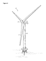
- FIG. 6 is a perspective view of one example of a wind turbine
- FIG. 7 shows a large bearing used to support a planet carrier
- FIG. 8 shows a split bearing/split carrier arrangement to support a planet carrier
- FIG. 9 shows a diagrammatic view of an embodiment of the planet carrier bearing arrangement of the present invention.
- carrier plates 102 In known designs, the function of carrier plates 102 is to hold planet pins 104 and transfer load from the planet carrier bearing to legs 108 .
- the function of legs 108 is to join carrier plates 102 together
- Planet pins 104 are connected to the member/leg structure 108 / 110 via carrier plates 102 .
- carrier plate 102 holding planet pins 104 is effectively immobilised between the very stiff leg 108 and rib/flange 110 structure.
- the function of flange 110 is to stiffen carrier plate 102 and connect legs 108 together, so it is most effective when it is connected directly to legs 108 .
- Member 110 anchors leg 108 to carrier plate 102 , and legs 108 to each other. Member 110 is part of the structure that makes up the legs 108 which means that functionally legs 108 are not discrete components as they are now strongly interconnected.
- the present invention also includes a member for a planet carrier which is adapted to connect to the carrier legs and one of the carrier plates, and is resistant to buckling caused by torsional stress. This means that, in use, the member increases a torsional stiffness of the planet carrier so that a torsion load is transmitted evenly from an input member into the planet pins without twisting the planet carrier.
- FIG. 3A which shows a cylindrical member 110
- a flat plate 122 is required to complete the connection to the output shaft, and flat plate 122 would have a relatively high flexibility.
- FIG. 3B which shows a frustoconical member 110
- the end nearest output shaft 120 has a smaller diameter, which means that flat plate 122 is of smaller diameter, or may not be required.
- the frustoconical arrangement is a better idea because flat plate 122 is smaller or not needed.
- the planet carrier shown in FIG. 9 corresponds to the diagrammatic form of planet carrier shown in FIG. 5A and includes the planet carriers disclosed in FIGS. 1-4 and 5 B.
- the key feature of bearing arrangement formed by the first support 904 and the second support 906 is that there is an arrangement on the downwind end that can react a moment.
- the support pair can be side-by side, in which there is no separation between them, or as two units, which could have a small spacer located between them.
- the bearing arrangement of the present invention includes a pair of bearing means, such as first support 904 and second support 906 , which are typically located between a 1st or 2nd stage planet carrier 900 and a gearbox housing (not shown). As they are located on the smaller diameter end of the carrier, they can be small and easily fitted. Double- or two-row tapered roller bearings (DTRB) can be used if additional stiffness is required. Thermal variation in preload of the bearings is also reduced by the use of smaller bearings.
- DTRB Double- or two-row tapered roller bearings
- the bearing arrangement has been described as being comprised of a pair of bearing means, the bearing arrangement also includes any arrangement providing a reaction to tilting moments.
- the bearing arrangement also includes any arrangement providing a reaction to tilting moments.
- Such an arrangement could have cylindrical rollers, but behaves like a DTRB.
- the bearing arrangement is not limited to a pair of bearing means.
- the present invention also includes a planet carrier comprising the bearing arrangement as disclosed in the foregoing.
Abstract
Description
-
- Misalignment of the gear stage;
- Additional loads applied to the gearbox, due to overcoming the active range of the gearbox mountings; and
- Excessive vibration.
-
- Thickening the carrier walls; and
- Adding ribs
-
- Increasing the diameter of the planet pin interface with the carrier;
- Increasing the interference fit of the planet pin interface with the carrier;
- Shortening the length of the legs of the carrier;
- Increasing the thickness of the legs of the carrier;
- Changing the material of the carrier to a material having higher stiffness;
- Increasing the diameter of the carrier; and/or
- Increasing the thickness of the carrier plates.
Claims (12)
Applications Claiming Priority (6)
| Application Number | Priority Date | Filing Date | Title |
|---|---|---|---|
| GB1119213.5 | 2011-11-07 | ||
| GB1119214.3 | 2011-11-07 | ||
| GBGB1119214.3A GB201119214D0 (en) | 2011-11-07 | 2011-11-07 | Planet carrier bearings |
| GBGB1119213.5A GB201119213D0 (en) | 2011-11-07 | 2011-11-07 | Planet carrier |
| GBGB1119220.0A GB201119220D0 (en) | 2011-11-08 | 2011-11-08 | Planet carrier |
| GB1119220.0 | 2011-11-08 |
Publications (2)
| Publication Number | Publication Date |
|---|---|
| US20130116083A1 US20130116083A1 (en) | 2013-05-09 |
| US8827863B2 true US8827863B2 (en) | 2014-09-09 |
Family
ID=47429184
Family Applications (1)
| Application Number | Title | Priority Date | Filing Date |
|---|---|---|---|
| US13/669,836 Expired - Fee Related US8827863B2 (en) | 2011-11-07 | 2012-11-06 | Planet carrier arrangements |
Country Status (2)
| Country | Link |
|---|---|
| US (1) | US8827863B2 (en) |
| GB (1) | GB2496316B (en) |
Cited By (4)
| Publication number | Priority date | Publication date | Assignee | Title |
|---|---|---|---|---|
| US10662879B2 (en) | 2017-08-08 | 2020-05-26 | Pratt & Whitney Canada Corp. | Epicyclic gear stage |
| US10760677B2 (en) | 2018-01-31 | 2020-09-01 | Pratt & Whitney Canada Corp. | Epicyclic gear train with balanced carrier stiffness |
| US10927944B2 (en) | 2018-01-26 | 2021-02-23 | Pratt & Whitney Canada Corp. | Compact, twist controlled planet carrier and epicyclic gear train having same |
| US20230092426A1 (en) * | 2019-12-05 | 2023-03-23 | Rolls-Royce Plc | High power epicyclic gearbox and operation thereof |
Families Citing this family (3)
| Publication number | Priority date | Publication date | Assignee | Title |
|---|---|---|---|---|
| ES2806452T3 (en) | 2016-08-19 | 2021-02-17 | Flender Gmbh | Planetary support |
| EP3284973A1 (en) * | 2016-08-19 | 2018-02-21 | Flender GmbH | Gearbox |
| EP3421843B1 (en) | 2017-06-27 | 2021-08-04 | Flender GmbH | Planet carrier, casting method and planetary gear |
Citations (8)
| Publication number | Priority date | Publication date | Assignee | Title |
|---|---|---|---|---|
| US6929578B1 (en) * | 2002-07-08 | 2005-08-16 | Sonnax Industries, Inc. | Planetary gear carrier assembly |
| US20060035746A1 (en) * | 2004-08-12 | 2006-02-16 | Griggs Steven H | Drive shaft assembly and method of separation |
| US7384360B2 (en) * | 2003-07-29 | 2008-06-10 | Schaeffler Kg | Thrust washer for a planetary gearbox |
| US7384367B2 (en) * | 2003-07-25 | 2008-06-10 | Schaeffler Kg | Planet carrier for a gearbox |
| US20110142617A1 (en) * | 2010-06-15 | 2011-06-16 | Aaron John Mashue | Gear set, wind turbine incorporating such a gear set and method of servicing a wind turbine |
| US20110172053A1 (en) * | 2010-01-13 | 2011-07-14 | Apex Dynamics, Inc. | Planet-gear speed reducer |
| US8192322B2 (en) * | 2007-12-06 | 2012-06-05 | Zf Wind Power Antwerpen N.V. | Wind turbine drive |
| US8298115B2 (en) * | 2008-07-10 | 2012-10-30 | General Electric Company | Wind turbine transmission assembly |
Family Cites Families (6)
| Publication number | Priority date | Publication date | Assignee | Title |
|---|---|---|---|---|
| FR2606848B1 (en) * | 1986-11-18 | 1989-03-10 | Mecanique Gle Atel | SATELLITE HOLDER |
| JP2001200897A (en) * | 1999-11-12 | 2001-07-27 | Otics Corp | Planetary gear device |
| JP2002364740A (en) * | 2001-06-08 | 2002-12-18 | Hino Motors Ltd | Planetary carrier and manufacturing method therefor |
| US7341539B2 (en) * | 2003-01-15 | 2008-03-11 | Metal Forming & Coining Corporation | Torque transmitting assembly and method of producing |
| US8517884B2 (en) * | 2006-03-24 | 2013-08-27 | Gkn Sinter Metals, Llc | Powder forged differential gear |
| CN202176706U (en) * | 2011-07-31 | 2012-03-28 | 徐工集团工程机械股份有限公司江苏徐州工程机械研究院 | Bell-shaped planet carrier of a planet gear speed reducer of a mining dump truck |
-
2012
- 2012-11-05 GB GB1219895.8A patent/GB2496316B/en not_active Expired - Fee Related
- 2012-11-06 US US13/669,836 patent/US8827863B2/en not_active Expired - Fee Related
Patent Citations (8)
| Publication number | Priority date | Publication date | Assignee | Title |
|---|---|---|---|---|
| US6929578B1 (en) * | 2002-07-08 | 2005-08-16 | Sonnax Industries, Inc. | Planetary gear carrier assembly |
| US7384367B2 (en) * | 2003-07-25 | 2008-06-10 | Schaeffler Kg | Planet carrier for a gearbox |
| US7384360B2 (en) * | 2003-07-29 | 2008-06-10 | Schaeffler Kg | Thrust washer for a planetary gearbox |
| US20060035746A1 (en) * | 2004-08-12 | 2006-02-16 | Griggs Steven H | Drive shaft assembly and method of separation |
| US8192322B2 (en) * | 2007-12-06 | 2012-06-05 | Zf Wind Power Antwerpen N.V. | Wind turbine drive |
| US8298115B2 (en) * | 2008-07-10 | 2012-10-30 | General Electric Company | Wind turbine transmission assembly |
| US20110172053A1 (en) * | 2010-01-13 | 2011-07-14 | Apex Dynamics, Inc. | Planet-gear speed reducer |
| US20110142617A1 (en) * | 2010-06-15 | 2011-06-16 | Aaron John Mashue | Gear set, wind turbine incorporating such a gear set and method of servicing a wind turbine |
Cited By (6)
| Publication number | Priority date | Publication date | Assignee | Title |
|---|---|---|---|---|
| US10662879B2 (en) | 2017-08-08 | 2020-05-26 | Pratt & Whitney Canada Corp. | Epicyclic gear stage |
| US11208957B2 (en) | 2017-08-08 | 2021-12-28 | Pratt & Whitney Canada Corp. | Epicyclic gear stage |
| US10927944B2 (en) | 2018-01-26 | 2021-02-23 | Pratt & Whitney Canada Corp. | Compact, twist controlled planet carrier and epicyclic gear train having same |
| US10760677B2 (en) | 2018-01-31 | 2020-09-01 | Pratt & Whitney Canada Corp. | Epicyclic gear train with balanced carrier stiffness |
| US20230092426A1 (en) * | 2019-12-05 | 2023-03-23 | Rolls-Royce Plc | High power epicyclic gearbox and operation thereof |
| US11643976B2 (en) * | 2019-12-05 | 2023-05-09 | Rolls-Royce Plc | High power epicyclic gearbox and operation thereof |
Also Published As
| Publication number | Publication date |
|---|---|
| GB2496316A (en) | 2013-05-08 |
| GB201219895D0 (en) | 2012-12-19 |
| GB2496316B (en) | 2016-05-18 |
| US20130116083A1 (en) | 2013-05-09 |
Similar Documents
| Publication | Publication Date | Title |
|---|---|---|
| US8827863B2 (en) | Planet carrier arrangements | |
| US8403786B2 (en) | Wind turbine with a drive train | |
| EP2859230B1 (en) | Main bearing arrangement for a wind turbine | |
| CA2702709C (en) | Planetary gear transmission unit | |
| JP6635502B2 (en) | Planetary carrier for planetary gear set, and planetary gear set provided with the planetary carrier | |
| JP5647983B2 (en) | Windmill rotor | |
| CN101263300B (en) | A wind turbine pitch bearing and its use | |
| US7771308B2 (en) | Wind turbine drive assembly | |
| EP2559917B1 (en) | Pin for planetary gear system | |
| EP2444661A1 (en) | Wind-driven generator | |
| US8393994B2 (en) | Gearbox for a wind turbine, a method of converting wind energy and use of a gearbox | |
| EP2458209A2 (en) | A wind turbine and a method for pitching a blade of a wind turbine | |
| EP2805044B1 (en) | Blade bearing with support structure having non-uniform stiffness and method of manufacture | |
| CN102207056A (en) | Wind turbine and a pitch bearing for a wind turbine | |
| CN102207058A (en) | Wind turbine and a pitch bearing for a wind turbine | |
| EP2604857B1 (en) | A modular gear unit for a wind turbine | |
| US20190301436A1 (en) | Mainframe for Wind Turbines | |
| GB2496256A (en) | Planetary gearing system for a wind turbine | |
| EP4328466A1 (en) | Planetary carrier and gear box | |
| US20200248672A1 (en) | Hub for a wind turbine, wind turbine and method for up-grading a hub of a wind turbine | |
| DK2901042T3 (en) | POWER EXCHANGE SYSTEM FOR A WIND TURBINE |
Legal Events
| Date | Code | Title | Description |
|---|---|---|---|
| AS | Assignment |
Owner name: ROMAX TECHNOLOGY LIMITED, UNITED KINGDOM Free format text: ASSIGNMENT OF ASSIGNORS INTEREST;ASSIGNORS:POON, SIU YUN;GIBBS, PAUL JAMES;XU, LIANG;SIGNING DATES FROM 20140728 TO 20140805;REEL/FRAME:033550/0936 |
|
| STCF | Information on status: patent grant |
Free format text: PATENTED CASE |
|
| MAFP | Maintenance fee payment |
Free format text: PAYMENT OF MAINTENANCE FEE, 4TH YR, SMALL ENTITY (ORIGINAL EVENT CODE: M2551) Year of fee payment: 4 |
|
| FEPP | Fee payment procedure |
Free format text: ENTITY STATUS SET TO UNDISCOUNTED (ORIGINAL EVENT CODE: BIG.); ENTITY STATUS OF PATENT OWNER: LARGE ENTITY |
|
| AS | Assignment |
Owner name: ROMAX TECHNOLOGY LIMITED, ENGLAND Free format text: CHANGE OF ADDRESS OF THE ASSIGNEE;ASSIGNOR:ROMAX TECHNOLOGY LIMITED;REEL/FRAME:056596/0210 Effective date: 20201126 |
|
| FEPP | Fee payment procedure |
Free format text: MAINTENANCE FEE REMINDER MAILED (ORIGINAL EVENT CODE: REM.); ENTITY STATUS OF PATENT OWNER: LARGE ENTITY |
|
| LAPS | Lapse for failure to pay maintenance fees |
Free format text: PATENT EXPIRED FOR FAILURE TO PAY MAINTENANCE FEES (ORIGINAL EVENT CODE: EXP.); ENTITY STATUS OF PATENT OWNER: LARGE ENTITY |
|
| STCH | Information on status: patent discontinuation |
Free format text: PATENT EXPIRED DUE TO NONPAYMENT OF MAINTENANCE FEES UNDER 37 CFR 1.362 |
|
| FP | Lapsed due to failure to pay maintenance fee |
Effective date: 20220909 |