RELATED APPLICATION
This application claims priority under 35 USC §119(e) to U.S. Provisional Patent Application No. 61/482,169 filed on May 3, 2011. The entire disclosure of this provisional patent application is hereby incorporated by reference.
BACKGROUND
A rotary-wing aircraft, such as a helicopter, can comprise a main rotor to provide vertical lift and a tail rotor to counter torque created by the main rotor. The aircraft will commonly employ an ice protection system for its tail rotor. If this ice protection system includes electrothermal devices, the relevant power system will often supply three-phase alternating current power.
SUMMARY
An ice protection system is provided for a tail rotor or other constitution of related ice-susceptible components. The system includes electrothermal devices adapted to allocate power-phase paths so as to insure ice-protection synchronization and phase-to-phase load balance. And the ice protection system can be constructed with a lower package weight, easier assembly steps, simplified installation procedures, reduced problem points, and/or improved durability.
DRAWINGS
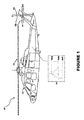
FIG. 1 shows an aircraft with the ice protection system installed on its tail rotor.
FIG. 2 shows the blades of the tail rotor and their electrothernnal devices in more detail.
FIG. 3 shows the electrothernnal devices in a flattened form.
FIG. 4 and FIGS. 4A-4C show electrical wiring, loads, paths, and passes of the ice protection system.
FIG. 5 and FIGS. 5A-5C show heater arrangements within the ice protection system.
DESCRIPTION
Referring now to the drawings, and initially to FIG. 1, a rotory-wing aircraft 10 (e.g., a helicopter) is shown. The aircraft 10 can comprises a fuselage 11, a main rotor 20, and a tail rotor 30. The main rotor 20 can be mounted to the fuselage to provide vertical lift and the tail rotor 30 can be mounted to the fuselage to counter torque. The tail rotor 30 has a blade count that is not equal to a multiple of three. In the illustrated aircraft 10, the tail rotor 30 has four blades 31, 32, 33, and 34
The aircraft 10 also comprises an ice protection system 40 for its tail rotor 30 and more particularly the blades 31-34 of the rotor 30. The ice protection system 40 functions electrothermally by converting electrical power into heat. This heat is used to prevent ice from over-accumulating on the rotor blades 31-34 when the aircraft 10 is in flight.
The aircraft 10 further comprises an onboard power system 50 which supplies electrical power to the ice protection system 40. Specifically, the system 50 provides three-phase alternating-current (AC) power (e.g., 115 volts, 400 cycle). The ice protection system (40) receives electric power through an A-phase line 50A, a B-phase line 50B, and a C-phase line 50C.
With the tail rotor 30, as with most constitutions of related ice-susceptible components, it is significant to synchronize ice protection to avoid inter-component weight discrepancies and/or airfoil differences. In other words, for example, deicing (and/or or anti-icing) is performed substantially simultaneously on akin areas of related components. And when using a three-phase power system, such as the system 50, it is important to pull the same load from each phase is equal to prevent a system load imbalance.
Referring now to FIG. 2, the ice protection system 40 includes four electrothermal heating devices 41-44, one for each blade 31-34 of the tail rotor 30. Each heating device 41-44 is divided into heating zones corresponding to certain regions of the respective blade 31-34. In the illustrated embodiment, each device 41-44 has a zone 41P-44P corresponding to the pressure region of the blade, a zone 41L-44L corresponding to its leading-edge region, a zone 41S-44S corresponding to its suction region, and a zone 41T-44T corresponding to its trailing region.
The ice protection system 40 further includes a connection device 45 for electrical connections among the devices 41-44 and to the power system 50. The connection device 45 includes an A-phase connector 45A for connection to the A-phase line 50A of the power system 50, a B-phase connector 45B for connection to the B-phase line 50B of the power system 50, and a C-phase connector 45C for connection to the C-phase line 50C of the power system 50. Although the connection device 45 is schematically shown as a harness board in the drawings, any construction may be used that accommodates the necessary electrical connections.
In FIG. 3, the electrothermal devices 41-44 are drawn in a flattened condition and arranged around the connection device 45. Each electrothermal device 41-44 has four wires w1-w4 electrically extending between it and the connection device 45. For each wire W, a connection pin P electrically connects one end of the wire W to the respective electrothermal device 41/42/43/44 and another connection pin P connects the other end of the wire W to the connection device 45. This minimal number of wires/pins can help eases assembly, simplify installation, and/or eliminate potential failure points of the ice protection system 40.
In FIG. 4, the electrical-path scheme for the ice protection system 40 is schematically shown. Each zone involves an electric load R which converts supplied electrical power into heat which prevents or removes ice accumulation on the relevant blade region. The heat necessary to accomplish such ice protection can vary among regions. For example, the aft pressure and trailing regions will usually require less heat than the leading-edge and suction regions. Accordingly, the electric loads R will differ among different zones of each electrothermal device 41-44.
While electrical loads R will differ by zone within each device 41-44, comparable zones, and especially opposing comparable zones, can have equivalent electric loads R to insure that ice-protection synchronization. For example, the loads of the leading-edge zone 41L and the suction zone 41S of the first electrothermal device 41 are preferably equivalent to the loads of the leading-edge zone 43L and the suction zone 43L of the third electrothermal device 43. And the loads of the leading-edge zone 42L and the suction zone 42S of the second electrothermal device 42 are preferably equivalent to the loads of the leading-edge zone 44L and the suction zone 44L of the fourth electrothermal device 44.
As is best seen by referring additionally to FIG. 4A, electric power supplied through the A-phase connector 45A follows a path from the connector device 45 to the first device 41 (via wire W1 41), back to the connector device 45 (via wire W4 41). The path continues sequentially through the remaining devices 42-44 in the same manner. Specifically, the path goes from the connector device 45 to the second device 42 (via wire W1 42), back to the connector device 45 (via wire W4 42), to the third device 43 (via wire W1 43), back to the connector device 45 (via wire W4 43), to the fourth device 44 (via wire W1 44), and back to the connector device 45 (via wire W4 44). The electric path returns to the power system 50 via the C-phase connector 45C.
The A-phase electric path has two passes in each device 41-44. Specifically, it passes through the trailing zone 41T/42T/43T/44T and then through the pressure zone 41P/42P/43P/44P of each device 41/42/43/44. The combined load RA of the A-phase electrical path is therefore equal to the sum of the loads of the heating elements in the trailing and pressure zones (i.e., R41T+R41P+R42T+R42P+R43T+R43P+R44T+R44P).
As is best seen by referring additionally to FIG. 4B, electric power supplied through the B-phase connector 45B follows a path from the connector device 45 to the third device 43 (via wire W3 43), back to the connector device 45 (via wire W2 43), to the first device 41 (via wire W3 41), back to the connector device 45 (via wire W2 41), and then returns to the power system 50 via connector 45A. The B-phase path passes through the leading-edge zone 43L of the third device 43 and then through its suction zone 43S. And it passes through the leading-edge zone 41L of the first device 41 and then through its suction zone 41S. The combined load RB of the B-phase electrical path is therefore equal to the sum of the loads of the heating elements in the leading-edge and suction zones of the third device 43 and the first device 41 (i.e., R43L+R43S+R41L+R41S).
As is best seen by referring additionally to FIG. 4C, electric power supplied through the C-phase connector 45C follows the same path as the B-phase path, except through the fourth device 44 and the second device 42, and returning to the power system 50 via the connector 45B. The combined load RC of the C-phase electrical path is equal to the heating elements in the leading-edge and suction zones of the fourth device 44 and the second device 42 (i.e., R44L+R44S+R42L+R42S).
Load balancing is accomplished in the ice protection system 40 by the combined load of the A-phase zones (R41T+R41P+R42T+R42P+R43T+R43P+R44T+R44P), a combined load of the B-phase zones (R43L+R43S+R41L+R41S), and a combined load of the C-phase zones (R44L+R44S+R42L+R42S) being approximately equal. This can be achieved by dimensioning the zones and/or arranging the power densities to attain this equality.
As was alluded to above, the pressure zones 41P-44P and the trailing zones 41T-44T require less heat, and thus less load, to achieve adequate ice protection. As such, the corresponding electrical loads R41P-R44P and R41T-R44T can be substantially less than their counterparts in the leading-edge and suction zones. Thus, while the number of A-phase zones is greater than the number of B-phase zones or C-phase zones, the RA load can still be balanced with the RB load and the RC load.
Although the leading-edge zones 41L-44L and the suction zones 41S-44S require more load to achieve adequate ice protection, the responsibility is split between B-phase zones and C-phase zones. And to insure ice-protection synchronization between opposing comparable zones, the B-phase zones occupy the first and third electrothermal devices 41 and 43, while the C-phase zones occupy the second and fourth electrothermal devices 42 and 44. Furthermore, the B-phase zones are connected in series with each other and the C-phase zones are connected in series with each other to further the synchronization cause.
While the drawings show certain phases on certain zones, other organizations are possible and contemplated. The ice protection system 40 can include any phase-to-component layout wherein each electrothermal device 41-44 receives power from two but not three phases, and wherein the combined load RA of the A-phase zones, the combined load RB of the B-phase zones, and the combined load RC of the C-phase zones are approximately equal.
As shown in FIG. 5, the electric loads R can be provided by heating elements wherein resistance is created by a patterned strip 60 of conductive material. (See e.g., U.S. Pat. No. 7,211,772 and/or U.S. Pat. No. 7,763,833.) The pattern includes a plurality of holes arranged so that the electrical path must twist and turn around holes. In other words, there is no straight line corridor for the electrical path to follow.
With such a hole pattern, chinks in the heating element (due to, for example, fatigue or foreign object damage) are much less likely to defeat the electrical path. As a general rule, this robustness increases with the width of the patterned strip 60. The four-wire layout of the electrothermal devices 41-45 make wider strips 60 possible and thus can contribute to the durability of the ice protection system 40. Moreover, the holes pattern can be tailored to meet desired power density requirements, which can prove useful when designing heating elements to achieve the above-discussed equality among phase loads.
As shown in FIGS. 5A-5C, same-phase zones in an electrothermal device 41-44 can be formed from the same sheet of material. Each sheet can include a junction strip 61 for each wire and a junction strip 61 spanning the two sheets 60.
One may now appreciate that the ice protection system 40 can insure ice-protection synchronization and phase-to-phase load balance, while still offering lower package weight, easier assembly steps, simplified installation procedures, reduced problem points, and/or improved durability. While the aircraft 10, the rotor 30, the ice protection system 40, and/or the power system 50 have been shown and described with respect to a certain embodiment or embodiments, other equivalent alterations and modifications will occur to others skilled in the art upon the reading and understanding of this disclosure. For example, while the ice protection system 40 has been discussed with respect to the tail rotor 30 of a helicopter-type aircraft 10, it may be used on any constitution of related ice-susceptible components. The ice protection system 40 can be used on other rotor assemblies on the aircraft 10 (e.g., the main rotor 20), other aircraft designs, non-aircraft vehicles, and/or non-vehicle applications (e.g., wind turbines). And the electric loads R loads R can be provided by suitable heating elements (e.g., wire-based resistors, graphite fabric, etched ribbons, etc.).