US882527A - Process for bleaching and aging flour and other grain products. - Google Patents
Process for bleaching and aging flour and other grain products. Download PDFInfo
- Publication number
- US882527A US882527A US386500A US1907386500A US882527A US 882527 A US882527 A US 882527A US 386500 A US386500 A US 386500A US 1907386500 A US1907386500 A US 1907386500A US 882527 A US882527 A US 882527A
- Authority
- US
- United States
- Prior art keywords
- flour
- bleaching
- grain products
- aging
- gas
- Prior art date
- Legal status (The legal status is an assumption and is not a legal conclusion. Google has not performed a legal analysis and makes no representation as to the accuracy of the status listed.)
- Expired - Lifetime
Links
- 235000013312 flour Nutrition 0.000 title description 24
- 238000004061 bleaching Methods 0.000 title description 8
- 235000011868 grain product Nutrition 0.000 title description 8
- 238000000034 method Methods 0.000 title description 8
- 230000032683 aging Effects 0.000 title description 6
- 239000007789 gas Substances 0.000 description 12
- IJGRMHOSHXDMSA-UHFFFAOYSA-N Atomic nitrogen Chemical compound N#N IJGRMHOSHXDMSA-UHFFFAOYSA-N 0.000 description 6
- 229910052757 nitrogen Inorganic materials 0.000 description 3
- XEEYBQQBJWHFJM-UHFFFAOYSA-N Iron Chemical compound [Fe] XEEYBQQBJWHFJM-UHFFFAOYSA-N 0.000 description 2
- 239000004411 aluminium Substances 0.000 description 2
- XAGFODPZIPBFFR-UHFFFAOYSA-N aluminium Chemical compound [Al] XAGFODPZIPBFFR-UHFFFAOYSA-N 0.000 description 2
- 229910052782 aluminium Inorganic materials 0.000 description 2
- 239000007844 bleaching agent Substances 0.000 description 2
- 239000001257 hydrogen Substances 0.000 description 2
- 229910052739 hydrogen Inorganic materials 0.000 description 2
- 239000000463 material Substances 0.000 description 2
- 239000007787 solid Substances 0.000 description 2
- 241001527902 Aratus Species 0.000 description 1
- RYGMFSIKBFXOCR-UHFFFAOYSA-N Copper Chemical compound [Cu] RYGMFSIKBFXOCR-UHFFFAOYSA-N 0.000 description 1
- UFHFLCQGNIYNRP-UHFFFAOYSA-N Hydrogen Chemical compound [H][H] UFHFLCQGNIYNRP-UHFFFAOYSA-N 0.000 description 1
- CBENFWSGALASAD-UHFFFAOYSA-N Ozone Chemical compound [O-][O+]=O CBENFWSGALASAD-UHFFFAOYSA-N 0.000 description 1
- QAOWNCQODCNURD-UHFFFAOYSA-L Sulfate Chemical compound [O-]S([O-])(=O)=O QAOWNCQODCNURD-UHFFFAOYSA-L 0.000 description 1
- 229920002892 amber Polymers 0.000 description 1
- 238000004458 analytical method Methods 0.000 description 1
- QVGXLLKOCUKJST-UHFFFAOYSA-N atomic oxygen Chemical compound [O] QVGXLLKOCUKJST-UHFFFAOYSA-N 0.000 description 1
- 150000001875 compounds Chemical class 0.000 description 1
- 239000010949 copper Substances 0.000 description 1
- 229910052802 copper Inorganic materials 0.000 description 1
- 238000010586 diagram Methods 0.000 description 1
- 239000011521 glass Substances 0.000 description 1
- 230000005484 gravity Effects 0.000 description 1
- 150000002431 hydrogen Chemical class 0.000 description 1
- 239000004615 ingredient Substances 0.000 description 1
- 238000007689 inspection Methods 0.000 description 1
- 229910052742 iron Inorganic materials 0.000 description 1
- 239000006193 liquid solution Substances 0.000 description 1
- 239000001301 oxygen Substances 0.000 description 1
- 229910052760 oxygen Inorganic materials 0.000 description 1
- 229910052573 porcelain Inorganic materials 0.000 description 1
- 239000011819 refractory material Substances 0.000 description 1
- 230000000630 rising effect Effects 0.000 description 1
- 238000010079 rubber tapping Methods 0.000 description 1
Images
Classifications
-
- A—HUMAN NECESSITIES
- A21—BAKING; EDIBLE DOUGHS
- A21D—TREATMENT OF FLOUR OR DOUGH FOR BAKING, e.g. BY ADDITION OF MATERIALS; BAKING; BAKERY PRODUCTS
- A21D2/00—Treatment of flour or dough by adding materials thereto before or during baking
- A21D2/02—Treatment of flour or dough by adding materials thereto before or during baking by adding inorganic substances
Definitions
- Our invention hasfor its object to rovide an efficient process for bleaching 'an aging flour, or other grain products; and to this end, our invention consists in subjecting the 'flour to nitric oxid gas (NO).
- NO nitric oxid gas
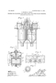
- FIG. 1 is a view chiefly in side elevation, but partly in vertical section, with some portions broken away, illustrating our improved ap aratus.
- Fig. 2 is 'a plan view of the parts sliiown in Fig. 1, with some portions rernoved and others shown in diagram lines only.
- Fig. 3 is a detail showing the flour distributing head detached, in plan view; ⁇ and
- Fig. 4 is -a detail showing the gas generator detached, chiefly in vertical section but with some parts in elevation.
- a suitable skeleton frame 1 Upon a suitable skeleton frame 1 is mountedl a pair of cylindrical mixing vessels 2, closed at their upper ends and having hopperelike bottoms.
- a rotary shaft 3 In each of these vessels 2 is suitably supported a rotary shaft 3, having at its upper end a beveled pinion 4 engaging a bevel gear 5 on countershaft 6.
- Each countershaft 6 is shown as provided with a sprocket wheel 7 connected by a chain 8 with bearing bracket 10 fixed to the walls of the mixing vessel 2, and an upper bracket 11 projecting from a standard 12 rising from the main frame 1, and which also supports the bearings for the shaft 6.
- To the lower end of the shaft 3 To the lower end of the shaft 3 is fixed a screw blade 13 cooperating with the shaft 3 to afford a screw conveyer working in the neck or outlet of the hopper-like bottom of the mixing vessel 2.
- a flour distributing head 14 which, as shown, is of approximately disklike form, its central portion being a solid web and its outer portion being made up of radial fprojections or fingers extending outward r themselves so as to assume somewhat the shape of pro eller blades or paddle arms, as can be readl y understood from an inspection of Figs. 1 and 3.
- the flour is supplied from an overhead source through the main trunk or chute 15, having .a air of diverginlT legs 16, the feet sections of w ich are'verticazl and of cylindrical form, and tap or are secured to the heads of the vessels 2.
- aV weighted valve 17 which may be shifted to throw the flour t0 either of the vessels 2 and shut the same off from the other, whenever so desired.
- a flanged sleeve 18 In the vertical or feet sections of the legs 16 is mounted a flanged sleeve 18 in such a way that it will telescope or move 'freely up and down therein.
- the sleeve 18 is adjustably .supported by a hand screw 19 ta ped through the head of the vessel 2 and ta ring hold of the sleeve flange.
- the shaft 3 passes out through the sleeve 1S and the vertical section of the flour supply leg 16. By adjusting the sleeve 1S up or down, it may be brought nearer to or farther away from the distributing head 14, and thus be made to regulate the flour or feed supply to the mixing 'chamber 2.
- a suitablepcasing 20 adapted to' support the working parts of the gas generator.
- the easing 20 is provided with a door 20u.
- the false bottom 21 is removably mounted on hand screw 22 and adapted to be raised or lowered thereby within the casing 2.0.
- the retort or generating vessel 23 composed of refractory material, such as glass or porcelain.
- Above the generating vessel 23 is a collector 24, shown as removably supported on shelves 24a.
- the collector 24 has a hopperlike bottom adapted to lit within the neck of the generating receptacle 23 and form a tight joint therewith, when the latter is raised to its highest position by the hand screw 22.
- the collector 24 is preferably made of aluminium, but may be made of other suitable material which will not be attacked by the generated gas.
- a main delivery pipe 25 Vhich splits into two branches 26 tapping the respective nii-Xing vessels 2 through the top walls of the saine, as clearly shown in Fig. 1 of the drawings.
- a weighted valve 27 At the junction of the branches 26 with the main pipe 25 is located a weighted valve 27 for directing the gas into either of the vessels v2 and cutting the same .off from the other, whenever so desired.
- An aluminium tube 28 is adjustably sus- As shown, the tube 28 is suspended from the top wall of the collector 24 by means of nuts 29 having screw threaded engagement with the upperV sulfate of copper to the amount of about three per cent. of the liquid solution. Then, when the rod 30 of galvanized iron is submerged in this solution, at its lowerend, the generating action will take place; and the gas will accumulate in the collector 24 and will pass out therefrom through the pipes 25 and 26 into the mixing chambers 2, or one thereof, according to the way in which the valve 27 is set.
- the compounds of nitrogen and oxygen roduced from the materials indicated, are eavier than the air, and hence, the gas will feed by gravity from the pipes 25 and 26 into the mixing chambers 2 and pass down through the latter.
- the Oas supply pipe 26, to the respective mixing c ambers 2 tap the heads of these chambers, at a point above the our distributing head 14. Under the rotary motion of the distributer 14, the
- the 'gas generated rom the ingredients above noted is nitric oxid (NO), and, in view of ⁇ the way in which the generator gets its delivery to the mixing vessels 2, the gas can be delivered into the said -mixing chambers in its substantially generated form, t. e. nitric oxid.
- the flour supply chute sections 15 and 16 are always loaded full of flour, and the outlet from the hopper bottoni, under the action of the screw propeller 13, ⁇ will be loaded full of ⁇ flour, the feed being adjusted properly to .securethis result. It follows that the flour will enter the mixing chambers 2 and pass therethrough with very little (if any) air entering therewith. Hence, itv will further follow that the gas will remain and be applied to the flour inthe form of nitric. oxid or as it was generated at the generator. T ests and analyses, made by an expert chemist, have demonstrated that the nitric oxid is a most el'li'cient form of bleaching agent.
Landscapes
- Chemical & Material Sciences (AREA)
- Inorganic Chemistry (AREA)
- Life Sciences & Earth Sciences (AREA)
- Engineering & Computer Science (AREA)
- Food Science & Technology (AREA)
- Detergent Compositions (AREA)
Description
O1T0.'882,52'7. PATENTED MAR. 1'7, 1908.
.F. MEARS & J. CRAIG. l
PROCESS FOR BLEAOHING'AND AGING PLOUR AND OTHER GRAIN PRODUCTS.
' APPLIOATION FILED JULY s1. 1907.
Tlf 4 UNITED sTATEs rirENT oEEreE.
FRED MEARS,` OF MINNEAPOLIS, AND JOSEPH CRAIG, OF PRINCETON, MINNESOTA, ASSIGN- ORS, BY DIRECT AND MESNE ASSIGNMENTS, TO HYGIENIC PRINCETON, MINNESOTA, A CORPORATION OI*` MINNESOTA.v
REFINER COMPANY, OF
PROCESS FOR BLEACHING AND -AGING FLOUR .AND OTHER GRAIN PRODUCTS.
Patented March 1'?, 1908.
- Original application filed April 27, 1907, Serial No. 370,719. Divided and this application filed July 31, 1907.
` Serial No. 386,500.
To all lwhom 'it 'may 'concer/n:
Be it known that we, FRED MEARs and JOSEPH CRAIG, citizens of th United States, `residing at Minneapolis and Princeton,- respectively, in the counties of Hennepin and Millelacs and State of Minnesota, have invented certain new and useful Im rovements in Processes for Bleaching and lging Flour and other Grain Products; and We do hereby declare the following to be a full, clear, and exact` description of the invention, such as will enable others skilled in the art to which vit appertains to make and use the same.
, Our invention hasfor its object to rovide an efficient process for bleaching 'an aging flour, or other grain products; and to this end, our invention consists in subjecting the 'flour to nitric oxid gas (NO).
'The present case is a division of our ending application S. N. 370,719, filed April 27, 1907, entitled Process and apparatus for I bleaching and aging flour and other. grain products..
AThe accompanying drawings illustrate a suitable apparatus for the successful utilization of our said process, or invention, and
this apparatus is substantially the same as the one disclosed and claimed in our above identified pending application, but differs therefrom in certain details.
In said drawings, wherein like notations refer to like parts throughout the several views :-Figure 1 is a view chiefly in side elevation, but partly in vertical section, with some portions broken away, illustrating our improved ap aratus. Fig. 2 is 'a plan view of the parts sliiown in Fig. 1, with some portions rernoved and others shown in diagram lines only. Fig. 3 is a detail showing the flour distributing head detached, in plan view;` and Fig. 4 is -a detail showing the gas generator detached, chiefly in vertical section but with some parts in elevation.
p Upon a suitable skeleton frame 1 is mountedl a pair of cylindrical mixing vessels 2, closed at their upper ends and having hopperelike bottoms. In each of these vessels 2 is suitably supported a rotary shaft 3, having at its upper end a beveled pinion 4 engaging a bevel gear 5 on countershaft 6. Each countershaft 6 is shown as provided with a sprocket wheel 7 connected by a chain 8 with bearing bracket 10 fixed to the walls of the mixing vessel 2, and an upper bracket 11 projecting from a standard 12 rising from the main frame 1, and which also supports the bearings for the shaft 6. To the lower end of the shaft 3 is fixed a screw blade 13 cooperating with the shaft 3 to afford a screw conveyer working in the neck or outlet of the hopper-like bottom of the mixing vessel 2. To t e shaft 3, within the vessel 2, at a suitable oint below the head or upper end of the vesseli 2, is located a flour distributing head 14 which, as shown, is of approximately disklike form, its central portion being a solid web and its outer portion being made up of radial fprojections or fingers extending outward r themselves so as to assume somewhat the shape of pro eller blades or paddle arms, as can be readl y understood from an inspection of Figs. 1 and 3. The flour is supplied from an overhead source through the main trunk or chute 15, having .a air of diverginlT legs 16, the feet sections of w ich are'verticazl and of cylindrical form, and tap or are secured to the heads of the vessels 2. At the point .where the legs 16 diverge from the trunk 15, is located aV weighted valve 17 which may be shifted to throw the flour t0 either of the vessels 2 and shut the same off from the other, whenever so desired. In the vertical or feet sections of the legs 16 is mounted a flanged sleeve 18 in such a way that it will telescope or move 'freely up and down therein. The sleeve 18 is adjustably .supported by a hand screw 19 ta ped through the head of the vessel 2 and ta ring hold of the sleeve flange. The shaft 3 passes out through the sleeve 1S and the vertical section of the flour supply leg 16. By adjusting the sleeve 1S up or down, it may be brought nearer to or farther away from the distributing head 14, and thus be made to regulate the flour or feed supply to the mixing 'chamber 2.-
On the top ofithe frame 1 is mounted a suitablepcasing 20 adapted to' support the working parts of the gas generator. As shown, the easing 20 is provided with a door 20u.
om the solid web, and bent upon 4pended within the generator.
and a false bottom 21 mounted on hand screw 22 and adapted to be raised or lowered thereby within the casing 2.0. On the false bottom 21'is removably mounted the retort or generating vessel 23 composed of refractory material, such as glass or porcelain. Above the generating vessel 23 is a collector 24, shown as removably supported on shelves 24a. The collector 24 has a hopperlike bottom adapted to lit within the neck of the generating receptacle 23 and form a tight joint therewith, when the latter is raised to its highest position by the hand screw 22. The collector 24 is preferably made of aluminium, but may be made of other suitable material which will not be attacked by the generated gas. From one end of the collector 24 extends a main delivery pipe 25 Vhich splits into two branches 26 tapping the respective nii-Xing vessels 2 through the top walls of the saine, as clearly shown in Fig. 1 of the drawings. At the junction of the branches 26 with the main pipe 25 is located a weighted valve 27 for directing the gas into either of the vessels v2 and cutting the same .off from the other, whenever so desired.
An aluminium tube 28 is adjustably sus- As shown, the tube 28 is suspended from the top wall of the collector 24 by means of nuts 29 having screw threaded engagement with the upperV sulfate of copper to the amount of about three per cent. of the liquid solution. Then, when the rod 30 of galvanized iron is submerged in this solution, at its lowerend, the generating action will take place; and the gas will accumulate in the collector 24 and will pass out therefrom through the pipes 25 and 26 into the mixing chambers 2, or one thereof, according to the way in which the valve 27 is set. The compounds of nitrogen and oxygen roduced from the materials indicated, are eavier than the air, and hence, the gas will feed by gravity from the pipes 25 and 26 into the mixing chambers 2 and pass down through the latter. The Oas supply pipe 26, to the respective mixing c ambers 2, tap the heads of these chambers, at a point above the our distributing head 14. Under the rotary motion of the distributer 14, the
flour falling. thereon', through the sleeve 18, will be' thrown off from the distributer in the form of a shower, orv in a finely divided condition, well ad aptiiig the gas, entering through the pipe 26, to get directly at all the different articles of. the flour. The 'gas generated rom the ingredients above noted is nitric oxid (NO), and, in view of `the way in which the generator gets its delivery to the mixing vessels 2, the gas can be delivered into the said -mixing chambers in its substantially generated form, t. e. nitric oxid. The flour supply chute sections 15 and 16 are always loaded full of flour, and the outlet from the hopper bottoni, under the action of the screw propeller 13, `will be loaded full of` flour, the feed being adjusted properly to .securethis result. It follows that the flour will enter the mixing chambers 2 and pass therethrough with very little (if any) air entering therewith. Hence, itv will further follow that the gas will remain and be applied to the flour inthe form of nitric. oxid or as it was generated at the generator. T ests and analyses, made by an expert chemist, have demonstrated that the nitric oxid is a most el'li'cient form of bleaching agent.
So far as weknow, we are the first to have treated flour, or other grain products, with nitric oxid. All bleaching and aging apparatus disclosed in the prior art, so far as nown to us, delivers to the flour peroxid of,
nitrogen, or peroxid of nitrogen eonimingled with more or less peroxid of hydrogen, or ozone with peroxid of hydrogen.
the use of nitric oxid alone, a bleaching takes place in much less time or, put it another way, with much less gas per unit of flour as Our commercial usage has demonstrated that, with.
compared with any of the processes hitherto proposed in the rior art.
While especia ly designed for bleaching and aging flour, it must be understood that the invention is `applicable to bleach andage oth er grain products, when in a finely divided or commiiiuted condition 5 and, in the claims,
the word flour is used in its broad. or
FRED MEARS. JOSEPH CRAIG.
Witnesses:
JAS. F. .WILLIAMSON HARRY D. KILGORE.
Priority Applications (1)
| Application Number | Priority Date | Filing Date | Title |
|---|---|---|---|
| US386500A US882527A (en) | 1907-04-27 | 1907-07-31 | Process for bleaching and aging flour and other grain products. |
Applications Claiming Priority (2)
| Application Number | Priority Date | Filing Date | Title |
|---|---|---|---|
| US37071907A US882526A (en) | 1907-04-27 | 1907-04-27 | Apparatus for bleaching and aging flour and other grain products. |
| US386500A US882527A (en) | 1907-04-27 | 1907-07-31 | Process for bleaching and aging flour and other grain products. |
Publications (1)
| Publication Number | Publication Date |
|---|---|
| US882527A true US882527A (en) | 1908-03-17 |
Family
ID=2950966
Family Applications (1)
| Application Number | Title | Priority Date | Filing Date |
|---|---|---|---|
| US386500A Expired - Lifetime US882527A (en) | 1907-04-27 | 1907-07-31 | Process for bleaching and aging flour and other grain products. |
Country Status (1)
| Country | Link |
|---|---|
| US (1) | US882527A (en) |
-
1907
- 1907-07-31 US US386500A patent/US882527A/en not_active Expired - Lifetime
Similar Documents
| Publication | Publication Date | Title |
|---|---|---|
| US3700468A (en) | Sterilizing separate compartments of particulate material | |
| US1030271A (en) | Feed and distributing means for separators. | |
| US882526A (en) | Apparatus for bleaching and aging flour and other grain products. | |
| US1478337A (en) | Method of treating solutions to obtain solid constituents thereof separated in a coarse condition | |
| US4480924A (en) | Stirrer-mixer for retorts in particular, wherein the insuffation is carried out through the stirrer itself | |
| US1505517A (en) | Process of activating carbon | |
| TW201304883A (en) | Rotating spray apparatus | |
| US697272A (en) | Method of blanching peas, &c. | |
| GB190927602A (en) | Improvements in Apparatus for Cleaning and Boiling Fruit and the like. | |
| US1062445A (en) | Gas-cleaner. | |
| US1006162A (en) | Continuous-process cooker. | |
| US1391953A (en) | Method of treating canned foods | |
| US1959731A (en) | Process of uninterruptedly carrying out the precipitation of heavy metallic azids particularly silver and lead-azid | |
| US512232A (en) | Corn-cooking machine | |
| US1376567A (en) | Fuel feeding and distributing device for gas-producers | |
| US1148364A (en) | Acetylene-gas generator. | |
| US1739149A (en) | Mixing mill | |
| US1893777A (en) | Production of cases from carbides and water | |
| US683470A (en) | Acetylene-gas generator. | |
| US386363A (en) | Plant for the manufacture of starch from grain | |
| US829212A (en) | Apparatus for processing canned food. | |
| US1427269A (en) | Lyeing section of peeling machines | |
| US394601A (en) | Apparatus for malting | |
| US105688A (en) | Improvement in apparatus for removing oil from seeds, meal | |
| US930749A (en) | Gas-generator. |