US8825167B2 - Device and method for auditory stimulation - Google Patents
Device and method for auditory stimulation Download PDFInfo
- Publication number
- US8825167B2 US8825167B2 US13/796,422 US201313796422A US8825167B2 US 8825167 B2 US8825167 B2 US 8825167B2 US 201313796422 A US201313796422 A US 201313796422A US 8825167 B2 US8825167 B2 US 8825167B2
- Authority
- US
- United States
- Prior art keywords
- measurement signal
- patient
- acoustic
- stimulation
- acoustic stimulation
- Prior art date
- Legal status (The legal status is an assumption and is not a legal conclusion. Google has not performed a legal analysis and makes no representation as to the accuracy of the status listed.)
- Active
Links
Images


Classifications
-
- A—HUMAN NECESSITIES
- A61—MEDICAL OR VETERINARY SCIENCE; HYGIENE
- A61H—PHYSICAL THERAPY APPARATUS, e.g. DEVICES FOR LOCATING OR STIMULATING REFLEX POINTS IN THE BODY; ARTIFICIAL RESPIRATION; MASSAGE; BATHING DEVICES FOR SPECIAL THERAPEUTIC OR HYGIENIC PURPOSES OR SPECIFIC PARTS OF THE BODY
- A61H23/00—Percussion or vibration massage, e.g. using supersonic vibration; Suction-vibration massage; Massage with moving diaphragms
-
- A—HUMAN NECESSITIES
- A61—MEDICAL OR VETERINARY SCIENCE; HYGIENE
- A61B—DIAGNOSIS; SURGERY; IDENTIFICATION
- A61B5/00—Measuring for diagnostic purposes; Identification of persons
- A61B5/48—Other medical applications
- A61B5/486—Bio-feedback
-
- A—HUMAN NECESSITIES
- A61—MEDICAL OR VETERINARY SCIENCE; HYGIENE
- A61F—FILTERS IMPLANTABLE INTO BLOOD VESSELS; PROSTHESES; DEVICES PROVIDING PATENCY TO, OR PREVENTING COLLAPSING OF, TUBULAR STRUCTURES OF THE BODY, e.g. STENTS; ORTHOPAEDIC, NURSING OR CONTRACEPTIVE DEVICES; FOMENTATION; TREATMENT OR PROTECTION OF EYES OR EARS; BANDAGES, DRESSINGS OR ABSORBENT PADS; FIRST-AID KITS
- A61F11/00—Methods or devices for treatment of the ears or hearing sense; Non-electric hearing aids; Methods or devices for enabling ear patients to achieve auditory perception through physiological senses other than hearing sense; Protective devices for the ears, carried on the body or in the hand
-
- A—HUMAN NECESSITIES
- A61—MEDICAL OR VETERINARY SCIENCE; HYGIENE
- A61H—PHYSICAL THERAPY APPARATUS, e.g. DEVICES FOR LOCATING OR STIMULATING REFLEX POINTS IN THE BODY; ARTIFICIAL RESPIRATION; MASSAGE; BATHING DEVICES FOR SPECIAL THERAPEUTIC OR HYGIENIC PURPOSES OR SPECIFIC PARTS OF THE BODY
- A61H1/00—Apparatus for passive exercising; Vibrating apparatus ; Chiropractic devices, e.g. body impacting devices, external devices for briefly extending or aligning unbroken bones
-
- A—HUMAN NECESSITIES
- A61—MEDICAL OR VETERINARY SCIENCE; HYGIENE
- A61M—DEVICES FOR INTRODUCING MEDIA INTO, OR ONTO, THE BODY; DEVICES FOR TRANSDUCING BODY MEDIA OR FOR TAKING MEDIA FROM THE BODY; DEVICES FOR PRODUCING OR ENDING SLEEP OR STUPOR
- A61M21/00—Other devices or methods to cause a change in the state of consciousness; Devices for producing or ending sleep by mechanical, optical, or acoustical means, e.g. for hypnosis
-
- A—HUMAN NECESSITIES
- A61—MEDICAL OR VETERINARY SCIENCE; HYGIENE
- A61H—PHYSICAL THERAPY APPARATUS, e.g. DEVICES FOR LOCATING OR STIMULATING REFLEX POINTS IN THE BODY; ARTIFICIAL RESPIRATION; MASSAGE; BATHING DEVICES FOR SPECIAL THERAPEUTIC OR HYGIENIC PURPOSES OR SPECIFIC PARTS OF THE BODY
- A61H2201/00—Characteristics of apparatus not provided for in the preceding codes
- A61H2201/50—Control means thereof
- A61H2201/5005—Control means thereof for controlling frequency distribution, modulation or interference of a driving signal
-
- A—HUMAN NECESSITIES
- A61—MEDICAL OR VETERINARY SCIENCE; HYGIENE
- A61H—PHYSICAL THERAPY APPARATUS, e.g. DEVICES FOR LOCATING OR STIMULATING REFLEX POINTS IN THE BODY; ARTIFICIAL RESPIRATION; MASSAGE; BATHING DEVICES FOR SPECIAL THERAPEUTIC OR HYGIENIC PURPOSES OR SPECIFIC PARTS OF THE BODY
- A61H2205/00—Devices for specific parts of the body
- A61H2205/02—Head
-
- A—HUMAN NECESSITIES
- A61—MEDICAL OR VETERINARY SCIENCE; HYGIENE
- A61M—DEVICES FOR INTRODUCING MEDIA INTO, OR ONTO, THE BODY; DEVICES FOR TRANSDUCING BODY MEDIA OR FOR TAKING MEDIA FROM THE BODY; DEVICES FOR PRODUCING OR ENDING SLEEP OR STUPOR
- A61M21/00—Other devices or methods to cause a change in the state of consciousness; Devices for producing or ending sleep by mechanical, optical, or acoustical means, e.g. for hypnosis
- A61M2021/0005—Other devices or methods to cause a change in the state of consciousness; Devices for producing or ending sleep by mechanical, optical, or acoustical means, e.g. for hypnosis by the use of a particular sense, or stimulus
- A61M2021/0027—Other devices or methods to cause a change in the state of consciousness; Devices for producing or ending sleep by mechanical, optical, or acoustical means, e.g. for hypnosis by the use of a particular sense, or stimulus by the hearing sense
Definitions
- Tinnitus is such a disease Tinnitus refers to a sound in the ear, mostly in the form of a high-pitched tone, but occasionally also having a knocking, pulsing or beating character. It is a widespread disease in the form of disturbing sensations that are of an agonizing nature for many patients.
- therapy methods for such diseases include pharmacotherapy, deep brain stimulation and the like.
- the present application is directed to a device and method for desynchronizing a patient's neuronal brain activity involving a neuron population firing in a pathologically synchronized manner.
- the device includes a stimulation unit configured to generate an acoustic stimulation signal to stimulate the neuron population when the acoustic stimulation signal is aurally received by the patient.
- the acoustic stimulation signal has a first frequency and a second frequency, with the first frequency provided to reset the phase of the neuronal brain activity in a first sub-population of the stimulated neuron population, and the second frequency provided to reset the phase of the neuronal brain activity in a second sub-population of the stimulated neuron population.
- a device for desynchronizing a patient's neuronal brain activity involving a neuron population firing in a pathologically synchronized manner.
- the device includes a stimulation unit to generate an acoustic stimulation signal to stimulate the neuron population when the acoustic stimulation signal is aurally received by the patient; a measurement unit to record a measurement signal on a patient, which measurement signal reproduces the neuronal activity in the auditory cortex of the patient or a region connected thereto; and a control unit to actuate the stimulation unit based on the measurement signal such that the stimulation unit converts the measurement signal into the acoustic stimulation signal.
- a method for desynchronizing a patient's neuronal brain activity involving a neuron population firing in a pathologically synchronized manner, the method including generating an acoustic stimulation signal to stimulate the neuron population when the acoustic stimulation signal is aurally received by the patient, the acoustic stimulation signal having at least a first frequency and a second frequency; setting the first frequency to reset the phase of the neuronal brain activity in a first sub-population of the stimulated neuron population; and setting the second frequency to reset the phase of the neuronal activity in a second sub-population of the stimulated neuron population.
- a method for desynchronizing a patient's neuronal brain activity involving a neuron population firing in a pathologically synchronized manner.
- the method includes recording a measurement signal on a patient, which measurement signal reproduces the neuronal activity in the auditory cortex or a region connected thereto; converting the measurement signal into an acoustic stimulation signal; and generating the acoustic stimulation signal to stimulate the neuron population when the acoustic stimulation signal is aurally received by the patient.
- FIG. 1 shows a schematic illustration of a device 100 as per an exemplary embodiment.
- FIG. 2 shows an illustration of sinusoidal oscillations at the frequencies of f 1 , f 2 , f 3 and f 4 as per an exemplary embodiment.
- FIG. 3 shows an illustration of a sinusoidal oscillation amplitude-modulated by a rectangular function as per an exemplary embodiment.
- FIG. 4 shows a schematic illustration of a device 400 as per a further exemplary embodiment.
- FIG. 5 shows a schematic illustration of a device 500 as per a further exemplary embodiment.
- FIG. 6 shows a schematic illustration of a device 600 as per a further exemplary embodiment.
- FIG. 7 shows a schematic illustration of a device 700 as per a further exemplary embodiment.
- FIG. 8 shows a schematic illustration of a device 800 as per a further exemplary embodiment.
- FIG. 9 shows a schematic illustration of a device 900 as per a further exemplary embodiment.
- FIG. 10 shows a schematic illustration of an auditory stimulation method as per an exemplary embodiment.
- FIG. 11 shows a schematic illustration of a further auditory stimulation method as per an exemplary embodiment.
- FIG. 12 shows a schematic illustration of a further auditory stimulation method as per an exemplary embodiment.
- FIG. 13 shows a schematic illustration of a further auditory stimulation method as per an exemplary embodiment.
- FIG. 14 shows a schematic illustration of a further auditory stimulation method as per an exemplary embodiment.
- FIGS. 15A and 15B show schematic illustrations of the generation of modulation signals as per an exemplary embodiment.
- FIG. 1 illustrates in a schematic fashion a device 100 , which consists of a control unit 10 and a stimulation unit 11 connected to the control unit 10 .
- FIG. 1 furthermore illustrates an ear 12 of a patient and the auditory cortex 13 in the brain of the patient in a schematic fashion.
- the stimulation unit 11 is actuated by the control unit 10 by means of one or more control signals 14 during the operation of the device 100 , and the stimulation unit 11 generates one or more acoustic stimulation signals 15 with the aid of the control signal 14 .
- the frequency spectrum of the acoustic stimulation signal 15 may lie completely or partly in the range audible to a human.
- the acoustic stimulation signal 15 is taken in by the patient by one or both ears 12 and is transmitted to neuron populations in the brain via the cochlear nerve or nerves 16 .
- the acoustic stimulation signal 15 is developed such that it stimulates neuron populations in the auditory cortex 13 .
- At least a first frequency f 1 and a second frequency f 2 are present in the frequency spectrum of the acoustic stimulation signal 15 .
- the acoustic stimulation signal 15 can furthermore contain additional frequencies or frequency mixtures; in the exemplary embodiment shown in FIG. 2 , these are a third frequency f 3 and a fourth frequency f 4 .
- the device 100 can be used in particular for treating neurological or psychiatric diseases, such as tinnitus, migraine, headaches of different form and genesis (e.g. cluster headache), trigeminal neuralgia, sleep disorders, neuralgias and headaches in the case of neuroborreliosis, attention deficit syndrome (ADS), attention deficit hyperactivity syndrome (ADHS), neuroses, compulsion neuroses, depressions, mania, schizophrenia, tumors, arrhythmias, addiction diseases, bruxism (nocturnal teeth grinding), eating disorders, and the like.
- neurological or psychiatric diseases such as tinnitus, migraine, headaches of different form and genesis (e.g. cluster headache), trigeminal neuralgia, sleep disorders, neuralgias and headaches in the case of neuroborreliosis, attention deficit syndrome (ADS), attention deficit hyperactivity syndrome (ADHS), neuroses, compulsion neuroses, depressions, mania, schizophrenia, tumors, arrhythmias, addiction diseases,
- the aforementioned diseases can be caused by a disorder in the bioelectric communication of neural networks connected in specific circuits.
- a neuron population continuously generates pathological neuronal activity and possibly a pathological connectivity (network structure) associated therewith.
- a large number of neurons form action potentials at the same time, i.e. the involved neurons fire in an overly synchronous fashion.
- the sick neuron population exhibits an oscillatory neuronal activity, i.e. the neurons fire rhythmically.
- the mean frequency of the pathological rhythmic activity of the affected neural networks lies approximately in the range between 1 and 30 Hz, but it can also lie outside of this range.
- the neurons fire qualitatively differently in healthy humans, e.g. in an uncontrolled fashion.
- the acoustic stimulation signal 15 generated by the stimulation unit 11 is converted into nerve impulses in the inner ear and transmitted to the auditory cortex 13 via the cochlear nerve 16 .
- the tonotopic arrangement of the auditory cortex 13 means that a particular part of the auditory cortex 13 is activated in the case of the acoustic stimulation of the inner ear with a particular frequency.
- the tonotopic arrangement of the auditory cortex is described, for example, in the following articles: “Tonotopic organization of the human auditory cortex as detected by BOLD-FMRI” by D. Bilecen, K. Scheffler, N. Schmid, K. Tschopp and J.
- the acoustic stimulation signal 15 is developed such that it stimulates a neuron population in the auditory cortex 13 with a pathologically synchronous and oscillatory activity.
- this neuron population can at least be thought of being subdivided into various sub-populations, inter alia the sub-populations 17 , 18 , 19 and 20 shown in FIG. 1 .
- the neurons of all sub-populations 17 to 20 for the most part fire synchronously and on average with the same pathological frequency.
- the first sub-population 17 is stimulated by means of the first frequency f 1
- the second sub-population 18 is stimulated by means of the second frequency f 2
- the third sub-population 19 is stimulated by means of the third frequency f 3
- the fourth sub-population 20 is stimulated by means of the fourth frequency f 4 .
- the stimulation by the acoustic stimulation signal 15 brings about a resetting, a so-called reset, of the phase of the neuronal activity in the stimulated neurons in the respective sub-populations 17 to 20 .
- the reset sets the phase of the stimulated neurons to a certain phase value, e.g. 0°, independently of the current phase value.
- the phase of the neuronal activity of the pathological sub-populations 17 to 20 is controlled by means of a targeted stimulation.
- the pathological neuron population can be stimulated in a targeted fashion at the different sites 17 to 20 as a result of the tonotopic arrangement of the auditory cortex 13 and the plurality of frequencies f 1 to f 4 contained in the acoustic stimulation signal 15 .
- each of the sub-populations 17 to 20 the neurons are still synchronous and also on average still fire with the same pathological frequency, but each of the sub-populations 17 to 20 has the phase in respect of its neuronal activity that was imposed on it by the stimulation stimulus with the associated frequency f 1 to f 4 .
- the state with at least two sub-populations, which state was generated by the stimulation is unstable and the entire neuron population quickly approaches a state of complete desynchronization, in which the neurons fire in an uncorrelated fashion.
- the desired state, i.e. the complete desynchronization thus is not available immediately after the application of the acoustic stimulation signal 15 via the stimulation unit 11 , but usually sets in within a few periods or even within less than one period of the pathological activity.
- the stimulation with the device 100 can obtain a reorganization of the connectivity of the dysfunctional neural networks and so long-lasting therapeutic effects can be brought about, which last significantly longer than the acoustic stimulation.
- the strength of the stimulus of the respective area in the auditory cortex 13 generated by the respective sinusoidal oscillation corresponds to the amplitude of the respective sinusoidal oscillation.
- FIG. 3 The generation of the pulsed sinusoidal oscillations shown in FIG. 2 is illustrated in FIG. 3 in an exemplary fashion.
- a sinusoidal oscillation 21 is multiplied by a rectangular function 22 , which can for example assume the values 0 or 1.
- the rectangular function 22 At the times at which the rectangular function 22 has a value of 0 the associated stimulus is switched off and while the rectangular function 22 equals 1 the stimulus is switched on.
- the sinusoidal oscillation 21 can be multiplied by any other function instead of the rectangular function 22 . As a result this multiplication corresponds to an amplitude modulation of the sinusoidal oscillation 21 .
- a less focal stimulation that activates relatively large parts of the auditory cortex 13 is intended to be carried out instead of a focal stimulation, frequency mixtures are applied, e.g. in a pulsed fashion, instead of individual frequencies.
- frequency mixtures are applied, e.g. in a pulsed fashion, instead of individual frequencies.
- Using a frequency mixture bounded between a lower frequency f lower and an upper frequency f upper stimulates all those parts of the auditory cortex 13 that are stimulated by the frequencies between f lower and f upper due to the tonotopic arrangement.
- the four associated frequency mixtures with the boundaries f j lower and f j upper are applied at the desired times.
- the device 100 can be operated in a so-called “open-loop” mode, in which the control unit 10 actuates the stimulation unit 11 such that the latter generates prescribed acoustic stimulation signals 15 during a defined stimulation time (e.g. over a plurality of hours).
- the device 100 can also be developed to form a device 400 shown in FIG. 4 , the latter device constituting a so-called “closed-loop” system.
- the device 400 also contains a measurement unit 23 , which provides one or more measurement signals 24 recorded on the patient and transmits said signals to the control unit 10 .
- the measurement unit 23 can involve non-invasive sensors, such as electroencephalography (EEG) electrodes, magnetoencephalography (MEG) sensors, accelerometers, electromyography (EMG) electrodes and sensors for determining blood pressure, respiration or skin resistance.
- EEG electroencephalography
- MEG magnetoencephalography
- EMG electromyography
- the measurement unit 23 in the form of one or more sensors can be implanted into the body of the patient.
- epicortical, intracortical or subcutaneous electrodes can be used as invasive sensors.
- the measurement unit 23 can be used to measure the physiological activity in the stimulated target region or in a region connected therewith.
- control unit 10 can perform a demand-driven stimulation.
- control unit 10 detects the presence and/or the development of one or more pathological features on the basis of the measurement signals 24 recorded by the measurement unit 23 .
- the amplitude or the magnitude of the neuronal activity can be measured and compared to a predetermined threshold.
- the control unit 10 can be configured such that stimulation of one or more target areas in the auditory cortex is initiated as soon as the prescribed threshold is exceeded.
- parameters of the acoustic stimulation signals 15 can be set by the control unit 10 on the basis of the development of the pathological features.
- one or more thresholds can be prescribed, and if the amplitude or the magnitude of the measurement signals 24 exceeds or drops below a certain threshold, the control unit 10 varies a particular parameter of the acoustic stimulation signal 15 , such as the amplitude of one or more sinusoidal oscillations from which the acoustic stimulation signal 15 is composed.
- the measurement signals 24 recorded by the measurement unit 23 can be converted directly or if need be after one or more processing steps into acoustic stimulation signals 15 and to be applied by the stimulation unit 11 .
- the measurement signals 24 amplified and if need be after mathematical combination (e.g. after mixing the measurement signals) with a time delay and linear and/or nonlinear combination steps, can be fed as control signals into the control input of the stimulation unit 11 .
- the combination mode is selected such that the pathological neuronal activity is counteracted and the acoustic stimulation signals 15 likewise disappear or are at least significantly reduced in strength (amplitude) as the pathological neuronal activity reduces.
- FIG. 5 schematically illustrates a device 500 that constitutes a development of the device 100 shown in FIG. 1 .
- the device 500 does not use any signal measured by a sensor for the demand-driven variation of the stimulation.
- a sound generator (loudspeaker) is used as a stimulation unit 11 in the device 500 , which sound generator is surrounded by an earplug 30 .
- the earplug 30 is inserted into the outer auditory canal of an ear 12 of the patient and attached to the ear 12 with or without a holder or another suitable mechanical aid.
- the control unit 10 which actuates the sound generator, and also a battery or a rechargeable battery for supplying the electrical components of the device 500 with current can be housed in one or more separate units 31 .
- the unit 31 can be connected to the earplug 30 by means of a mechanical fastener, e.g. a holder.
- a connection cable 32 connects the earplug 30 to the control unit 10 and the battery.
- headphones containing the control unit 10 and the battery can also be used instead of the earplug 30 .
- the device 500 can be switched on by the patient by means of an operating unit (e.g. switch-on button and/or control dial), which is attached either to the unit 31 or directly to the earplug 30 .
- the control dial can be used, for example, to set the maximum stimulation strength.
- the device 500 can comprise a control medium 33 , which for example is connected to the control unit 10 in a telemetric fashion (e.g. by radio waves) or by means of a connection cable. In the case of a cabled connection, plug-in connections can be used for connection and disconnection.
- the device 500 can also comprise an additional control medium (not illustrated) operable by e.g. the medical practitioner, which control medium is connected to the control unit 10 in a telemetric fashion or by means of a connection cable.
- control medium operable by e.g. the medical practitioner, which control medium is connected to the control unit 10 in a telemetric fashion or by means of a connection cable.
- plug-in connections can be used for connection and disconnection.
- one or more sensors such as, EEG electrodes or an accelerometer or the like, can be provided for registering and/or documenting the stimulation success or for the examination by the medical practitioner.
- FIGS. 6 to 9 schematically illustrate devices 600 , 700 , 800 and 900 as developments of the device 400 .
- the devices 600 to 900 in each case comprise a measurement unit 23 , by means of which demand-driven control can be performed and/or the measurement signals 24 can be fed back into the stimulation unit 11 .
- the devices 600 and 700 constitute non-invasive variants, while the devices 800 and 900 are partly implanted into the body of the patient.
- the devices 600 to 900 comprise an earplug 30 or headphones with a sound generator.
- the device 600 illustrated in FIG. 6 comprises epicutaneous, i.e. attached to the skin of the patient, EEG electrodes 34 that are connected to the control unit 10 in the unit 31 via connection cables 35 , 36 .
- the control unit 10 amplifies the potential difference measured by means of the EEG electrodes 34 and uses said potential difference for actuating the sound generator in the earplug 30 after an optional linear or nonlinear combination.
- the EEG electrodes 34 can also be connected wirelessly, i.e. telemetrically, to the control unit 10 . The advantage of this is that the patient is not impeded by connection cables and can not be caught in obstacles, for example.
- the device 700 illustrated in FIG. 7 has an accelerometer 37 as a measurement unit instead of an EEG electrode.
- the accelerometer 37 is attached, like a watch, to a limb of the patient that trembles due to disease.
- the acceleration signals recorded by the accelerometer 37 are amplified in the control unit 10 and are used for actuating the sound generator in the earplug 30 after an optional linear or nonlinear combination.
- the accelerometer 37 can be connected to the control unit 10 in a telemetric fashion or by means of a connection cable.
- FIG. 8 shows an invasive variant.
- the device 800 comprises one or more subcutaneously implanted electrodes 38 as a measurement unit, a connection cable 39 and a transmission and reception unit 40 , which are implanted into the body of the patient under the scalp 41 and outside of the bony skull 42 . Outside of the body of the patient there is a transmission and reception unit 43 , which is connected to the unit 31 and the control unit 10 situated therein via a connection cable 44 .
- the measurement signals 24 recorded by the electrode 38 are transmitted to the control unit 10 via the transmission and reception units 40 and 43 , which for example are each implemented as a coil and which allow the wireless and bidirectional transmission of signals and electrical power therebetween.
- the potential differences measured by the electrode 38 are amplified in the control unit 10 and are used for actuating the sound generator integrated into the earplug 30 after an optional linear or nonlinear combination.
- FIG. 9 A further invasive variant is illustrated schematically in FIG. 9 .
- One or more epicortically implanted electrodes 45 serve as a measurement unit in the device 900 shown therein.
- “epicortical” means “situated on the cerebral cortex.”
- the cerebral cortex 46 , 47 of both hemispheres is shown schematically for illustrative purposes.
- the control unit 10 amplifies the potential difference measured by means of the epicortically implanted electrode 45 and uses said potential difference for actuating the sound generator in the earplug 30 after an optional linear or nonlinear combination.
- the epicortical electrode 45 shown in FIG. 9 can for example also be replaced by an intracortical electrode (not illustrated).
- the measurement signals recorded by the differently developed measurement units 23 i.e. the EEG-electrodes 34 , the accelerometer 37 or the electrodes 38 or 45 , can be used for feed-back control, as will be described in still more detail further below, and in one embodiment can be fed into the sound generator as actuation signals.
- demand-driven control can be carried out on the basis of the measurement signals 24 .
- certain parameters of the stimulation method such as the stimulation strength or the stimulation duration, can be set with the aid of the measurement signals 24 . This type of demand-driven control will be explained in still more detail further below in conjunction with FIGS. 10 to 12 .
- the four frequencies f 1 to f 4 are intended to be used below to explain in an exemplary fashion as to how a time-offset reset of the phases of the neuronal activity of sub-populations of a pathologically synchronous and oscillatory neuron population can achieve a desynchronization of the entire neuron population.
- the four frequencies f 1 to f 4 should merely be understood as exemplary, and it should be understood that any other number of frequencies or frequency mixtures can be used for stimulation purposes.
- the frequencies f 1 to f 4 have been selected such that they in each case stimulate particular regions 17 to 20 of the auditory cortex 13 . This affords the above-described subdivision of a pathological neuron population into sub-populations 17 to 20 .
- the frequencies f 1 to f 4 can for example be applied with a time offset.
- FIG. 10 A stimulation method that is suitable for the above-described purposes and can for example be performed by one of the devices 100 to 900 is illustrated schematically in FIG. 10 .
- the upper four rows of FIG. 10 plot, one below the other, four sinusoidal oscillations with frequencies f 1 , f 2 , f 3 and f 4 over time t.
- the acoustic stimulation signal 15 is formed from the illustrated sinusoidal oscillations.
- the four sinusoidal oscillations have been multiplied by rectangular functions for generating pulsed sinusoidal oscillations. Each sinusoidal oscillation pulse is repeated periodically with a frequency f stim .
- Such sequences of pulsed sinusoidal oscillations are suitable for resetting the neuronal phase of the respectively stimulated pathological neuron sub-population 17 , 18 , 19 or 20 if said oscillations are applied as acoustic stimulation signals 15 .
- the phase reset does not necessarily already result after one or a few pulses, but a certain number of the sinusoidal oscillation pulses shown in FIG. 10 may be required to reset the neuronal phase of the respective sub-population 17 , 18 , 19 or 20 .
- the frequency f stim can lie in the vicinity of the mean frequency of the pathologically rhythmic activity of the target network.
- the mean frequency typically lies in the range between 1 and 30 Hz, but it can also lie outside of this range as noted above.
- the frequency range between 1.5 and 4 Hz.
- the frequency at which the pathological neurons fire synchronously is usually not constant, but can by all means have variations and moreover has individual deviations in each patient.
- the mean peak frequency of the pathological rhythmic activity of the patient can for example be determined in order to calculate the frequency f stim .
- This peak frequency can then be used as stimulation frequency f stim , or else be varied, for example in a range between f stim ⁇ 3 Hz and f stim +3 Hz.
- a frequency f stim it is also possible for a frequency f stim to be selected in the range between 1 and 30 Hz without a preceding measurement and this frequency can for example be varied during the stimulation until the frequency f stim is found, by means of which the best stimulation successes can be obtained.
- a known value found in the literature for the respective disease can be used for the stimulation frequency f stim . If need be, this value can still be varied until for example optimum stimulation results are obtained.
- the duration of a sinusoidal oscillation pulse i.e. the period of time during which the rectangular function assumes a value of 1 in the present refinement, can for example be T stim /2.
- the period of time during which the respective frequency contributes to the stimulation and the subsequent stimulation pause have the same length.
- other stimulation durations can also be selected, for example in the range between T stim /2 ⁇ T stim /10 and T stim /2+T stim /10.
- Other stimulation times are also possible, for example, the stimulation duration is T stim /4 in the stimulations shown in FIGS. 11 and 12 .
- the stimulation durations can for example be determined experimentally.
- the individual frequencies f 1 to f 4 are dispensed with a time delay between the individual frequencies f 1 to f 4 .
- the beginning of temporally successive pulses having different frequencies can be offset by a time ⁇ .
- the time delay ⁇ correspondingly is T stim /4.
- there can be a certain amount of deviation from the specification that the time delay ⁇ between two respectively successive sinusoidal oscillation pulses is T stim /N.
- the acoustic stimulation signal 15 is formed by superposition of the periodic sinusoidal oscillation pulses with the frequencies f 1 to f 4 .
- the individual sinusoidal oscillation pulses can in this case for example be combined in a linear or nonlinear fashion. This means that the sinusoidal oscillations with the individual frequencies f 1 to f 4 need not necessarily be combined with the same amplitudes in order to form the acoustic stimulation signal 15 .
- the frequency spectrum of the acoustic stimulation signal 15 at four different times t 1 , t 2 , t 3 and t 4 is illustrated in the bottom row of FIG. 10 in an exemplary fashion.
- the frequency spectra illustrated there should be understood to be merely exemplary and can also have completely different shapes.
- the following statements can be gathered from the illustrated frequency spectra: Only the frequency f 1 occurs in the acoustic stimulation signal 15 at the time t 1 . At the time t 2 , these are the frequencies f 3 and f 4 ; at the time t 3 , these are the frequencies f 2 to f 4 ; and at the time t 4 , these are the frequencies f 2 and f 3 .
- other functions are used instead of the rectangular functions in order to modulate the amplitude of the sinusoidal oscillations, e.g. sinusoidal half-waves with frequencies lower than f 1 to f 4 .
- triangular pulses can be used as modulation functions.
- Such a pulse can have a jump-like onset (from 0 to 1) and thereafter decrease to 0, wherein the decrease can for example be given by a linear or exponential function.
- the modulation function ultimately determines the shape of the envelope of the individual pulses.
- FIG. 11 illustrates the stimulation shown previously in FIG. 10 over a relatively long period of time.
- FIG. 11 illustrates a measurement signal 24 recorded by the measurement unit 23 for example, which measurement signal reproduces the neuronal activity in the auditory cortex before and during the stimulation.
- the stimulation is started at the time t start . It can be gathered from the measurement signal 24 , which has been band-pass filtered in the present example, that the neurons in the auditory cortex have a synchronous and oscillatory activity before the start of the stimulation. The pathologically synchronous neuronal activity in the target area has already been suppressed shortly after the start of the stimulation.
- the time delay ⁇ between two successive sinusoidal oscillation pulses need not necessarily always be of the same magnitude. It should be understood that provision can be made for the time separations between the individual sinusoidal oscillation pulses to be selected such that they differ.
- the delay times can also be varied during the treatment of a patient. The delay times can also be adjusted in respect of the physiological signal run times.
- pauses can be provided during the application of the acoustic stimulation signal 15 , during which pauses there is no stimulation.
- the pauses can be selected to have any duration and more particularly are an integer multiple of the period T stim .
- the pauses can be held after any number of stimulations.
- a stimulation can be performed over N successive periods of length T stim , and there can subsequently be a stimulation pause over M periods of length T stim , wherein N and M are small whole numbers, for example in the range between 1 and 15.
- This scheme can be either continued periodically or modified stochastically and/or deterministically, for example, chaotically.
- FIG. 12 shows such a stimulation.
- the order in which the involved frequencies f j or frequency mixtures with the boundaries f j lower and f j upper are applied can be varied during each period T stim (or during other time steps).
- this variation can be stochastic or deterministic or mixed stochastic-deterministic.
- the frequencies f t or frequency mixtures with the boundaries f j lower and f j upper can be applied in each period T stim (or another time interval) and the frequencies f t or frequency mixtures with the boundaries f j lower and f j upper involved in the stimulation can be varied during each time interval.
- This variation can also be stochastic or deterministic or mixed stochastic-deterministic.
- the above-described stimulation signals bring about a reset at different times in the phase of the neuronal activity of the pathological neuron population at the different stimulation sites. This splits the pathological neuron population, the neurons of which were previously active in a synchronous fashion and with the same frequency and phase, into a plurality of sub-populations, which ultimately leads to a desynchronization.
- all stimulation forms described above can also be performed in a “closed-loop” mode.
- Resetting the phases of the individual sub-populations can for example be linked to a demand-driven control.
- a threshold can be prescribed and if the amplitude of the measurement signal 24 exceeds or drops below the threshold the stimulation can be started or interrupted.
- certain stimulation parameters such as the amplitude/strength of the stimulation signals or the duration of the stimulation, can be set on the basis of the amplitude of the measurement signal 24 , which can for example be recorded during stimulation pauses.
- the frequency f stim can be set or readjusted on the basis of the mean frequency of the (possibly band-pass filtered) measurement signal 24 .
- the stimulation can be started by the patient, for example by means of a telemetric activation.
- the patient can activate the stimulation for a prescribed period of time (e.g., 5 minutes) or the patient can independently start and stop the stimulation.
- the measurement signal 24 recorded by the measurement unit 23 can be used to generate a control signal 14 , by means of which the stimulation unit 11 is actuated.
- the measurement signal 24 can be converted directly or if need be after one or more processing steps into the acoustic stimulation signal 15 and can be applied by the stimulation unit 11 .
- the combination mode can be selected such that the pathological neuronal activity is counteracted and the acoustic stimulation signal 15 likewise disappears or is at least significantly reduced in its strength as the pathological neuronal activity reduces.
- the measurement signal 24 before the measurement signal 24 is fed into the control input of the stimulation unit 11 , the measurement signal 24 can be processed in a linear or nonlinear fashion.
- the measurement signal 24 can be filtered and/or amplified and/or acted upon with a time delay and/or mixed with another measurement signal 24 .
- the measurement signal 24 or the processed measurement signal 24 can modulate the amplitude of a sinusoidal oscillation with a frequency in the audible range and the amplitude-modulated sinusoidal oscillation can thereafter be applied as an acoustic stimulation signal 15 or part thereof by means of the sound generator.
- the entire measurement signal 24 it is not necessary for the entire measurement signal 24 to be used for modulating the amplitude of a sinusoidal oscillation or another oscillating oscillation.
- Such an amplitude modulation is illustrated in FIG. 13 in an exemplary fashion.
- the uppermost graph in FIG. 13 plots the band-pass filtered measurement signal 24 over time t; furthermore, the start time t start of the stimulation is specified.
- the middle graph illustrates the modulation signal 50 obtained from the measurement signal 24 .
- the modulation signal 50 can also be multiplied by any mixture of sinusoidal oscillations (or other oscillations) in the audible frequency range depending on in which sites in the auditory cortex the desynchronization should be brought about.
- the acoustic nonlinear time-delayed half-wave stimulation leads to a robust suppression of the pathologically synchronous neuronal activity.
- the mechanism of action of this stimulation differs from the mode of operation of the stimulation method shown in e.g. FIG. 10 .
- the stimulation illustrated in FIG. 13 it is not the phase of the neuronal activity in the respectively stimulated sub-populations that is reset, but the synchronization in the pathologically active neuron population is suppressed by influencing the saturation process of the synchronization.
- K is an amplification factor that can be selected in a suitable fashion and Z (t) is an average state variable of the measurement signal 24 .
- Equation (3) can be rewritten as follows:
- the auditory cortex can furthermore be stimulated at different sites in a targeted fashion by using the fed-back and possibly further-processed measurement signal 24 .
- the possibly further-processed measurement signal 24 is acted upon by an appropriate time delay and multiplied by the frequencies f 1 to f 4 .
- four different frequency mixtures with the boundaries f j lower and f j upper are used instead of the pure sinusoidal oscillations at the frequencies f 1 to f 4 .
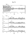
- FIG. 14 illustrates such a stimulation in an exemplary fashion.
- the modulation signals 51 , 52 , 53 and 54 have been obtained here from the band-pass filtered measurement signal 24 by means of linear processing steps, by means of which modulation signals the amplitude of frequencies f 1 to f 4 has been modulated.
- the control signal 14 has been generated by the superposition of the modulated sinusoidal oscillations, which control signal has been converted into the acoustic stimulation signal 15 by the sound generator 11 .
- FIGS. 15A and 15B are used to explain in an exemplary fashion how the modulation signals 51 to 54 can be obtained from the measurement signal 24 .
- Particular delay times ⁇ 1 , ⁇ 2 , ⁇ 3 and ⁇ 4 can be calculated for each of the modulation signals 51 to 54 with the aid of the delay time ⁇ , for example with the aid of the following equation:
- S 1 (t), S 2 (t), S 3 (t) and S 4 (t) represent the modulation signals 51 to 54 and Z(t) represents the measurement signal 24 .
- K is an amplification factor, which can be selected in a suitable fashion. Furthermore, all negative values (or all values above or below a particular threshold) of the modulation signals S 1 (t) to S 4 (t) can be set to zero.
- FIGS. 15A and 15B the modulation signals S 1 (t) and S 3 (t) have been displaced upward by a value of 0.5 and the modulation signals S 2 (t) and S 4 (t) have been displaced downward by a value of 0.5 for the purpose of a clearer illustration.
- all negative values (or all values above or below a certain threshold) of the modulation signals S 1 (t) to S 4 (t) can be set to zero.
- the generation of the modulation signals 51 to 54 shown in FIG. 14 corresponds to the generation of the modulation signals S 1 (t) to S 4 (t) shown in FIGS. 15A and 15B .
Abstract
Description
S(t)=K·
wherein X(t) can correspond to e.g. the
S(t)=K·[X(t)+iX(t−τ α)]2 ·[X(t−τ)−iX(t−τ−τ α)]. (3)
real[S(t)]=K·[X(t)2· X(t−τ)−X(t−τ α)·X(t−τ)+2X(t)·X(t−τ α)·X(t−τ−τ α)] (5)
S j(t)=K·Z(t−τ j). (7)
S 1(t)=K·Z(t−τ 1) (8)
S 2(t)=−K·Z(t−τ 1) (9)
S 3(t)=K·Z(t−τ 2) (10)
S 4(t)=−K·Z(t−τ 2). (11)
Claims (12)
S j(t)=K·Z(t−τ j) with j=1, . . . , N,
S j(t)=K·Z(t−τ j) with j=1, . . . , N,
Priority Applications (3)
| Application Number | Priority Date | Filing Date | Title |
|---|---|---|---|
| US13/796,422 US8825167B2 (en) | 2008-03-20 | 2013-03-12 | Device and method for auditory stimulation |
| US14/444,317 US9987191B2 (en) | 2008-03-20 | 2014-07-28 | Device and method for auditory stimulation |
| US15/996,819 US10973733B2 (en) | 2008-03-20 | 2018-06-04 | Device and method for auditory stimulation |
Applications Claiming Priority (6)
| Application Number | Priority Date | Filing Date | Title |
|---|---|---|---|
| DE102008015259.5 | 2008-03-20 | ||
| DE102008015259 | 2008-03-20 | ||
| DE102008015259A DE102008015259B4 (en) | 2008-03-20 | 2008-03-20 | Apparatus and method for auditory stimulation |
| PCT/DE2009/000399 WO2009115088A2 (en) | 2008-03-20 | 2009-03-20 | Device and method for auditory stimulation |
| US12/884,557 US8423144B2 (en) | 2008-03-20 | 2010-09-17 | Device and method for auditory stimulation |
| US13/796,422 US8825167B2 (en) | 2008-03-20 | 2013-03-12 | Device and method for auditory stimulation |
Related Parent Applications (3)
| Application Number | Title | Priority Date | Filing Date |
|---|---|---|---|
| PCT/DE2009/000399 Continuation WO2009115088A2 (en) | 2008-03-20 | 2009-03-20 | Device and method for auditory stimulation |
| US12884557 Continuation | 2009-03-20 | ||
| US12/884,557 Continuation US8423144B2 (en) | 2008-03-20 | 2010-09-17 | Device and method for auditory stimulation |
Related Child Applications (1)
| Application Number | Title | Priority Date | Filing Date |
|---|---|---|---|
| US14/444,317 Continuation US9987191B2 (en) | 2008-03-20 | 2014-07-28 | Device and method for auditory stimulation |
Publications (2)
| Publication Number | Publication Date |
|---|---|
| US20130190663A1 US20130190663A1 (en) | 2013-07-25 |
| US8825167B2 true US8825167B2 (en) | 2014-09-02 |
Family
ID=40791014
Family Applications (4)
| Application Number | Title | Priority Date | Filing Date |
|---|---|---|---|
| US12/884,557 Active US8423144B2 (en) | 2008-03-20 | 2010-09-17 | Device and method for auditory stimulation |
| US13/796,422 Active US8825167B2 (en) | 2008-03-20 | 2013-03-12 | Device and method for auditory stimulation |
| US14/444,317 Active 2030-04-22 US9987191B2 (en) | 2008-03-20 | 2014-07-28 | Device and method for auditory stimulation |
| US15/996,819 Active 2029-10-06 US10973733B2 (en) | 2008-03-20 | 2018-06-04 | Device and method for auditory stimulation |
Family Applications Before (1)
| Application Number | Title | Priority Date | Filing Date |
|---|---|---|---|
| US12/884,557 Active US8423144B2 (en) | 2008-03-20 | 2010-09-17 | Device and method for auditory stimulation |
Family Applications After (2)
| Application Number | Title | Priority Date | Filing Date |
|---|---|---|---|
| US14/444,317 Active 2030-04-22 US9987191B2 (en) | 2008-03-20 | 2014-07-28 | Device and method for auditory stimulation |
| US15/996,819 Active 2029-10-06 US10973733B2 (en) | 2008-03-20 | 2018-06-04 | Device and method for auditory stimulation |
Country Status (7)
| Country | Link |
|---|---|
| US (4) | US8423144B2 (en) |
| EP (2) | EP2826448B1 (en) |
| JP (1) | JP5280515B2 (en) |
| CN (2) | CN101977576B (en) |
| DE (1) | DE102008015259B4 (en) |
| ES (2) | ES2817832T3 (en) |
| WO (1) | WO2009115088A2 (en) |
Cited By (8)
| Publication number | Priority date | Publication date | Assignee | Title |
|---|---|---|---|---|
| US10413737B2 (en) | 2015-09-25 | 2019-09-17 | Boston Scientific Neuromodulation Corporation | Systems and methods for providing therapy using electrical stimulation to disrupt neuronal activity |
| US11027121B2 (en) | 2018-01-26 | 2021-06-08 | Regents Of The University Of Minnesota | Systems, methods and media for directional coordinated reset deep brain stimulation |
| US11273283B2 (en) | 2017-12-31 | 2022-03-15 | Neuroenhancement Lab, LLC | Method and apparatus for neuroenhancement to enhance emotional response |
| US11364361B2 (en) | 2018-04-20 | 2022-06-21 | Neuroenhancement Lab, LLC | System and method for inducing sleep by transplanting mental states |
| US11452839B2 (en) | 2018-09-14 | 2022-09-27 | Neuroenhancement Lab, LLC | System and method of improving sleep |
| US11717686B2 (en) | 2017-12-04 | 2023-08-08 | Neuroenhancement Lab, LLC | Method and apparatus for neuroenhancement to facilitate learning and performance |
| US11723579B2 (en) | 2017-09-19 | 2023-08-15 | Neuroenhancement Lab, LLC | Method and apparatus for neuroenhancement |
| US11786694B2 (en) | 2019-05-24 | 2023-10-17 | NeuroLight, Inc. | Device, method, and app for facilitating sleep |
Families Citing this family (36)
| Publication number | Priority date | Publication date | Assignee | Title |
|---|---|---|---|---|
| DE102008015259B4 (en) * | 2008-03-20 | 2010-07-22 | Anm Adaptive Neuromodulation Gmbh | Apparatus and method for auditory stimulation |
| DE102010000390A1 (en) | 2010-02-11 | 2011-08-11 | Forschungszentrum Jülich GmbH, 52428 | Apparatus and method for treating a patient with vibration, tactile and / or thermal implants |
| DE102010016404A1 (en) * | 2010-04-12 | 2012-12-27 | Forschungszentrum Jülich GmbH | Apparatus and method for conditioned desynchronizing non-invasive stimulation |
| DE102010016461B4 (en) | 2010-04-15 | 2013-03-21 | Forschungszentrum Jülich GmbH | Device for the treatment of diseases of the brain and / or spinal cord by means of neurofeedback |
| DK2533550T4 (en) | 2011-06-06 | 2021-07-05 | Oticon As | A hearing aid to reduce tinnitus volume |
| DE102012002436B4 (en) | 2012-02-08 | 2014-08-21 | Forschungszentrum Jülich GmbH | Apparatus for calibrating a non-invasive desynchronizing neurostimulation |
| EP2886149B1 (en) | 2012-08-16 | 2018-10-10 | Action Research Co., Ltd. | Vibration processing device |
| US20140052033A1 (en) * | 2012-08-20 | 2014-02-20 | BAUD Energetics, Corp | Device and method for pulsed acoustical stimulation of the brain |
| DE102012218057A1 (en) * | 2012-10-02 | 2014-04-03 | Forschungszentrum Jülich GmbH | DEVICE AND METHOD FOR INVESTIGATING A NARROW INTERACTION BETWEEN DIFFERENT BRAIN SIZES |
| JP2014116652A (en) * | 2012-12-06 | 2014-06-26 | Scalar Corp | Sensor device, sensor system, and program |
| US9764110B2 (en) * | 2013-03-22 | 2017-09-19 | Mind Rocket, Inc. | Binaural sleep inducing system |
| DE102013013278A1 (en) | 2013-08-08 | 2015-02-12 | Forschungszentrum Jülich GmbH | Apparatus and method for calibrating an acoustic desynchronizing neurostimulation |
| CN104055625A (en) * | 2014-06-11 | 2014-09-24 | 三峡大学 | Electroacoustic stimulator for treating tinnitus |
| DE102014115997B4 (en) * | 2014-11-03 | 2016-12-22 | Forschungszentrum Jülich GmbH | Device for effective non-invasive desynchronizing neurostimulation |
| DE102014115994B4 (en) * | 2014-11-03 | 2016-12-22 | Forschungszentrum Jülich GmbH | Device for effective invasive desynchronizing neurostimulation |
| FR3029117B1 (en) * | 2014-11-27 | 2022-05-06 | Dreem | SLOW BRAIN WAVE STIMULATION DEVICE AND METHOD |
| DE102014117427B4 (en) * | 2014-11-27 | 2016-12-15 | Forschungszentrum Jülich GmbH | Device for effective non-invasive neurostimulation by means of varying stimulus sequences |
| DE102015101371A1 (en) | 2015-01-30 | 2016-08-04 | Forschungszentrum Jülich GmbH | Apparatus and method for non-invasive neurostimulation using multi-channel bursts |
| DE102015101823A1 (en) | 2015-02-09 | 2016-08-11 | Forschungszentrum Jülich GmbH | Apparatus and method for calibrating a non-invasive mechanical tactile and / or thermal neurostimulation |
| US9724521B2 (en) | 2015-04-09 | 2017-08-08 | Medtronic, Inc. | Frequency based therapy generation |
| FR3039773A1 (en) * | 2015-08-04 | 2017-02-10 | Dreem | METHODS AND SYSTEMS FOR ACOUSTIC STIMULATION OF CEREBRAL WAVES. |
| EP3383482B1 (en) | 2015-11-24 | 2023-01-04 | Massachusetts Institute of Technology | Systems for preventing, mitigating, and/or treating dementia |
| DE102016104913B4 (en) * | 2016-03-16 | 2018-04-26 | Forschungszentrum Jülich GmbH | Device for effective, invasive and amplitude-modulated neurostimulation |
| DE102016009874A1 (en) | 2016-08-12 | 2018-02-15 | Forschungszentrum Jülich GmbH | Apparatus and method for hearing threshold adapted acoustic stimulation |
| EP3509549A4 (en) | 2016-09-06 | 2020-04-01 | Neosensory, Inc. | Method and system for providing adjunct sensory information to a user |
| US10960225B2 (en) | 2017-10-10 | 2021-03-30 | Massachusetts Institute Of Technology | Systems and methods for preventing, mitigating, and/or treating dementia via visual stimulation that binds higher order brain regions, reduces neurodegeneration and neuroinflammation, and improves cognitive function |
| AU2018347870B2 (en) | 2017-10-10 | 2022-12-08 | Massachusetts Institute Of Technology | Systems and methods for preventing, mitigating, and/or treating dementia |
| IT201800004742A1 (en) * | 2018-04-20 | 2019-10-20 | Software application on an electronic device for the reduction of head pain | |
| CN109260591B (en) * | 2018-08-02 | 2022-08-19 | 深圳英智科技有限公司 | Transcranial stimulation method and device |
| DE102018131534A1 (en) * | 2018-12-10 | 2020-06-25 | Joachim Loskill | Treatment device and handle for the treatment of the human body |
| WO2020220140A1 (en) * | 2019-05-02 | 2020-11-05 | Lucid Inc. | Device, method, and medium for integrating auditory beat stimulation into music |
| TWI708592B (en) * | 2019-05-09 | 2020-11-01 | 原相科技股份有限公司 | Method for generating sound reducing tinnitus effect and tinnitus control instrument performing the same |
| WO2021142162A1 (en) | 2020-01-07 | 2021-07-15 | Neosensory, Inc. | Method and system for haptic stimulation |
| US20220022790A1 (en) * | 2020-07-22 | 2022-01-27 | Actibrain Bio, Inc. | Ai (artificial intelligence) based device for providing brain information |
| US11497675B2 (en) * | 2020-10-23 | 2022-11-15 | Neosensory, Inc. | Method and system for multimodal stimulation |
| US11862147B2 (en) | 2021-08-13 | 2024-01-02 | Neosensory, Inc. | Method and system for enhancing the intelligibility of information for a user |
Citations (10)
| Publication number | Priority date | Publication date | Assignee | Title |
|---|---|---|---|---|
| JPH10512767A (en) | 1994-11-21 | 1998-12-08 | ニュロウトレイン、エル、シー | Evaluation of individuals using decentralization feedback of electroencephalograph |
| DE10233960A1 (en) | 2002-07-29 | 2004-02-19 | Forschungszentrum Jülich GmbH | Diagnosis and treatment device for dealing with abnormal, physiologically and or pathologically induced, neuronal rhythmic activity within the brain, comprising control unit, stimulator and brain activity sensor |
| WO2004098690A1 (en) | 2003-05-06 | 2004-11-18 | Oticon A/S | Tinnitus treatment |
| US20050049452A1 (en) | 2003-08-29 | 2005-03-03 | Lawlis G. Frank | Method and apparatus for acoustical stimulation of the brain |
| US20050234290A1 (en) | 2004-03-31 | 2005-10-20 | Lg Electronics Inc. | Apparatus and method for generating pulsating noise in audio device |
| US20060020161A1 (en) | 2004-07-20 | 2006-01-26 | James Mageras | Method and device for auditory stimulation for therapeutic application |
| US20060206175A1 (en) | 2003-11-14 | 2006-09-14 | Treno Corporation | Vestibular rehabilitation unit |
| WO2006126956A2 (en) | 2005-05-25 | 2006-11-30 | Guy Madison | Perceptible signals giving an impression of continuous pace change |
| US7917221B2 (en) * | 2003-04-17 | 2011-03-29 | Forschungszentrum Julich Gmbh | Device for the desynchronization of neuronal brain activity |
| US8423144B2 (en) * | 2008-03-20 | 2013-04-16 | Forschungszentrum Juelich Gmbh | Device and method for auditory stimulation |
Family Cites Families (3)
| Publication number | Priority date | Publication date | Assignee | Title |
|---|---|---|---|---|
| JPS6319134A (en) * | 1986-07-11 | 1988-01-26 | 工業技術院長 | Method and apparatus for stimulating nerve or irritable tissue |
| US7613520B2 (en) * | 2004-10-21 | 2009-11-03 | Advanced Neuromodulation Systems, Inc. | Spinal cord stimulation to treat auditory dysfunction |
| CA2599959A1 (en) * | 2005-03-01 | 2006-09-08 | Functional Neuroscience Inc. | Method of treating depression, mood disorders and anxiety disorders using neuromodulation |
-
2008
- 2008-03-20 DE DE102008015259A patent/DE102008015259B4/en active Active
- 2008-04-18 EP EP14186204.5A patent/EP2826448B1/en active Active
- 2008-04-18 ES ES14186204T patent/ES2817832T3/en active Active
- 2008-04-18 EP EP08007638.3A patent/EP2103288B1/en active Active
- 2008-04-18 ES ES08007638.3T patent/ES2529238T3/en active Active
-
2009
- 2009-03-20 CN CN200980109830.5A patent/CN101977576B/en active Active
- 2009-03-20 WO PCT/DE2009/000399 patent/WO2009115088A2/en active Application Filing
- 2009-03-20 JP JP2011500043A patent/JP5280515B2/en active Active
- 2009-03-20 CN CN201410379599.4A patent/CN104546289B/en not_active Expired - Fee Related
-
2010
- 2010-09-17 US US12/884,557 patent/US8423144B2/en active Active
-
2013
- 2013-03-12 US US13/796,422 patent/US8825167B2/en active Active
-
2014
- 2014-07-28 US US14/444,317 patent/US9987191B2/en active Active
-
2018
- 2018-06-04 US US15/996,819 patent/US10973733B2/en active Active
Patent Citations (13)
| Publication number | Priority date | Publication date | Assignee | Title |
|---|---|---|---|---|
| JPH10512767A (en) | 1994-11-21 | 1998-12-08 | ニュロウトレイン、エル、シー | Evaluation of individuals using decentralization feedback of electroencephalograph |
| US20060047324A1 (en) | 2002-07-29 | 2006-03-02 | Peter Tass | Device for modulation of neuronal activity in the brain by means of sensory stimulation and detection of brain activity |
| DE10233960A1 (en) | 2002-07-29 | 2004-02-19 | Forschungszentrum Jülich GmbH | Diagnosis and treatment device for dealing with abnormal, physiologically and or pathologically induced, neuronal rhythmic activity within the brain, comprising control unit, stimulator and brain activity sensor |
| US7917221B2 (en) * | 2003-04-17 | 2011-03-29 | Forschungszentrum Julich Gmbh | Device for the desynchronization of neuronal brain activity |
| WO2004098690A1 (en) | 2003-05-06 | 2004-11-18 | Oticon A/S | Tinnitus treatment |
| US20050049452A1 (en) | 2003-08-29 | 2005-03-03 | Lawlis G. Frank | Method and apparatus for acoustical stimulation of the brain |
| US7166070B2 (en) | 2003-08-29 | 2007-01-23 | Lawlis G Frank | Method and apparatus for acoustical stimulation of the brain |
| US7354395B2 (en) | 2003-08-29 | 2008-04-08 | Lawlis G Frank | Methods and apparatus for acoustical stimulation of the brain |
| US20060206175A1 (en) | 2003-11-14 | 2006-09-14 | Treno Corporation | Vestibular rehabilitation unit |
| US20050234290A1 (en) | 2004-03-31 | 2005-10-20 | Lg Electronics Inc. | Apparatus and method for generating pulsating noise in audio device |
| US20060020161A1 (en) | 2004-07-20 | 2006-01-26 | James Mageras | Method and device for auditory stimulation for therapeutic application |
| WO2006126956A2 (en) | 2005-05-25 | 2006-11-30 | Guy Madison | Perceptible signals giving an impression of continuous pace change |
| US8423144B2 (en) * | 2008-03-20 | 2013-04-16 | Forschungszentrum Juelich Gmbh | Device and method for auditory stimulation |
Non-Patent Citations (8)
| Title |
|---|
| B. Ross et al.; "Stimulus Induced Desynchronization of Human Auditory 40-Hz Steady-State Responses"; Journal of Neurophysiology 94, Aug. 17, 2005, pp. 4082-4093. |
| Dave R.M. Langers et al.; "Representation of lateralization and tonotopy in primary versus secondary human auditory cortex"; NeuroImage 34 (2007), pp. 264-273. |
| Deniz Bilecen et al.; "Tonotopic organization of the human auditory cortex as detected by BOLD-FMRI"; Hearing Research 126 1998, pp. 19-27. |
| M.E. Brandt; "Visual and auditory evoked phase resetting of the alpha EEG"; International Journal of Psychophysiology 26 (1997), pp. 285-298. |
| P. Sauseng et al.; "Are Event-Related Potential Components Generated by Phase Resetting of Brain Oscillations? A Critical Discussion"; Neuroscience 146 (2007), pp. 1435-1444. |
| Peter Lakatos et al.; "The Leading Sense: Supramodal Control of Neurophysiological Context by Attention"; Neuron 64, Nov. 12, 2009, pp. 419-430. |
| Scott Makeig et al.; "Mining event-related brain dynamics"; TRENDS in Cognitive Sciences, vol. 8 No. 5 May 2004. |
| Werner Muehlnickel et al.; "Reorganization of auditory cortex in tinnitus"; Proc. Natl. Acad. Sci USA, vol. 95, Aug. 1998, pp. 10340-10343. |
Cited By (10)
| Publication number | Priority date | Publication date | Assignee | Title |
|---|---|---|---|---|
| US10413737B2 (en) | 2015-09-25 | 2019-09-17 | Boston Scientific Neuromodulation Corporation | Systems and methods for providing therapy using electrical stimulation to disrupt neuronal activity |
| US11723579B2 (en) | 2017-09-19 | 2023-08-15 | Neuroenhancement Lab, LLC | Method and apparatus for neuroenhancement |
| US11717686B2 (en) | 2017-12-04 | 2023-08-08 | Neuroenhancement Lab, LLC | Method and apparatus for neuroenhancement to facilitate learning and performance |
| US11273283B2 (en) | 2017-12-31 | 2022-03-15 | Neuroenhancement Lab, LLC | Method and apparatus for neuroenhancement to enhance emotional response |
| US11318277B2 (en) | 2017-12-31 | 2022-05-03 | Neuroenhancement Lab, LLC | Method and apparatus for neuroenhancement to enhance emotional response |
| US11478603B2 (en) | 2017-12-31 | 2022-10-25 | Neuroenhancement Lab, LLC | Method and apparatus for neuroenhancement to enhance emotional response |
| US11027121B2 (en) | 2018-01-26 | 2021-06-08 | Regents Of The University Of Minnesota | Systems, methods and media for directional coordinated reset deep brain stimulation |
| US11364361B2 (en) | 2018-04-20 | 2022-06-21 | Neuroenhancement Lab, LLC | System and method for inducing sleep by transplanting mental states |
| US11452839B2 (en) | 2018-09-14 | 2022-09-27 | Neuroenhancement Lab, LLC | System and method of improving sleep |
| US11786694B2 (en) | 2019-05-24 | 2023-10-17 | NeuroLight, Inc. | Device, method, and app for facilitating sleep |
Also Published As
| Publication number | Publication date |
|---|---|
| US20110009921A1 (en) | 2011-01-13 |
| JP2011514220A (en) | 2011-05-06 |
| US10973733B2 (en) | 2021-04-13 |
| EP2103288B1 (en) | 2014-11-05 |
| EP2826448B1 (en) | 2020-06-24 |
| EP2103288A2 (en) | 2009-09-23 |
| EP2103288A3 (en) | 2009-12-16 |
| US20130190663A1 (en) | 2013-07-25 |
| ES2817832T3 (en) | 2021-04-08 |
| US20180325770A1 (en) | 2018-11-15 |
| CN101977576B (en) | 2014-09-03 |
| WO2009115088A3 (en) | 2009-12-30 |
| WO2009115088A2 (en) | 2009-09-24 |
| US20140336547A1 (en) | 2014-11-13 |
| DE102008015259A1 (en) | 2009-09-24 |
| US8423144B2 (en) | 2013-04-16 |
| CN104546289B (en) | 2018-08-10 |
| DE102008015259B4 (en) | 2010-07-22 |
| US9987191B2 (en) | 2018-06-05 |
| CN104546289A (en) | 2015-04-29 |
| JP5280515B2 (en) | 2013-09-04 |
| EP2826448A1 (en) | 2015-01-21 |
| ES2529238T3 (en) | 2015-02-18 |
| CN101977576A (en) | 2011-02-16 |
Similar Documents
| Publication | Publication Date | Title |
|---|---|---|
| US10973733B2 (en) | Device and method for auditory stimulation | |
| US20220088382A1 (en) | Nerve stimulator for use with a mobile device | |
| CN108697890B (en) | System and method for treating various neurological diseases by synchronously activating nerves | |
| US20200230020A1 (en) | Method and apparatus for treating various neurological conditions | |
| US8463378B2 (en) | Device and method for conditioned desynchronizing stimulation | |
| US10350410B2 (en) | Device and method for effective non-invasive neurostimulation by means of varying stimulus sequences | |
| US10722678B2 (en) | Device and method for effective non-invasive two-stage neurostimulation | |
| JP2018526122A (en) | System, apparatus and method for neural stimulation with packet modulation | |
| US10722711B2 (en) | Device for non-invasive neuro-stimulation by means of multichannel bursts | |
| US10701498B2 (en) | Systems and methods for treating tinnitus and enhancing hearing | |
| US20150290460A1 (en) | Methods for Treating Mild Cognitive Impairment and Alzheimer's Disease | |
| JP2019517381A (en) | Electrical stimulation device for innervation of the ear canal | |
| CN113347953A (en) | Apparatus and method for improving biological health | |
| RU2786615C2 (en) | Device and method for improvement of health state of living beings |
Legal Events
| Date | Code | Title | Description |
|---|---|---|---|
| FEPP | Fee payment procedure |
Free format text: PAYOR NUMBER ASSIGNED (ORIGINAL EVENT CODE: ASPN); ENTITY STATUS OF PATENT OWNER: LARGE ENTITY |
|
| STCF | Information on status: patent grant |
Free format text: PATENTED CASE |
|
| AS | Assignment |
Owner name: FORSCHUNGSZENTRUM JUELICH GMBH, GERMANY Free format text: ASSIGNMENT OF ASSIGNORS INTEREST;ASSIGNOR:ANM ADAPTIVE NEUROMODULATION GMBH;REEL/FRAME:036943/0009 Effective date: 20151015 |
|
| AS | Assignment |
Owner name: FORSCHUNGSZENTRUM JUELICH GMBH, GERMANY Free format text: ASSIGNMENT OF ASSIGNORS INTEREST;ASSIGNOR:UNIVERSITAET ZU KOELN;REEL/FRAME:042615/0796 Effective date: 20170524 |
|
| FEPP | Fee payment procedure |
Free format text: SURCHARGE FOR LATE PAYMENT, LARGE ENTITY (ORIGINAL EVENT CODE: M1554) |
|
| MAFP | Maintenance fee payment |
Free format text: PAYMENT OF MAINTENANCE FEE, 4TH YEAR, LARGE ENTITY (ORIGINAL EVENT CODE: M1551) Year of fee payment: 4 |
|
| MAFP | Maintenance fee payment |
Free format text: PAYMENT OF MAINTENANCE FEE, 8TH YEAR, LARGE ENTITY (ORIGINAL EVENT CODE: M1552); ENTITY STATUS OF PATENT OWNER: LARGE ENTITY Year of fee payment: 8 |
|
| AS | Assignment |
Owner name: PROFESSOR DR. PETER TASS, GERMANY Free format text: ASSIGNMENT OF ASSIGNORS INTEREST;ASSIGNOR:FORSCHUNGSZENTRUM JUELICH GMBH;REEL/FRAME:060092/0920 Effective date: 20220505 |
|
| AS | Assignment |
Owner name: GRETAP AG, SWITZERLAND Free format text: ASSIGNMENT OF ASSIGNORS INTEREST;ASSIGNOR:PROFESSOR DR. PETER TASS;REEL/FRAME:061160/0281 Effective date: 20211118 |