US8820441B2 - Combination coring bit and drill bit using fixed cutter PDC cutters - Google Patents
Combination coring bit and drill bit using fixed cutter PDC cutters Download PDFInfo
- Publication number
- US8820441B2 US8820441B2 US12/288,888 US28888808A US8820441B2 US 8820441 B2 US8820441 B2 US 8820441B2 US 28888808 A US28888808 A US 28888808A US 8820441 B2 US8820441 B2 US 8820441B2
- Authority
- US
- United States
- Prior art keywords
- blades
- drill bit
- polycrystalline diamond
- diamond compact
- core
- Prior art date
- Legal status (The legal status is an assumption and is not a legal conclusion. Google has not performed a legal analysis and makes no representation as to the accuracy of the status listed.)
- Expired - Fee Related, expires
Links
- 238000005520 cutting process Methods 0.000 claims abstract description 15
- 239000012141 concentrate Substances 0.000 claims abstract description 6
- 229910003460 diamond Inorganic materials 0.000 claims abstract 23
- 239000010432 diamond Substances 0.000 claims abstract 23
- 238000005553 drilling Methods 0.000 claims description 31
- 239000011435 rock Substances 0.000 claims description 20
- 230000015572 biosynthetic process Effects 0.000 claims description 12
- 239000012530 fluid Substances 0.000 claims description 6
- 238000000034 method Methods 0.000 claims description 4
- 239000011159 matrix material Substances 0.000 claims description 3
- 238000005755 formation reaction Methods 0.000 description 11
- 238000005096 rolling process Methods 0.000 description 7
- 230000004048 modification Effects 0.000 description 4
- 238000012986 modification Methods 0.000 description 4
- 230000000694 effects Effects 0.000 description 3
- 229910000831 Steel Inorganic materials 0.000 description 2
- 239000000463 material Substances 0.000 description 2
- 230000008569 process Effects 0.000 description 2
- 230000003014 reinforcing effect Effects 0.000 description 2
- 239000010959 steel Substances 0.000 description 2
- 235000015076 Shorea robusta Nutrition 0.000 description 1
- 244000166071 Shorea robusta Species 0.000 description 1
- 230000009471 action Effects 0.000 description 1
- 230000008901 benefit Effects 0.000 description 1
- 230000008859 change Effects 0.000 description 1
- 238000010276 construction Methods 0.000 description 1
- 238000005516 engineering process Methods 0.000 description 1
- 230000007717 exclusion Effects 0.000 description 1
- 230000002045 lasting effect Effects 0.000 description 1
- 238000004519 manufacturing process Methods 0.000 description 1
- 238000003801 milling Methods 0.000 description 1
- 230000002093 peripheral effect Effects 0.000 description 1
- 239000011044 quartzite Substances 0.000 description 1
- UONOETXJSWQNOL-UHFFFAOYSA-N tungsten carbide Chemical compound [W+]#[C-] UONOETXJSWQNOL-UHFFFAOYSA-N 0.000 description 1
- 230000003313 weakening effect Effects 0.000 description 1
Images


Classifications
-
- E—FIXED CONSTRUCTIONS
- E21—EARTH OR ROCK DRILLING; MINING
- E21B—EARTH OR ROCK DRILLING; OBTAINING OIL, GAS, WATER, SOLUBLE OR MELTABLE MATERIALS OR A SLURRY OF MINERALS FROM WELLS
- E21B10/00—Drill bits
- E21B10/46—Drill bits characterised by wear resisting parts, e.g. diamond inserts
- E21B10/48—Drill bits characterised by wear resisting parts, e.g. diamond inserts the bit being of core type
-
- E—FIXED CONSTRUCTIONS
- E21—EARTH OR ROCK DRILLING; MINING
- E21B—EARTH OR ROCK DRILLING; OBTAINING OIL, GAS, WATER, SOLUBLE OR MELTABLE MATERIALS OR A SLURRY OF MINERALS FROM WELLS
- E21B10/00—Drill bits
- E21B10/02—Core bits
- E21B10/04—Core bits with core destroying means
-
- E—FIXED CONSTRUCTIONS
- E21—EARTH OR ROCK DRILLING; MINING
- E21B—EARTH OR ROCK DRILLING; OBTAINING OIL, GAS, WATER, SOLUBLE OR MELTABLE MATERIALS OR A SLURRY OF MINERALS FROM WELLS
- E21B10/00—Drill bits
- E21B10/46—Drill bits characterised by wear resisting parts, e.g. diamond inserts
- E21B10/54—Drill bits characterised by wear resisting parts, e.g. diamond inserts the bit being of the rotary drag type, e.g. fork-type bits
Definitions
- This invention relates generally to the use of coring bit technology in combination with a drill bit used for drilling an earth borehole, and more particularly, to a combination coring bit and drill bit using fixed cutter PDC cutters for both functions.
- a rock bit In the field of exploration and production of oil and gas, one type of drill bit, sometimes referred to as a rock bit, is used for drilling earth boreholes and is commonly known as a rotary cone drill bit.
- the typical rotary cone drill bit employs a multiplicity of rolling cone cutters rotatably mounted to extend downwardly and inwardly with respect to the central access of the drill bit.
- the rolling cone cutters may have milled teeth or cutter inserts disposed on each cutter in predefined patterns.
- the predefined teeth or insert pattern of each rolling cone cutter are typically different from one another so that the teeth or inserts of the cone cutters mesh as the cone cutters are rotated. In constructed in this manner, the teeth are inserts located on the conical sides of the cutter do not create grooves in the borehole. Further, the meshing rotating teeth or inserts on the conical sides is capable of contacting and cutting the entire bottom of the borehole.
- the typical rotary cone drill bit has been the tool of choice for drilling earth boreholes, several undesirable phenomenon affects the efficiency and performance of the bit.
- the teeth or inserts located at or near the conical tips of the rolling cone cutters mesh and cut the center of the borehole. Because of the rotary cone drill bit configuration, the rotation of the conical tips of the rolling cone cutters travels the least amount of distance. Indeed, certain teeth or inserts may remain substantially stationary but for the rotational movement. Because the amount of cutting is directly related to the movement of the teeth or inserts, it is a poor translation of rotation energy to the cutting structures which generate little rock removal. Therefore the center of the well bore present a special challenge to the progress of the drilling.
- one measure of the rotary cone drill bits performance is its ability to maintain a consistent borehole diameter. This ability to hold gauge is important to enable drill strings to be easily removed from and inserted into the borehole. Gauge holding is particularly important for directional drilling applications.
- a further disadvantage associated with typical rotary cone drill bits is the tendency for the conical cutters to cut under-gauge. As the drill bit advances, the rock formation tends to pinch or force the rolling cone cutters and the support arms inwardly. The results in a borehole that is under-gauge.
- U.S. Pat. No. 5,695,019 introduced the concept of using a coring device to create a central core in the center of the borehole which prevents the rotary cones from being pinched in the drilling process.
- the core produced in U.S. Pat. No. 5,695,019 had a really small diameter, some 0.25 inches to 1.0 inches, and would tend to fall down on their own, a concept having no particular relevance to the present invention.
- the present invention provides a bit design which is based on utilizing the concept of coring as part of the drilling process.
- roller cone rock bits have been used to drill the very hard formations, essentially to the exclusion of using PDC cutters in such formations.
- the PDC cutters can be used to drill in very hard rock in accordance with the present invention.
- the outer diameter of the well bore must be drilled first.
- the outermost portions of the bit profile are designed similar in profile to a standard PDC core head, with both inner and outer vertical gauge sections and inner and outer gauge reliefs.
- the inner gauge relief allows for the core stump to stand free of support by the leading cutting structure.
- Blades are used to position the cutters with a core-head like terminus, as illustrated hereinafter, or thicker lug-like protuberances as are also illustrated hereinafter.
- the common coring profile is exhibited where the outer portion of the borehole is drilled first.
- Embodiments of the drill bits shown in FIGS. 1D , 2 A, and 2 B depict the inner gauge relief 31 as a channel (e.g. a groove, recess, etc.).
- An additional feature of the present invention involves the use of a core-head like profile as the nose of the bit, thus effectively locking the cutting structure into the bottom hole pattern, disallowing strong lateral movement and minimizing the effects of drill string vibrations.
- the core stump provides a great degree of lateral stability, disallowing large lateral movement.
- a self-stabilizing cutting structure on the core/gauge terminus of the blades a very stable bit is created. This is effectively the “tool rest” for the PDC cutters, and thus they are in more of a “formation milling” mode of operation that an engrossed, less stabilized drilling mode traditionally associated with typical PDC cutter designs. This results in a longer lasting PDC cutter and reduced PDC cutter chipping.
- the bit in accordance with the present invention is very difficult to move laterally, which makes it have very stable directionally.
- For the bit to move laterally one has to essentially break the core stump off. Thus it is very likely that this bit will maintain any angle built into the well very effectively. It also tends to resist following a fault or similar change in dispositional planes.
- a frustum can be formed in the center of the bit, and thus be made to increase the residual stress in the bottom of the hole.
- These optional design modifications may include a series of steps, waves, ridges or any other geometric shape inherent in the bottom hole pattern which concentrates stress and weakens the rock.
- Additional modifications can be made or created on a smaller scale by cutter placement.
- cutters By placing cutters in a highly redundant fashion (identical Y position with respect to midline) and closely adjacent to each other a very heavily scalloped bottom hole profile is created.
- the scalloped bottom hole pattern induces additional stresses in the native rock, further weakening the rock.
- Saw tooth and other obvious patterns can be built into the design in similar fashion.
- cutter shapes can be employed to develop stresses, such as a pointed cutter adjacent to a round cutter.
- An elliptical cutter next to a round cutter, or cutters set at varying heights which provide obvious alternatives to develop stresses in the rock.
- Even different size round cutters placed adjacently will develop stress risers which weaken formation strength and promote rupture of the rock.
- the combination of the gross profile of the design and the optional cutting structure patterns, or cutter geometry modifications will result in a drill bit that significantly weakens the end-situ rock strength and will promote formation rupture at lower energy levels, resulting in a more rapid removal of formation when drilling very hard rock.
- FIG. 1A is an elevated, isometric, pictorial view of a six bladed drill bit according to the invention
- FIG. 1B is a side view of the drill bit according to FIG. 1A ;
- FIG. 1C is a bottom end view of the drill bit according to FIG. 1A ;
- FIG. 1D is an elevated view, partly in cross-section, of the drill bit according to FIG. 1A ;
- FIG. 2A is an elevated, isometric, pictorial view of a three leg drill bit according to the invention
- FIG. 2B is a side view of the drill bit according to FIG. 2A ;
- FIG. 2C is a bottom end view of the drill bit according to FIG. 2A ;
- FIG. 3A is an elevated, isometric, pictorial view of a six bladed drill bit having a webbing or ring support between the blades according to the invention
- FIG. 3B is a side view of the drill bit according to FIG. 3A ;
- FIG. 3C is a bottom view of the drill bit according to FIG. 3A ;
- FIG. 3D is an elevated, pictorial view, partly in cross-section, of the drill bit according to FIG. 3A ;
- FIG. 4 is an elevated schematic view of the stress concentrations around the lower periphery of the core stump produced by the drill bit according to the invention.
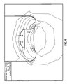
- FIG. 5 is an elevated, schematic view of the stress concentrations around the lower periphery of the core stump produced by the drill bit having a frustum at the midline of the drill bit according to the invention.
- FIG. 6 is an elevated, schematic view of the stress concentrations resulting in the rock formations from using a conventional PDC drill bit known in the prior art.
- FIGS. 1A , 1 B, 1 C and 1 D illustrate a drill bit 10 having a threaded pin end 12 which can be threaded into the box end of a joint of drill pipe (not illustrated).
- Each of the blades 14 , 16 , 18 , 20 , 22 and 24 has its own wear gauge pad 26 .
- Each of the blades is further shown comprising a side surface 32 a and 32 b , which defines an open space or a channel 33 therebetween.
- Each of the blades has a row of PDC cutters 28 . It should appreciated that for each of the blades, the row of PDC cutters 28 starts off from the wear pad 26 , as best illustrated in FIG. 1D .
- the rotation of the bit causes the u-shape portion of the row of PDC cutters to drill around what ends up being the core which is uncut until later when the PDC cutters in the relief portion 30 cause the core stump to disintegrate and be drilled out.
- the PDC cutters in the relief section is identified by the numeral 29 .
- the relief section cutters 29 are also illustrated in FIG. 1C .
- the core stump is first formed by the action of the PDC cutters 28 and after the core is formed, the PDC cutters 29 will cause stress forces to be formed around the lower periphery of the stump which will then enable the cutters to 29 to drill more easily through the stump.
- the core at its top end will always have a diameter greater than 1.0 inches, and will typically have diameters at the top end of the core in the range of 2.0 to 7.0 inches.
- the drill bit 10 according the present invention illustrated in FIG. 1A has a plurality of nozzles, a first set of three larger nozzles 40 , 47 and 49 and three smaller nozzles 46 , 48 and 50 which cause the drilling fluid to exit around the PDC cutters 29 in the relief surface 30 .
- FIGS. 2A , 2 B and 2 C there is illustrated a lug designed PDC drill bit having three lugs 50 , 52 and 54 . Each of the blades is further shown comprising a side surface 32 a and 32 b , which defines an open space or a channel 33 therebetween.
- the bit 70 has its own nozzles 56 , 58 and 60 which enable drilling mud to exit close to the PDC cutters, respectively, in the relief areas 62 , 64 and 66 .
- the PDC drill bits 70 , the lugs 50 , 52 and 54 each has a wear gauge pad 80 which assists in keeping the drill bit in gauge in drilling the earth borehole.
- the PDC drill bits 70 also has a threaded pin end 82 for threadedly connecting into the box end of a joint drill pipe (not illustrated).
- FIGS. 3A , 3 B, 3 C and 3 D function much the same as the drill bit illustrated in FIGS. 1A , 1 B, 1 C and 1 D, other than for the optional webbing or ring 100 which provides mechanical supports for the six (6) blades.
- FIG. 6 there is illustrated stress concentrations from the use of a prior art PDC drill bit in which the stress concentrations are all towards the lower end of the bore hole but are not concentrated as described herein in accordance with the invention.
- FIG. 4 there is illustrated a schematic view of the stress forces according to the present invention wherein the top of the core is a dome shape resulting from the curvatures of the cutters 29 illustrated in FIG. 1D resulting from the cutters 29 being forced against the top of the core, thus causing the stress concentration around the upper periphery of the core stump. This causes any forces created by the cutters 29 to cause the stump to rupture and be easily drilled out.
- FIG. 5 illustrates an alternative embodiment of the invention where, in aiding the drilling the of core stump, a frustum is used at the top of the dome which further concentrates the stresses around the periphery of the upper end of the core stump, thus enabling the rupture of the core stump and the faster drilling out the core stump as contemplated by this invention.
Landscapes
- Engineering & Computer Science (AREA)
- Life Sciences & Earth Sciences (AREA)
- Geology (AREA)
- Mining & Mineral Resources (AREA)
- Mechanical Engineering (AREA)
- Physics & Mathematics (AREA)
- Environmental & Geological Engineering (AREA)
- Fluid Mechanics (AREA)
- General Life Sciences & Earth Sciences (AREA)
- Geochemistry & Mineralogy (AREA)
- Earth Drilling (AREA)
- Processing Of Stones Or Stones Resemblance Materials (AREA)
Abstract
Description
Claims (17)
Priority Applications (2)
| Application Number | Priority Date | Filing Date | Title |
|---|---|---|---|
| US12/288,888 US8820441B2 (en) | 2008-10-24 | 2008-10-24 | Combination coring bit and drill bit using fixed cutter PDC cutters |
| PCT/US2009/005758 WO2010047810A1 (en) | 2008-10-24 | 2009-10-22 | Combination coring bit and drill bit using fixed cutter pdc cutters |
Applications Claiming Priority (1)
| Application Number | Priority Date | Filing Date | Title |
|---|---|---|---|
| US12/288,888 US8820441B2 (en) | 2008-10-24 | 2008-10-24 | Combination coring bit and drill bit using fixed cutter PDC cutters |
Publications (2)
| Publication Number | Publication Date |
|---|---|
| US20100101870A1 US20100101870A1 (en) | 2010-04-29 |
| US8820441B2 true US8820441B2 (en) | 2014-09-02 |
Family
ID=42116420
Family Applications (1)
| Application Number | Title | Priority Date | Filing Date |
|---|---|---|---|
| US12/288,888 Expired - Fee Related US8820441B2 (en) | 2008-10-24 | 2008-10-24 | Combination coring bit and drill bit using fixed cutter PDC cutters |
Country Status (2)
| Country | Link |
|---|---|
| US (1) | US8820441B2 (en) |
| WO (1) | WO2010047810A1 (en) |
Cited By (3)
| Publication number | Priority date | Publication date | Assignee | Title |
|---|---|---|---|---|
| EP3249150A1 (en) | 2016-05-23 | 2017-11-29 | VAREL EUROPE (Société par Actions Simplifiée) | Fixed cutter drill bit having core receptacle with concave core cutter |
| US11060357B2 (en) | 2017-09-29 | 2021-07-13 | Baker Hughes Holdings Llc | Earth-boring tools having a selectively tailored gauge region for reduced bit walk and method of drilling with same |
| US11255127B2 (en) * | 2019-11-19 | 2022-02-22 | China University Of Petroleum (East China) | Drill bit with joint function of induced unloading and abrasive jet and drilling method thereof |
Families Citing this family (9)
| Publication number | Priority date | Publication date | Assignee | Title |
|---|---|---|---|---|
| CA2827116C (en) | 2011-02-10 | 2016-06-14 | Smith International, Inc. | Cutting structures for fixed cutter drill bit and other downhole cutting tools |
| CA2839696C (en) * | 2011-06-22 | 2019-10-29 | Smith International, Inc. | Fixed cutter drill bit with core fragmentation feature |
| US10125550B2 (en) * | 2013-09-11 | 2018-11-13 | Smith International, Inc. | Orientation of cutting element at first radial position to cut core |
| US10301881B2 (en) * | 2013-09-11 | 2019-05-28 | Smith International, Inc. | Fixed cutter drill bit with multiple cutting elements at first radial position to cut core |
| US9725959B2 (en) * | 2013-09-13 | 2017-08-08 | Drilformance Technologies, Llc | Cutter profile for a fixed cutter drill bit |
| US9702197B2 (en) * | 2014-04-29 | 2017-07-11 | Wwt North America Holdings, Inc. | Reamer shoe attachment for flexible casing shoe |
| CN107642335A (en) * | 2017-10-27 | 2018-01-30 | 中国水利水电第十工程局有限公司 | Can in interbedding of soft and hard rocks rock fast drilling PDC drill bit |
| CN110080686B (en) * | 2019-05-14 | 2024-07-23 | 河南四方达超硬材料股份有限公司 | Polycrystalline diamond down-the-hole drill bit |
| CN116641657B (en) * | 2023-07-25 | 2023-09-29 | 西南石油大学 | Anti-balling PDC drill bit |
Citations (13)
| Publication number | Priority date | Publication date | Assignee | Title |
|---|---|---|---|---|
| US2731236A (en) * | 1953-10-05 | 1956-01-17 | Bruce Floyd | Diamond drill bit |
| US3100544A (en) | 1960-05-31 | 1963-08-13 | Jersey Prod Res Co | Drilling device |
| US3599736A (en) * | 1970-05-18 | 1971-08-17 | American Coldset Corp | Rotary drill bit |
| US3640355A (en) * | 1970-06-04 | 1972-02-08 | Maurice P Lebourg | Drill bit |
| US4207954A (en) * | 1977-03-31 | 1980-06-17 | Compagnie Francaise Des Petroles | Core bit having axial conical core breaker |
| US4527644A (en) * | 1983-03-25 | 1985-07-09 | Allam Farouk M | Drilling bit |
| US4558753A (en) * | 1983-02-22 | 1985-12-17 | Nl Industries, Inc. | Drag bit and cutters |
| US5467836A (en) | 1992-01-31 | 1995-11-21 | Baker Hughes Incorporated | Fixed cutter bit with shear cutting gage |
| US5655614A (en) * | 1994-12-20 | 1997-08-12 | Smith International, Inc. | Self-centering polycrystalline diamond cutting rock bit |
| US5695019A (en) * | 1995-08-23 | 1997-12-09 | Dresser Industries, Inc. | Rotary cone drill bit with truncated rolling cone cutters and dome area cutter inserts |
| US20070215389A1 (en) * | 2006-03-17 | 2007-09-20 | Halliburton Energy Services, Inc. | Matrix Drill Bits With Back Raked Cutting Elements |
| US7278499B2 (en) * | 2005-01-26 | 2007-10-09 | Baker Hughes Incorporated | Rotary drag bit including a central region having a plurality of cutting structures |
| US7954571B2 (en) * | 2007-10-02 | 2011-06-07 | Baker Hughes Incorporated | Cutting structures for casing component drillout and earth-boring drill bits including same |
-
2008
- 2008-10-24 US US12/288,888 patent/US8820441B2/en not_active Expired - Fee Related
-
2009
- 2009-10-22 WO PCT/US2009/005758 patent/WO2010047810A1/en active Application Filing
Patent Citations (13)
| Publication number | Priority date | Publication date | Assignee | Title |
|---|---|---|---|---|
| US2731236A (en) * | 1953-10-05 | 1956-01-17 | Bruce Floyd | Diamond drill bit |
| US3100544A (en) | 1960-05-31 | 1963-08-13 | Jersey Prod Res Co | Drilling device |
| US3599736A (en) * | 1970-05-18 | 1971-08-17 | American Coldset Corp | Rotary drill bit |
| US3640355A (en) * | 1970-06-04 | 1972-02-08 | Maurice P Lebourg | Drill bit |
| US4207954A (en) * | 1977-03-31 | 1980-06-17 | Compagnie Francaise Des Petroles | Core bit having axial conical core breaker |
| US4558753A (en) * | 1983-02-22 | 1985-12-17 | Nl Industries, Inc. | Drag bit and cutters |
| US4527644A (en) * | 1983-03-25 | 1985-07-09 | Allam Farouk M | Drilling bit |
| US5467836A (en) | 1992-01-31 | 1995-11-21 | Baker Hughes Incorporated | Fixed cutter bit with shear cutting gage |
| US5655614A (en) * | 1994-12-20 | 1997-08-12 | Smith International, Inc. | Self-centering polycrystalline diamond cutting rock bit |
| US5695019A (en) * | 1995-08-23 | 1997-12-09 | Dresser Industries, Inc. | Rotary cone drill bit with truncated rolling cone cutters and dome area cutter inserts |
| US7278499B2 (en) * | 2005-01-26 | 2007-10-09 | Baker Hughes Incorporated | Rotary drag bit including a central region having a plurality of cutting structures |
| US20070215389A1 (en) * | 2006-03-17 | 2007-09-20 | Halliburton Energy Services, Inc. | Matrix Drill Bits With Back Raked Cutting Elements |
| US7954571B2 (en) * | 2007-10-02 | 2011-06-07 | Baker Hughes Incorporated | Cutting structures for casing component drillout and earth-boring drill bits including same |
Cited By (6)
| Publication number | Priority date | Publication date | Assignee | Title |
|---|---|---|---|---|
| EP3249150A1 (en) | 2016-05-23 | 2017-11-29 | VAREL EUROPE (Société par Actions Simplifiée) | Fixed cutter drill bit having core receptacle with concave core cutter |
| US10329843B2 (en) | 2016-05-23 | 2019-06-25 | Varel Europe S.A.S. | Fixed cutter drill bit having core receptacle with concave core cutter |
| US11060357B2 (en) | 2017-09-29 | 2021-07-13 | Baker Hughes Holdings Llc | Earth-boring tools having a selectively tailored gauge region for reduced bit walk and method of drilling with same |
| US11332980B2 (en) | 2017-09-29 | 2022-05-17 | Baker Hughes Holdings Llc | Earth-boring tools having a gauge insert configured for reduced bit walk and method of drilling with same |
| US11421484B2 (en) | 2017-09-29 | 2022-08-23 | Baker Hughes Holdings Llc | Earth-boring tools having a gauge region configured for reduced bit walk and method of drilling with same |
| US11255127B2 (en) * | 2019-11-19 | 2022-02-22 | China University Of Petroleum (East China) | Drill bit with joint function of induced unloading and abrasive jet and drilling method thereof |
Also Published As
| Publication number | Publication date |
|---|---|
| WO2010047810A1 (en) | 2010-04-29 |
| US20100101870A1 (en) | 2010-04-29 |
Similar Documents
| Publication | Publication Date | Title |
|---|---|---|
| US8820441B2 (en) | Combination coring bit and drill bit using fixed cutter PDC cutters | |
| US10745973B2 (en) | Securing mechanism for a drilling element on a downhole drilling tool | |
| US6176333B1 (en) | Diamond cap cutting elements with flats | |
| US5758733A (en) | Earth-boring bit with super-hard cutting elements | |
| US8210288B2 (en) | Rotary drill bits with protected cutting elements and methods | |
| EP2118431B1 (en) | Rotary drag bit | |
| US20090159341A1 (en) | Reamer with balanced cutting structures for use in a wellbore | |
| US6904983B2 (en) | Low-contact area cutting element | |
| CN105269047A (en) | Cutting insert for initiating a cutout | |
| US10597946B2 (en) | Drill bits with internally tapered blade and trimming cutting elements | |
| EA032667B1 (en) | Downhole rock cutting tool | |
| US10570665B2 (en) | Drill bit | |
| US20190010763A1 (en) | Angled chisel insert | |
| CN105683484A (en) | Orientation of cutting element at first radial position to cut core | |
| US20060011388A1 (en) | Drill bit and cutter element having multiple extensions | |
| EP3363988B1 (en) | Impregnated drill bit including a planar blade profile along drill bit face | |
| US9284786B2 (en) | Drill bits having depth of cut control features and methods of making and using the same | |
| US20060219442A1 (en) | Earth-boring bit with shear cutting elements | |
| US11655681B2 (en) | Inner cutter for drilling | |
| US10012029B2 (en) | Rolling cones with gage cutting elements, earth-boring tools carrying rolling cones with gage cutting elements and related methods | |
| US20140262536A1 (en) | Downhole cutting tools having hybrid cutting structures | |
| US9284785B2 (en) | Drill bits having depth of cut control features and methods of making and using the same | |
| WO2014028152A1 (en) | Downhole cutting tools having hybrid cutting structures | |
| US2209619A (en) | Cable tool drill | |
| US11208847B2 (en) | Stepped downhole tools and methods of use |
Legal Events
| Date | Code | Title | Description |
|---|---|---|---|
| AS | Assignment |
Owner name: ENCORE BITS, LLC,TEXAS Free format text: ASSIGNMENT OF ASSIGNORS INTEREST;ASSIGNOR:SHAMBURGER, JAMES;REEL/FRAME:021856/0190 Effective date: 20081111 Owner name: ENCORE BITS, LLC, TEXAS Free format text: ASSIGNMENT OF ASSIGNORS INTEREST;ASSIGNOR:SHAMBURGER, JAMES;REEL/FRAME:021856/0190 Effective date: 20081111 |
|
| AS | Assignment |
Owner name: OMNI LP LTD.,TEXAS Free format text: ASSIGNMENT OF ASSIGNORS INTEREST;ASSIGNOR:ENCORE BITS, LLC;REEL/FRAME:024051/0331 Effective date: 20100304 Owner name: OMNI LP LTD., TEXAS Free format text: ASSIGNMENT OF ASSIGNORS INTEREST;ASSIGNOR:ENCORE BITS, LLC;REEL/FRAME:024051/0331 Effective date: 20100304 |
|
| AS | Assignment |
Owner name: OMNI IP LTD.,VIRGIN ISLANDS, BRITISH Free format text: ADDRESS CHANGE AND CORRECTION FOR ASSIGNMENT RECORDED AT REEL/FRAME 024051/0331. THE NEW ADDRESS IS LISTED ABOVE AND THE CORRECT SPELLING OF THE ASSIGNEE NAME IS OMNI IP LTD;ASSIGNOR:OMNI IP LTD.;REEL/FRAME:024534/0336 Effective date: 20100304 Owner name: OMNI IP LTD., VIRGIN ISLANDS, BRITISH Free format text: ADDRESS CHANGE AND CORRECTION FOR ASSIGNMENT RECORDED AT REEL/FRAME 024051/0331. THE NEW ADDRESS IS LISTED ABOVE AND THE CORRECT SPELLING OF THE ASSIGNEE NAME IS OMNI IP LTD;ASSIGNOR:OMNI IP LTD.;REEL/FRAME:024534/0336 Effective date: 20100304 |
|
| FEPP | Fee payment procedure |
Free format text: PAYOR NUMBER ASSIGNED (ORIGINAL EVENT CODE: ASPN); ENTITY STATUS OF PATENT OWNER: SMALL ENTITY |
|
| STCF | Information on status: patent grant |
Free format text: PATENTED CASE |
|
| AS | Assignment |
Owner name: TERCEL IP LTD., VIRGIN ISLANDS, BRITISH Free format text: CHANGE OF NAME;ASSIGNOR:OMNI IP LTD.;REEL/FRAME:033577/0438 Effective date: 20110627 |
|
| AS | Assignment |
Owner name: SILICON VALLEY BANK, CALIFORNIA Free format text: SECURITY INTEREST;ASSIGNOR:TERCEL IP LTD.;REEL/FRAME:036216/0095 Effective date: 20150728 |
|
| FEPP | Fee payment procedure |
Free format text: MAINTENANCE FEE REMINDER MAILED (ORIGINAL EVENT CODE: REM.) |
|
| FEPP | Fee payment procedure |
Free format text: SURCHARGE FOR LATE PAYMENT, SMALL ENTITY (ORIGINAL EVENT CODE: M2554) |
|
| MAFP | Maintenance fee payment |
Free format text: PAYMENT OF MAINTENANCE FEE, 4TH YR, SMALL ENTITY (ORIGINAL EVENT CODE: M2551) Year of fee payment: 4 |
|
| AS | Assignment |
Owner name: TERCEL IP LTD., TEXAS Free format text: RELEASE BY SECURED PARTY;ASSIGNOR:SILICON VALLEY BANK;REEL/FRAME:047900/0534 Effective date: 20181217 |
|
| AS | Assignment |
Owner name: DIAMANT DRILLING SERVICES SA, BELGIUM Free format text: ASSIGNMENT OF ASSIGNORS INTEREST;ASSIGNOR:TERCEL IP LTD.;REEL/FRAME:048076/0240 Effective date: 20181107 |
|
| FEPP | Fee payment procedure |
Free format text: MAINTENANCE FEE REMINDER MAILED (ORIGINAL EVENT CODE: REM.); ENTITY STATUS OF PATENT OWNER: SMALL ENTITY |
|
| LAPS | Lapse for failure to pay maintenance fees |
Free format text: PATENT EXPIRED FOR FAILURE TO PAY MAINTENANCE FEES (ORIGINAL EVENT CODE: EXP.); ENTITY STATUS OF PATENT OWNER: SMALL ENTITY |
|
| STCH | Information on status: patent discontinuation |
Free format text: PATENT EXPIRED DUE TO NONPAYMENT OF MAINTENANCE FEES UNDER 37 CFR 1.362 |
|
| FP | Lapsed due to failure to pay maintenance fee |
Effective date: 20220902 |