US8820256B2 - Frictional resistance reducing device of ship - Google Patents
Frictional resistance reducing device of ship Download PDFInfo
- Publication number
- US8820256B2 US8820256B2 US13/376,221 US201013376221A US8820256B2 US 8820256 B2 US8820256 B2 US 8820256B2 US 201013376221 A US201013376221 A US 201013376221A US 8820256 B2 US8820256 B2 US 8820256B2
- Authority
- US
- United States
- Prior art keywords
- gas room
- scattering member
- opening
- longitudinal frame
- frictional resistance
- Prior art date
- Legal status (The legal status is an assumption and is not a legal conclusion. Google has not performed a legal analysis and makes no representation as to the accuracy of the status listed.)
- Expired - Fee Related, expires
Links
Images


Classifications
-
- B—PERFORMING OPERATIONS; TRANSPORTING
- B63—SHIPS OR OTHER WATERBORNE VESSELS; RELATED EQUIPMENT
- B63B—SHIPS OR OTHER WATERBORNE VESSELS; EQUIPMENT FOR SHIPPING
- B63B1/00—Hydrodynamic or hydrostatic features of hulls or of hydrofoils
- B63B1/32—Other means for varying the inherent hydrodynamic characteristics of hulls
- B63B1/34—Other means for varying the inherent hydrodynamic characteristics of hulls by reducing surface friction
- B63B1/38—Other means for varying the inherent hydrodynamic characteristics of hulls by reducing surface friction using air bubbles or air layers gas filled volumes
- B63B2001/387—Other means for varying the inherent hydrodynamic characteristics of hulls by reducing surface friction using air bubbles or air layers gas filled volumes using means for producing a film of air or air bubbles over at least a significant portion of the hull surface
-
- Y—GENERAL TAGGING OF NEW TECHNOLOGICAL DEVELOPMENTS; GENERAL TAGGING OF CROSS-SECTIONAL TECHNOLOGIES SPANNING OVER SEVERAL SECTIONS OF THE IPC; TECHNICAL SUBJECTS COVERED BY FORMER USPC CROSS-REFERENCE ART COLLECTIONS [XRACs] AND DIGESTS
- Y02—TECHNOLOGIES OR APPLICATIONS FOR MITIGATION OR ADAPTATION AGAINST CLIMATE CHANGE
- Y02T—CLIMATE CHANGE MITIGATION TECHNOLOGIES RELATED TO TRANSPORTATION
- Y02T70/00—Maritime or waterways transport
- Y02T70/10—Measures concerning design or construction of watercraft hulls
-
- Y02T70/122—
Definitions
- the present invention is related to a frictional resistance reducing device which reduces frictional resistance of a hull through air blowing.
- a technique which reduces frictional resistance of a hull by covering the bottom surface of a ship with an air bubble flow at the time of navigation.
- a gas room 2 is provided on the bow side in a bottom section 1 of a ship.
- the gas room 2 is formed in the width direction.
- the gas room 2 is divided into three gas rooms 2 a in the width direction of the ship bottom section 1 by partitions 2 b . Parts of the outer plate of the ship bottom corresponding to the gas rooms 2 a are cut to form bottom openings 1 a with no bottom plate.
- Each gas room 2 a is connected with a compressor 4 through the gas supply pipe 3 .
- a baffle plate 6 is provided apart below from a connection opening of the gas supply pipe 3 in the top wall to receive a gaseous flow.
- a pair of gas holding boards 5 is provided from a bow section toward a stern section along the both sides of the ship bottom.
- the baffle plate 6 receives a gas blown from the gas supply pipe 3 into the gas room 2 a , the gas filling the gas room 2 a is blown in an almost uniform condition from the bottom opening 1 a into the water. In this way, it is possible to generate the air bubble flow which efficiently flows to the backward side along the ship bottom surface. Moreover, the outward flow of the air bubble flow into the hull sides is prevented by the gas holding boards 5 . In this way, the hull frictional resistance is reduced.
- the subject matter of the present invention is to provide a frictional resistance reducing device for a ship, for which it is not necessary to provide many air supply pipes in a hull.
- the ship frictional resistance reducing device is provided with a gas room provided in a hull to cross a longitudinal frame and to extend into the width direction, a scattering member arranged in the gas room to cross the longitudinal frame and to extend into the width direction, and an air supply pipe connected with the gas room. Air blown into the gas room from the air supply pipe hits the scattering member and is scattered into the width direction. Then, the air is blown into water from an air blowing hole.
- a first opening is provided in a portion of the gas room on a port side from the longitudinal frame to connect an inside of the hull and the gas room.
- a second opening is provided in another portion of the gas room on a starboard side from the longitudinal frame to connect the inside of the hull and the gas room.
- a first lid is attached to the first opening.
- a second lid is attached to the second opening.
- a first part of the scattering member which is a part of the scattering member on the port side from the longitudinal frame and a second part of the scattering member which is a part of the scattering member on the starboard side from the longitudinal frame can be separated from the scattering member.
- the scattering member first part has such a size that the scattering member first part is possible to pass through the first opening.
- the scattering member second part is such a size that the scattering member second part is possible to pass through the second opening.
- the first opening and the second opening are formed in an upper portion of the gas room.
- the air supply pipe is connected with the first lid or the second lid.
- the scattering member first part is attached to the first lid, and the scattering member second part is attached to the second lid.
- the first opening and the second opening are formed in a side portion in a longitudinal direction of the gas room.
- the side portion in the longitudinal direction is provided on a bow side of or a stern side of the gas room.
- the air supply pipe is connected with on the upper portion of the gas room.
- a bow side slit hole is arranged on the bow side of the scattering member to extend into the width direction.
- the stern side slit hole is arranged on the stern side of the scattering member to extend into the width direction. Air blown into the gas room from the air supply pipe passes through the bow side slit hole or the stern side slit hole and is blown into water from the air blowing hole.
- the frictional resistance reducing device of the ship for which it is not necessary to provide the many air supply pipes in the hull.
- FIG. 1 is a sectional view of a ship provided with a conventional hull frictional resistance reducing device
- FIG. 2 is a side view of a ship provided with a frictional resistance reducing device according to a first embodiment of the present invention
- FIG. 3 is a bottom view of the ship provided with the frictional resistance reducing device according to the first embodiment
- FIG. 4 is a perspective view of a gas room provided for the frictional resistance reducing device according to the first embodiment
- FIG. 5A is a plan view of the gas room provided for the frictional resistance reducing device according to the first embodiment
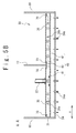
- FIG. 5B is a side sectional view of the gas room provided for the frictional resistance reducing device according to the first embodiment along the line A-A of FIG. 5A ;
- FIG. 5C is a sectional view of the gas room provided for the frictional resistance reducing device according to the first embodiment along the line B-B of FIG. 5A ;
- FIG. 5D is a sectional view of the gas room provided for the frictional resistance reducing device according to the first embodiment along the line C-C of FIG. 5A ;
- FIG. 6A is a side sectional view of a first modification of the gas room according to the first embodiment along the line A-A of FIG. 5A ;
- FIG. 6B is s sectional view of the first modification of the gas room according to the first embodiment along the line C-C of FIG. 5A ;
- FIG. 7A is a side sectional view of a second modification of the gas room according to first embodiment along the line A-A of FIG. 5A ;
- FIG. 7B is a sectional view of the second modification of the gas room according to first embodiment along the line C-C of FIG. 5A ;
- FIG. 8A is a plan view of the gas room provided for the frictional resistance reducing device according to a second embodiment of the present invention.
- FIG. 8B is a sectional view of the gas room provided for the frictional resistance reducing device according to the second embodiment of the present invention along the line D-D of FIG. 8A ;
- FIG. 8C is a sectional view of the gas room provided for the frictional resistance reducing device according to the second embodiment of the present invention along the line E-E of FIG. 8A ;
- FIG. 8D is a sectional view of the gas room provided for the frictional resistance reducing device according to the second embodiment of the present invention along the line F-F of FIG. 8A .
- a ship according to a first embodiment of the present invention is provided with a hull 10 and a frictional resistance reducing device 20 .
- the hull 10 is provided with a bow 11 , a stern 12 , and a bottom in a ship 13 .
- the propeller 14 and a rudder 15 are provided for the stern 12 .
- the frictional resistance reducing device 20 is provided with an air feeder 21 , an air supply pipe 22 and a gas room 30 .
- the air feeder 21 is a compressor or a blower.
- the air feeder 21 and the gas room 30 are connected through the air supply pipe 22 .
- the gas room 30 is provided on the side of bow 11 of the bottom of the ship 13 .
- a plurality of air blowing holes 34 a are formed in the gas room 30 to be opened in the bottom of the ship 13 .
- the frictional resistance reducing device 20 blows air from the air blowing holes 34 a into water when the ship 13 navigate.
- an air bubble flow is formed along the bottom of the ship 13 to reduce the frictional resistance of the hull 10 .
- the hull 10 is provided with longitudinal frames 17 and 18 .
- the longitudinal frames 17 and 18 and the longitudinal frame 16 to be described later are partitions which divide a space of the hull 10 into a width direction Y of the hull 10 (a direction from the port side to the starboard side).
- the gas room 30 is provided in the hull 10 to cross the longitudinal frame 17 (to pass through the longitudinal frame 17 ) and to extend to the width direction Y.
- the frictional resistance reducing device 20 is provided with a scattering member 40 which is arranged in the gas room 30 .
- the scattering member 40 crosses the longitudinal frame 17 and extends the width direction Y. Therefore, the longitudinal directions of the gas room 30 and the scattering member 40 are parallel to the width direction Y.
- X in FIG. 4 shows a longitudinal direction (a direction from the bow to the stern) of the hull 10 .
- the air supply pipe 22 is connected with the gas room 30 from an upper side. A part of the air supply pipe 22 which is connected with the gas room 30 extends into the upper and lower directions.
- the gas room 30 will be described.
- the hull 10 is further provided with the longitudinal frame 16 .
- the longitudinal frame 16 is arranged on the port side of the longitudinal frame 17 .
- the longitudinal frame 18 is arranged on the starboard side of the longitudinal frame 17 .
- the gas room 30 is provided with an upper member 31 , a longitudinal side member 32 on the side of bow 11 , a longitudinal side member 33 on the side of stern 12 , and lids 35 and 36 .
- An opening 31 a is formed in a part of the upper member 31 on the port side from the longitudinal frame 17 .
- An opening 31 b is formed in a part of the upper member 31 on the starboard side from the longitudinal frame 17 .
- the openings 31 a and 31 b connect the internal space of the gas room 30 and the internal space of the hull 10 .
- the lid 35 is attached to the opening 31 a by bolts 70 .
- the lid 36 is attached to the opening 31 b by bolts 70 . Therefore, it is possible to remove the lids 35 and 36 .
- the air supply pipe 22 is connected with the lid 35 .
- the gas room 30 is provided with a bottom member 34 in which the plurality of air blowing holes 34 a are formed.
- the bottom member 34 is formed as the bottom of the ship 13 .
- the plurality of air blowing holes 34 a are arranged in the width direction Y.
- the longitudinal frame 16 forms a port side member on the port side of the gas room 30 .
- the longitudinal frame 18 forms a starboard side member on the starboard side of the gas room 30 .
- the scattering member 40 has a block structure which is provided with a first part 41 , a second part 42 and a middle part 43 .
- the first part 41 forms a part of the scattering member 40 on the port side from the longitudinal frame 17 .
- the second part 42 forms a part of the scattering member 40 on the starboard side from the longitudinal frame 17 .
- the middle part 43 forms a part of the scattering member 40 between the first part 41 and second part 42 .
- the first part 41 has a size enough to pass through the opening 31 a .
- the first part 41 is attached to the lid 35 through supporting members 51 .
- the second part 42 has a size enough to pass through the opening 31 b .
- the second part 42 is attached to the lid 36 through supporting members 52 .
- the middle part 43 is supported by the longitudinal frame 17 through a supporting member 53 .
- the first part 41 and the second part 42 can be separated from the scattering member 40 .
- a connection port of the air supply pipe 22 and the lid 35 is arranged straightly above the scattering member 40 (the first part 41 ).
- the plurality of air blowing holes 34 a are arranged straightly below the scattering member 40 .
- a slit hole 61 is formed between the scattering member 40 and the longitudinal side member 32 to extend in the width direction Y.
- a slit hole 62 is formed between the scattering member 40 and the longitudinal side member 33 to extend in the width direction Y.
- the slit hole 61 is arranged on the side of bow 11 of the scattering member 40 .
- the slit hole 62 is arranged on the side of the stern 12 of the scattering member 40 .
- the air feeder 21 supplies air into the gas room 30 through the air supply pipe 22 .
- the air is blown from the air supply pipe 22 into the gas room 30 as a flow in a downward direction for the scattering member 40 (the first part 41 ).
- the air blown into the gas room 30 from the air supply pipe 22 hits the scattering member 40 and scatters into the width direction Y, and moreover after passing the slit hole 61 or the slit hole 62 , is blown from the air blowing holes 34 a into water. Therefore, an air bubble flow, which is uniform in the width direction Y, is formed along the bottom of the ship 13 .
- the air bubble flow which is wide in the width direction Y can be formed by the single gas room 30 because the gas room 30 crosses the longitudinal frame 17 to extend in the width direction Y. Therefore, the number of gas rooms 30 which are necessary to form the air bubble flow which covers the whole width of the bottom of the ship 13 in the width direction Y may be few, and the number of air supply pipes 22 which are provided every gas room 30 may be few. According to the present embodiment, it is not necessary to provide the many air supply pipes in the hull 10 where the space is limited.
- the opening 31 a or 31 b is provided between adjacent two of the longitudinal frames 16 to 18 . It is possible to separate the first part 41 and the second part 42 from the scattering member 40 and to take them out of the gas room 30 (in the hull 10 ) through the openings 31 a and 31 b . Therefore, the cleaning to remove marine organisms such as barnacles which are adhered to the gas room 30 and the scattering member 40 is easy at the time of the docking. Therefore, the frictional resistance reducing device 20 according to the present embodiment is superior for maintenance.
- the lid 35 and the first part 41 are coupled by the supporting member 51
- the lid 36 and the second part 42 are coupled by the supporting member 52
- the first part 41 is taken out from the gas room 30 at the same time as removing the lid 35
- the second part 42 is taken out from the gas room 30 at the same time as removing the lid 36 . Therefore, works for the maintenance can be little.
- the frictional resistance reducing device 20 according to the first modification is same as the frictional resistance reducing device 20 according to the first embodiment, excluding the following description.
- the first part 41 of the scattering member 40 is not attached to the lid 35 and the second part 42 of the scattering member 40 is not attached to the lid 36 .
- a supporting member 54 is provided for as the longitudinal frame 16 (longitudinal side member of the gas room 30 ) on the port side and a supporting member 55 is provided for the longitudinal frame 18 (longitudinal side member of the gas room 30 ) on the starboard side.
- the first part 41 is attached to the supporting member 54 and the middle part 43 by bolts 70
- the second part 42 is attached to the supporting member 55 and the middle part 43 by bolts 70 . Therefore, the first part 41 and the second part 42 can be detachable.
- the first part 41 is taken out of the gas room 30 (in the hull 10 ) through the openings 31 a after removing the lid 35 .
- the second part 42 is taken out of the gas room 30 (in the hull 10 ) through the opening 31 b after removing the lid 36 .
- the frictional resistance reducing device 20 according to the second modification is same as the above frictional resistance reducing device 20 according to the first embodiment, excluding the following explanation.
- the first part 41 of the scattering member 40 is not attached to the lid 35 and the second part 42 of the scattering member 40 is not attached to the lid 36 .
- Supporting members 56 are provided for a part of the bottom 34 on the port side from the longitudinal frame 17 and supporting members 57 are provided for a part of the bottom 34 on the starboard side from the longitudinal frame 17 .
- the first part 41 is attached to the supporting members 56 by bolts 70 and the second part 42 is attached to the supporting members 57 by bolts 70 . Therefore, the first part 41 and the second part 42 are detachable.
- the first part 41 is taken out of the gas room 30 (in the hull 10 ) through the openings 31 a after removing the lid 35 .
- the second part 42 is taken out of the gas room 30 (in the hull 10 ) through the opening 31 b after removing the lid 36 .
- air supply pipe 22 may be connected with the lid 36 in the first embodiment, and the first modification and the second modification of the present embodiment.
- the frictional resistance reducing device 20 according to the second embodiment of the present invention will be described.
- the frictional resistance reducing device 20 according to the present embodiment is same as the frictional resistance reducing device 20 according to the first embodiment, excluding the following description.
- the gas room 30 is provided with lids 37 and 38 .
- An opening is not provided for the upper member 31 of the gas room 30 and any lid attached to the opening is not provided.
- the air supply pipe 22 is connected with a part of the upper member 31 on the port side from the longitudinal frame 17 .
- An opening 33 a is formed in a part of the longitudinal side member 33 on the port side from the longitudinal frame 17 .
- An opening 33 b is formed in a part of the longitudinal side member 33 on the starboard side from the longitudinal frame 17 .
- the openings 33 a and 33 b connect the internal space of the gas room 30 and the internal space of the hull 10 , respectively.
- the lid 37 is attached to the opening 33 a by bolts 70 .
- the lid 38 is attached to the opening 33 b by bolts 70 . Therefore, the lids 37 and 38 are detachable.
- the first part 41 of the scattering member 40 has a size enough to pass through the opening 33 a and the second part 42 of the scattering member 40 has a size enough to pass though the opening 33 b .
- Supporting members 58 are provided for a part of the upper member 31 on the port side from the longitudinal frame 17 and supporting members 59 are provided for a part of the upper member 31 on the starboard side from the longitudinal frame 17 .
- the first part 41 is attached to the supporting member 58 by bolts 70 and the second part 42 is attached to the supporting member 59 by bolts 70 . Therefore, the first part 41 and the second part 42 are detachable.
- FIG. 8D shows an attachment structure of the second part 42 to the upper member 31 .
- the first part 41 is attached to the upper member 31 , like the second part 42 .
- the gas room 30 crosses the longitudinal frame 17 and extends to the width direction Y, the air bubble flow wide in the width direction Y can be formed by the single gas room 30 . Therefore, the number of gas rooms 30 which are necessary to form the air bubble flow which covers the whole width of the bottom of the ship 13 in the width direction Y may be few.
- the number of air supply pipes 22 which are provided for every gas room 30 may be few. According to the present embodiment, it is not necessary to arrange many air supply pipes in the hull 10 with a limited space.
- the opening 33 a or 33 b of the gas room 30 is provided between adjacent two of the longitudinal frames 16 to 18 . It is possible to separate the first part 41 and the second part 42 from the scattering member 40 and to take them out of the gas room 30 (in the hull 10 ) through the openings 33 a and 33 b . Therefore, the cleaning is easy to remove the marine organisms such as barnacle adhered to the gas room 30 and the scattering member 40 at the time of the docking. Therefore, the frictional resistance reducing device 20 according to the present embodiment is superior in the maintenance.
- the air supply pipe 22 is connected with a portion of the gas room 30 other than the lids 37 and 38 , the removal of the lids 37 and 38 is easy.
- the first part 41 may be supported by the longitudinal side member 16 and the middle part 43 in the gas room 30 .
- the second part 42 may be supported by the longitudinal side member 18 and the middle part 43 in the gas room 30 .
- the first part 41 and the second part 42 may be supported to the bottom 34 .
- the air supply pipe 22 may be connected with a portion of the upper member 31 on the starboard side from the longitudinal frame 17 .
- two openings may be provided for the longitudinal side member 32 , instead of that the openings 33 a and 33 b are provided for the longitudinal side member 33 .
- slit holes may be provided for the bottom 34 to extend into the width direction Y, instead of the plurality of air blowing holes 34 a.
- the gas room 30 may cross a plurality of longitudinal frames to extend into the width direction Y.
Landscapes
- Physics & Mathematics (AREA)
- Fluid Mechanics (AREA)
- Chemical & Material Sciences (AREA)
- Engineering & Computer Science (AREA)
- Combustion & Propulsion (AREA)
- Mechanical Engineering (AREA)
- Ocean & Marine Engineering (AREA)
- Cleaning Or Clearing Of The Surface Of Open Water (AREA)
- Aeration Devices For Treatment Of Activated Polluted Sludge (AREA)
- Vibration Prevention Devices (AREA)
- Filling Or Discharging Of Gas Storage Vessels (AREA)
- Separation By Low-Temperature Treatments (AREA)
Abstract
Description
- [Patent Literature 1]: JP 2008-143345A
Claims (6)
Applications Claiming Priority (3)
| Application Number | Priority Date | Filing Date | Title |
|---|---|---|---|
| JP2009-245515 | 2009-10-26 | ||
| JP2009245515A JP5314565B2 (en) | 2009-10-26 | 2009-10-26 | Ship resistance reduction device |
| PCT/JP2010/067064 WO2011052337A1 (en) | 2009-10-26 | 2010-09-30 | Ship resistance-reduction device |
Publications (2)
| Publication Number | Publication Date |
|---|---|
| US20120097089A1 US20120097089A1 (en) | 2012-04-26 |
| US8820256B2 true US8820256B2 (en) | 2014-09-02 |
Family
ID=43921765
Family Applications (1)
| Application Number | Title | Priority Date | Filing Date |
|---|---|---|---|
| US13/376,221 Expired - Fee Related US8820256B2 (en) | 2009-10-26 | 2010-09-30 | Frictional resistance reducing device of ship |
Country Status (6)
| Country | Link |
|---|---|
| US (1) | US8820256B2 (en) |
| EP (1) | EP2495163B1 (en) |
| JP (1) | JP5314565B2 (en) |
| KR (1) | KR101341747B1 (en) |
| CN (1) | CN102448807B (en) |
| WO (1) | WO2011052337A1 (en) |
Families Citing this family (17)
| Publication number | Priority date | Publication date | Assignee | Title |
|---|---|---|---|---|
| JP2014227089A (en) * | 2013-05-23 | 2014-12-08 | 三菱重工業株式会社 | Ship remodeling method and frictional resistance reduction ship |
| KR101630574B1 (en) * | 2014-04-02 | 2016-06-15 | 현대중공업 주식회사 | Air injecting apparatus protruding from bottom plate of ship toward seawater |
| KR101595701B1 (en) * | 2015-07-02 | 2016-02-19 | 현대중공업 주식회사 | Air lubrication system having inner chamber for ship |
| CN105206143B (en) * | 2015-09-11 | 2019-01-18 | 西北工业大学 | Air layers reducing resistance model and preparation method thereof based on wetability regulation |
| EP3290325B1 (en) * | 2016-08-30 | 2019-05-22 | Silverstream Technologies B.V. | Air lubrication system with a wave deflector for a vessel |
| CN106741586B (en) * | 2016-12-22 | 2019-01-04 | 浙江大学 | A kind of ship water jet constraint bubble drag-reduction structure |
| JP6655564B2 (en) * | 2017-01-31 | 2020-02-26 | 三菱重工業株式会社 | Ship friction reduction device |
| JP6655563B2 (en) * | 2017-01-31 | 2020-02-26 | 三菱重工業株式会社 | Ship friction reduction device |
| CN108128401A (en) * | 2017-11-23 | 2018-06-08 | 中国船舶科学研究中心上海分部 | The general voltage-stablizer of gas lid |
| CN108001610B (en) * | 2017-11-23 | 2024-04-23 | 中船(上海)节能技术有限公司 | Gas lubrication drag reduction and energy saving device |
| JP7412774B2 (en) * | 2017-12-22 | 2024-01-15 | オーチャライ ミカエル | Viscous drag reducing cladding |
| CN108177724A (en) * | 2018-01-12 | 2018-06-19 | 中船重工船舶设计研究中心有限公司 | A kind of voltage stabilizing cavity configuration and installation method for resistance reduction by air cavity technology |
| CN112238922A (en) * | 2019-07-17 | 2021-01-19 | 章洪 | Supercavitation high-speed ship |
| CN111959675B (en) * | 2020-08-21 | 2021-05-04 | 中国船舶科学研究中心 | A device for generating drag reduction and generation of downstream jet air layer for ships |
| CN112519953A (en) * | 2020-11-10 | 2021-03-19 | 中船重工(上海)节能技术发展有限公司 | Gas layer drag reduction ship |
| CN112793709A (en) * | 2020-12-28 | 2021-05-14 | 中船重工(上海)节能技术发展有限公司 | Air injection structure of air layer resistance reducing device, ship air layer resistance reducing system and air layer resistance reducing ship |
| CN116476971B (en) * | 2023-06-09 | 2025-04-11 | 浙江大学 | A bubble drag reduction system and a ship comprising the same |
Citations (15)
| Publication number | Priority date | Publication date | Assignee | Title |
|---|---|---|---|---|
| US780122A (en) * | 1904-04-28 | 1905-01-17 | Hans Nelson | Air apparatus for vessels. |
| GB1190621A (en) | 1967-04-10 | 1970-05-06 | John Wakelam Grundy | Improvements in or relating to Ships and Boats. |
| JPS4835557A (en) | 1971-09-07 | 1973-05-25 | ||
| WO1984004903A1 (en) | 1983-06-07 | 1984-12-20 | Sjoerd Meijer | Vessel with adjustable draught |
| JPS60139586A (en) | 1983-12-26 | 1985-07-24 | Ishikawajima Harima Heavy Ind Co Ltd | Frictional resistance reducer for shipping |
| JPH09207873A (en) | 1996-01-31 | 1997-08-12 | Yoji Kato | Micro bubble generator |
| JPH1024891A (en) | 1996-07-08 | 1998-01-27 | Ishikawajima Harima Heavy Ind Co Ltd | Ship friction reduction device |
| CN1209405A (en) | 1997-08-22 | 1999-03-03 | 石川岛播磨重工业株式会社 | Friction-reduced ship having compressed-air production apparatus, friction-reducing apparatus and gas-jetting apparatus |
| JPH11227675A (en) | 1998-02-13 | 1999-08-24 | Ishikawajima Harima Heavy Ind Co Ltd | Air blower for ship with reduced frictional resistance |
| JPH11291973A (en) | 1998-04-06 | 1999-10-26 | Ishikawajima Harima Heavy Ind Co Ltd | Air blower for ship with reduced frictional resistance |
| JPH11301570A (en) | 1998-04-20 | 1999-11-02 | Ishikawajima Harima Heavy Ind Co Ltd | Air blower for ship with reduced frictional resistance |
| US6789491B2 (en) * | 2000-04-03 | 2004-09-14 | Ishikawajima-Harima Heavy Industries Co., Ltd. | Friction reducing ship and method for reducing frictional resistance |
| JP2008143345A (en) | 2006-12-08 | 2008-06-26 | National Maritime Research Institute | Hull frictional resistance reduction device |
| US20110094435A1 (en) | 2008-11-21 | 2011-04-28 | Shinichi Takano | Device for reducing frictional resistance of ship body |
| JP4835557B2 (en) | 2007-09-14 | 2011-12-14 | トヨタ自動車株式会社 | Blow-by gas reduction device for dry sump engine |
Family Cites Families (2)
| Publication number | Priority date | Publication date | Assignee | Title |
|---|---|---|---|---|
| JPS4835557B1 (en) * | 1968-11-26 | 1973-10-29 | ||
| JP2009245515A (en) | 2008-03-31 | 2009-10-22 | Fujifilm Corp | Magnetic recording medium, surface modifier for magnetic powder, and magnetic coating material including same |
-
2009
- 2009-10-26 JP JP2009245515A patent/JP5314565B2/en active Active
-
2010
- 2010-09-30 CN CN201080023758.7A patent/CN102448807B/en not_active Expired - Fee Related
- 2010-09-30 US US13/376,221 patent/US8820256B2/en not_active Expired - Fee Related
- 2010-09-30 EP EP10826471.4A patent/EP2495163B1/en not_active Not-in-force
- 2010-09-30 KR KR1020117028699A patent/KR101341747B1/en not_active Expired - Fee Related
- 2010-09-30 WO PCT/JP2010/067064 patent/WO2011052337A1/en not_active Ceased
Patent Citations (17)
| Publication number | Priority date | Publication date | Assignee | Title |
|---|---|---|---|---|
| US780122A (en) * | 1904-04-28 | 1905-01-17 | Hans Nelson | Air apparatus for vessels. |
| GB1190621A (en) | 1967-04-10 | 1970-05-06 | John Wakelam Grundy | Improvements in or relating to Ships and Boats. |
| JPS4835557A (en) | 1971-09-07 | 1973-05-25 | ||
| WO1984004903A1 (en) | 1983-06-07 | 1984-12-20 | Sjoerd Meijer | Vessel with adjustable draught |
| JPS60139586A (en) | 1983-12-26 | 1985-07-24 | Ishikawajima Harima Heavy Ind Co Ltd | Frictional resistance reducer for shipping |
| JPH09207873A (en) | 1996-01-31 | 1997-08-12 | Yoji Kato | Micro bubble generator |
| JPH1024891A (en) | 1996-07-08 | 1998-01-27 | Ishikawajima Harima Heavy Ind Co Ltd | Ship friction reduction device |
| EP0903287A2 (en) | 1997-08-22 | 1999-03-24 | Ishikawajima-Harima Heavy Industries Co., Ltd. | Ship with reduced skin friction and gas jetting device for the same |
| CN1209405A (en) | 1997-08-22 | 1999-03-03 | 石川岛播磨重工业株式会社 | Friction-reduced ship having compressed-air production apparatus, friction-reducing apparatus and gas-jetting apparatus |
| JPH11227675A (en) | 1998-02-13 | 1999-08-24 | Ishikawajima Harima Heavy Ind Co Ltd | Air blower for ship with reduced frictional resistance |
| JPH11291973A (en) | 1998-04-06 | 1999-10-26 | Ishikawajima Harima Heavy Ind Co Ltd | Air blower for ship with reduced frictional resistance |
| JPH11301570A (en) | 1998-04-20 | 1999-11-02 | Ishikawajima Harima Heavy Ind Co Ltd | Air blower for ship with reduced frictional resistance |
| US6789491B2 (en) * | 2000-04-03 | 2004-09-14 | Ishikawajima-Harima Heavy Industries Co., Ltd. | Friction reducing ship and method for reducing frictional resistance |
| JP2008143345A (en) | 2006-12-08 | 2008-06-26 | National Maritime Research Institute | Hull frictional resistance reduction device |
| JP4835557B2 (en) | 2007-09-14 | 2011-12-14 | トヨタ自動車株式会社 | Blow-by gas reduction device for dry sump engine |
| US20110094435A1 (en) | 2008-11-21 | 2011-04-28 | Shinichi Takano | Device for reducing frictional resistance of ship body |
| CN102112366A (en) | 2008-11-21 | 2011-06-29 | 三菱重工业株式会社 | Device for reducing frictional resistance of ship body |
Non-Patent Citations (5)
| Title |
|---|
| Chinese Notice of the Opinion on Examination issued Dec. 4, 2013 in corresponding Chinese Patent Application No. 201080023758.7 with English translation. |
| International Search Report issued Dec. 21, 2010 in International (PCT) Application No. PCT/JP2010/067064. |
| Japanese Decision to Grant a Patent mailed Jun. 13, 2013 in corresponding Japanese Patent Application No. 2009-245515 with English translation. |
| Korean Decision for Grant of Patent issued Sep. 12, 2013 in corresponding Korean Patent Application No. 2011-7028699 with partial English translation. |
| Supplementary European Search Report issued Mar. 15, 2013 in corresponding European Patent Application No. 10826471.4. |
Also Published As
| Publication number | Publication date |
|---|---|
| KR20120023731A (en) | 2012-03-13 |
| JP5314565B2 (en) | 2013-10-16 |
| CN102448807A (en) | 2012-05-09 |
| CN102448807B (en) | 2015-01-28 |
| EP2495163A1 (en) | 2012-09-05 |
| EP2495163B1 (en) | 2015-04-01 |
| US20120097089A1 (en) | 2012-04-26 |
| EP2495163A4 (en) | 2013-04-17 |
| WO2011052337A1 (en) | 2011-05-05 |
| JP2011088605A (en) | 2011-05-06 |
| KR101341747B1 (en) | 2013-12-16 |
Similar Documents
| Publication | Publication Date | Title |
|---|---|---|
| US8820256B2 (en) | Frictional resistance reducing device of ship | |
| JP5714098B2 (en) | Friction resistance reduction type ship and ship friction resistance reduction device | |
| JP5606128B2 (en) | Ship bubble recovery device | |
| EP2351686B1 (en) | Hull frictional resistance reducing device | |
| JP5705486B2 (en) | Ship air lubrication system | |
| WO2014103771A1 (en) | Ship having reduced frictional resistance | |
| JP2012071632A (en) | Air lubricating system of ship | |
| CN103826967A (en) | Method for manufacturing gas-lubricated ship, and method for manufacturing gas-discharging chamber | |
| JP5581372B2 (en) | Seawater suction box and ship | |
| JP2014097752A (en) | Air blowout device for air lubrication and ship | |
| JP5448741B2 (en) | Ship resistance reduction device | |
| JP6143165B2 (en) | Ship frictional resistance reduction device | |
| JP2012017022A (en) | Wind pressure resistance reducing structure for ship, and the ship | |
| JP5829664B2 (en) | Ship resistance reduction device | |
| JP2013119368A (en) | Air supply structure to engine room of ship | |
| JP2014144776A (en) | Air bubble recovery device of watercraft | |
| JPH10100984A (en) | Ship friction reduction device | |
| JP2014113898A (en) | Craft |
Legal Events
| Date | Code | Title | Description |
|---|---|---|---|
| AS | Assignment |
Owner name: MITSUBISHI HEAVY INDUSTRIES, LTD., JAPAN Free format text: ASSIGNMENT OF ASSIGNORS INTEREST;ASSIGNORS:TAKANO, SHINICHI;MIZOKAMI, SHUJI;HIGASA, SEIJIRO;AND OTHERS;REEL/FRAME:027327/0642 Effective date: 20111125 |
|
| STCF | Information on status: patent grant |
Free format text: PATENTED CASE |
|
| FEPP | Fee payment procedure |
Free format text: PAYOR NUMBER ASSIGNED (ORIGINAL EVENT CODE: ASPN); ENTITY STATUS OF PATENT OWNER: LARGE ENTITY |
|
| MAFP | Maintenance fee payment |
Free format text: PAYMENT OF MAINTENANCE FEE, 4TH YEAR, LARGE ENTITY (ORIGINAL EVENT CODE: M1551) Year of fee payment: 4 |
|
| AS | Assignment |
Owner name: MITSUBISHI SHIPBUILDING CO., LTD., JAPAN Free format text: ASSIGNMENT OF ASSIGNORS INTEREST;ASSIGNOR:MITSUBISHI HEAVY INDUSTRIES, LTD.;REEL/FRAME:046718/0352 Effective date: 20180101 |
|
| FEPP | Fee payment procedure |
Free format text: MAINTENANCE FEE REMINDER MAILED (ORIGINAL EVENT CODE: REM.); ENTITY STATUS OF PATENT OWNER: LARGE ENTITY |
|
| LAPS | Lapse for failure to pay maintenance fees |
Free format text: PATENT EXPIRED FOR FAILURE TO PAY MAINTENANCE FEES (ORIGINAL EVENT CODE: EXP.); ENTITY STATUS OF PATENT OWNER: LARGE ENTITY |
|
| STCH | Information on status: patent discontinuation |
Free format text: PATENT EXPIRED DUE TO NONPAYMENT OF MAINTENANCE FEES UNDER 37 CFR 1.362 |
|
| FP | Lapsed due to failure to pay maintenance fee |
Effective date: 20220902 |