US8805046B2 - Method and device for correcting a shimming device - Google Patents
Method and device for correcting a shimming device Download PDFInfo
- Publication number
- US8805046B2 US8805046B2 US13/358,395 US201213358395A US8805046B2 US 8805046 B2 US8805046 B2 US 8805046B2 US 201213358395 A US201213358395 A US 201213358395A US 8805046 B2 US8805046 B2 US 8805046B2
- Authority
- US
- United States
- Prior art keywords
- characteristic curve
- symmetry
- test
- estimation
- image
- Prior art date
- Legal status (The legal status is an assumption and is not a legal conclusion. Google has not performed a legal analysis and makes no representation as to the accuracy of the status listed.)
- Active
Links
- 238000000034 method Methods 0.000 title claims abstract description 57
- 238000012360 testing method Methods 0.000 claims abstract description 227
- 230000010354 integration Effects 0.000 claims description 29
- 238000012545 processing Methods 0.000 claims description 20
- 238000013507 mapping Methods 0.000 claims description 14
- 238000001914 filtration Methods 0.000 claims description 12
- 238000001514 detection method Methods 0.000 claims description 6
- 238000003708 edge detection Methods 0.000 claims description 6
- 238000000605 extraction Methods 0.000 claims description 5
- 238000010586 diagram Methods 0.000 description 24
- 230000008569 process Effects 0.000 description 10
- 230000000694 effects Effects 0.000 description 7
- 238000002595 magnetic resonance imaging Methods 0.000 description 7
- 238000005516 engineering process Methods 0.000 description 6
- 238000003384 imaging method Methods 0.000 description 5
- 238000012986 modification Methods 0.000 description 2
- 230000004048 modification Effects 0.000 description 2
- XLYOFNOQVPJJNP-UHFFFAOYSA-N water Substances O XLYOFNOQVPJJNP-UHFFFAOYSA-N 0.000 description 2
- 238000005481 NMR spectroscopy Methods 0.000 description 1
- 230000002411 adverse Effects 0.000 description 1
- 230000008901 benefit Effects 0.000 description 1
- 230000008859 change Effects 0.000 description 1
- 238000012937 correction Methods 0.000 description 1
- 230000007613 environmental effect Effects 0.000 description 1
- 230000005284 excitation Effects 0.000 description 1
- 238000000265 homogenisation Methods 0.000 description 1
- 238000009434 installation Methods 0.000 description 1
- 238000005259 measurement Methods 0.000 description 1
- 238000001208 nuclear magnetic resonance pulse sequence Methods 0.000 description 1
- 238000005070 sampling Methods 0.000 description 1
- 230000001629 suppression Effects 0.000 description 1
Images


Classifications
-
- G—PHYSICS
- G01—MEASURING; TESTING
- G01R—MEASURING ELECTRIC VARIABLES; MEASURING MAGNETIC VARIABLES
- G01R33/00—Arrangements or instruments for measuring magnetic variables
- G01R33/20—Arrangements or instruments for measuring magnetic variables involving magnetic resonance
- G01R33/28—Details of apparatus provided for in groups G01R33/44 - G01R33/64
- G01R33/38—Systems for generation, homogenisation or stabilisation of the main or gradient magnetic field
- G01R33/387—Compensation of inhomogeneities
- G01R33/3873—Compensation of inhomogeneities using ferromagnetic bodies ; Passive shimming
Definitions
- the present embodiments relate to homogenization technology for magnetic fields.
- Magnetic fields are widely applied in measurement and imaging technologies.
- various types of magnetic resonance imaging (MRI) apparatus acquire molecular structures and structural information about the interior of human bodies, for example, by using nuclear magnetic resonance phenomena on the basis of the magnetic fields generated by magnets.
- MRI magnetic resonance imaging
- a magnet in the MRI apparatus is to provide a magnetic field with very high homogeneity in a certain specific space (e.g., within a detection area). Although this may be easily achieved at the center position of the magnet, it is very difficult to provide the homogeneity of the magnetic field at eccentric positions of the magnet.
- a shoulder coil for scanning the shoulder of a human body may be deployed at a position close to an edge of a bore of the magnet, and the main magnetic field here may be inhomogeneous, the image quality of some specific images (e.g., images by fat suppression technology and images by water excitation technology) in these parts is significantly lowered.
- a shimming device e.g., a shim shell
- a shimming device may be placed in the magnet of the MRI apparatus, so as to compensate for the lack of homogeneity in the main magnetic field (e.g., B0 field).
- a method for compensating an inhomogeneous magnetic field is proposed in Chinese patent application no. 200810239127.3.
- a local coil for magnetic resonance equipment is proposed in Chinese patent application no. 200710195529.3, with a second coil in the local coil carrying out a shimming process on the area where the local coil is located.
- the local coil is provided with relatively poor shimming effects in some areas (e.g., in an area that is non-homocentric with the main magnetic field).
- the shimming device may be formed by some passive shimming pieces or shimming coils. Since the change of the main magnetic field at eccentric positions (e.g., edge positions) of the magnet is relatively fast, this makes the shimming effects of the shimming device quite sensitive to the deployment accuracy of the shimming device. In other words, better shimming effects may be provided only if the shimming device is deployed accurately at a position passing through the center of the cross section of the magnet.
- a laser mark is provided on the shimming device, and the shimming device with the laser mark is installed onto a test bed (e.g., a patient table (PTAB)).
- the laser mark on the shimming device is positioned using a laser emitted from the MRI apparatus, and the test bed with the shimming device is moved to a predetermined position according to the positioning point so as to locate the shimming device on the test bed at a center of the cross section of the magnet.
- the shimming device should be exactly located at the center position of the cross section of the magnet.
- the present embodiments may obviate one or more of the drawbacks or limitations in the related art.
- a method and a system for correcting a shimming device so as to obtain an optimum deployment point of the shimming device and to achieve better shimming effects are provided.
- a method for correcting a shimming device includes, for each test position of the shimming device, acquiring a phase image in a coronal plane direction of a phantom at the test position. The method also includes extracting an internal contour line in the phase image, mapping the internal contour line onto a rectangular coordinate system or a polar coordinate system to obtain a corresponding characteristic curve, and making an estimation of the degree of symmetry of the characteristic curve to obtain an image symmetry estimation result at the test position. The method includes selecting the test position with the best image symmetry estimation result as an optimum deployment point of the shimming device according to the obtained image symmetry estimation result at each test position.
- a device for correcting a shimming device includes a test position symmetry estimation unit that is for acquiring, for each of the test positions of the shimming device, a phase image in the coronal plane direction of a phantom at the test position and extracting an internal contour line in the phase image.
- the test position symmetry estimation unit is also for mapping the internal contour line onto a rectangular coordinate system or a polar coordinate system to obtain a corresponding characteristic curve and making an estimation of the a degree of symmetry of the characteristic curve to obtain an image symmetry estimation result at the test position.
- the device also includes an optimum deployment point determination unit that is for selecting the test position with the best image symmetry estimation result as an optimum deployment point of the shimming device according to the image symmetry estimation result at each test position obtained by the test position symmetry estimation unit.
- the test position with the best image symmetry estimation result may be selected from the image symmetry estimation results corresponding to the various test positions as the optimum deployment point of the shimming device according to the relationship between image symmetry and magnetic field distribution. Better shimming effects are achieved by deploying the shimming device at the optimum deployment point.
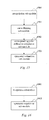
- FIG. 1 is a flow chart of one embodiment of a method for correcting a shimming device
- FIG. 2 a is an example phase image acquired in the coronal plane direction of a phantom
- FIG. 2 b is an example amplitude image acquired in the coronal plane direction of the phantom
- FIG. 2 c is an example image mask obtained on the basis of the amplitude image shown in FIG. 2 b;
- FIG. 2 e shows all the edge lines extracted from the phase image shown in FIG. 2 d;
- FIG. 4 is a schematic diagram of the flow of one embodiment of a method for making an estimation of left-right similarity in act 101 in FIG. 1 ;
- FIG. 5 a is an example interpolated characteristic curve obtained by carrying out interpolation processing on the characteristic curve shown in FIG. 2 f;
- FIG. 5 b is an example flipped characteristic curve obtained by performing a left-right flip of the characteristic curve shown in FIG. 5 a;
- FIG. 6 is a schematic diagram of example estimation results of left-right similarity at 21 test positions of the shimming device
- FIG. 7 is a schematic diagram of example integration estimation results at 21 test positions of the shimming device.
- FIG. 8 is a schematic diagram of the flow of one embodiment of an implementing method of act 101 in FIG. 1 ;
- FIG. 9 is a schematic diagram of the flow of another embodiment of an implementing method of act 101 in FIG. 1 ;
- FIG. 11 is a schematic diagram of the internal structure of one embodiment of a test position symmetry estimation unit in the device shown in FIG. 10 ;
- FIG. 16 is another schematic diagram of the internal structure of one embodiment of the symmetry estimation module in a test position symmetry estimation unit.
- the shimming device position obtained by laser positioning may be taken as an initial position of the shimming device.
- a position compensation value for the initial value of the shimming device obtained by laser positioning may be obtained according to the optimum deployment point of the shimming device.
- the position compensation value stored in the system, and when in use, the shimming device, is adjusted from the initial position to the optimum deployment point according to the position compensation value.
- FIG. 1 is an exemplary flow chart of a method for correcting a shimming device. As shown in FIG. 1 , the flow includes the following acts.
- a phase image in the coronal plane direction of a phantom is acquired at the test position, and an internal contour line in the phase image is extracted.
- the internal contour line is mapped onto a rectangular coordinate system or a polar coordinate system (the polar coordinate system is taken as an example hereinafter) to obtain a corresponding characteristic curve, and an estimation of a degree of symmetry of the characteristic curve is made to obtain an image symmetry estimation result at the test position.
- each of the test positions of the shimming device may be determined according to practical needs.
- An initial position of the shimming device may be obtained on the basis of laser positioning, and one or more positions within a predetermined range at each side of an initial position along a magnet aperture direction may be selected.
- the test positions may be predetermined statically, and the test positions may also be determined dynamically according to certain rules. For example, all position points obtained by taking the initial position as a center and taking 1 mm as a test interval within the range of ⁇ 10 mm along the magnet aperture direction may be statically determined as the test positions.
- the phase image corresponding to a magnetic field with a relatively symmetric distribution should have 9 consecutive wave troughs. Therefore, whether there are 9 consecutive wave troughs may be detected in the acquired characteristic curve of the phase image, so as to obtain a desired image by filtering. Accordingly, possible test positions may also be determined dynamically; a detailed description of this application is given below.
- the test position with the best image symmetry estimation result is selected as the optimum deployment point of the shimming device according to the obtained image symmetry estimation result at each test position.
- the shimming device may be adjusted to the optimum deployment point.
- a position compensation value for the initial value of the shimming device obtained by laser positioning may be obtained according to the optimum deployment point of the shimming device.
- the position compensation value is stored in the system.
- the shimming device is adjusted from the initial position obtained by the laser positioning to the optimum deployment point according to the position compensation value.
- a pulse sequence with phase imaging characteristics may be used.
- a 1.5 T MRI system may be used, a first echo time (TE 1 ) is set as 4.7 ms, and a second echo time (TE 2 ) is set as 9.46 ms.
- 2D two-dimensional
- 2D two-dimensional distortion correction and phase encoding in a head-to-foot (HF) direction
- HF head-to-foot
- a sampling rate of at least 50% and relatively large readout bandwidth e.g., 500 Hz/pixel
- a 7100 ml bottle-shaped phantom is used, and a bracket of a shoulder coil is used to assemble the shimming device.
- the phantom is deployed at the center (e.g., corresponding to the initial position of the shimming device) in the Z direction (e.g., a magnet aperture direction) by positioning the laser on a laser mark of the shimming device.
- a phase image in the coronal plane direction of the phantom at this position is acquired to obtain the phase image in the coronal plane direction of the phantom, as shown in FIG. 2 a .
- the following processing gives corresponding examples based on the phase image.
- act 101 there may be many methods for extracting an internal contour line of the phase image.
- One implementation is described in detail below; as shown in FIG. 3 , the one implementation includes the following acts.
- an amplitude image in the coronal plane direction of the phantom at a test position is acquired at the same time as acquiring the phase image in the coronal plane direction of the phantom at the test position.
- FIG. 2 b is an example amplitude image acquired in the coronal plane direction of the phantom.
- the amplitude image corresponding to the phase image may be one diagram, or the amplitude image may be two diagrams. This is determined according to practical needs.
- an image mask is determined by using a grayscale histogram of the amplitude image.
- FIG. 2 c is an example image mask obtained on the basis of the amplitude image shown in FIG. 2 b.
- FIG. 2 d is an example phase image obtained after filtering the noise of the phase image shown in FIG. 2 a by using the image mask shown in FIG. 2 c.
- acts 302 and 303 the image processing technology in the prior art may be used to carry out particular processing that will not be described here redundantly.
- edges of the phase image after noise filtration are detected to obtain all edge lines of the phase image.
- FIG. 2 e shows all the edge lines extracted from the example phase image shown in FIG. 2 d.
- a currently available image processing technology may be used to detect the edges of the phase image (e.g., differential operation is used to detect the edges of the phase image to obtain all edge lines of the phase image).
- an internal contour line is extracted from all the edges lines.
- An example internal contour line from all the edge lines is as shown in FIG. 2 e.
- some scanning lines may be set to scan all the edge lines from an inner side to an outer side.
- a first strip line where the scanning lines meet is the internal contour line.
- the above process of extracting the internal contour line in the phase image is one way for processing in the present embodiments. Detection areas of the phase image may be reduced by carrying out denoising processing on the phase image. During practical application, the edges of the phase image may also be directly detected to obtain all the edge lines of the phase image. The internal contour line is extracted from all the edges lines. There is no need to carry out the denoising processing on the phase image.
- the process of mapping the internal contour line onto the polar coordinate system to obtain a corresponding characteristic curve may be as follows: a reference point is set at a position that is inclined to the inner side at the center of the internal contour line, and the internal contour line is mapped onto the polar coordinate system according to a distance between the reference point and the internal contour line and an angle between the internal contour line and a horizontal axis to obtain a corresponding characteristic curve.
- the characteristic curve is a characteristic curve obtained by mapping the internal contour line shown in FIG. 2 e onto a polar coordinate system.
- the characteristic curve may also be filtered and smoothed.
- act 101 there may be many methods for making an estimation of the degree of symmetry of the characteristic curve. Two methods for making the estimation of the degree of symmetry are described below.
- FIG. 4 shows a schematic diagram of the flow of one embodiment of a method for making an estimation of left-right similarity.
- the method for making the estimation of left-right similarity includes the following acts.
- an interpolation operation is carried out on the characteristic curve to obtain an interpolated characteristic curve.
- An example of the interpolated characteristic curve is shown in FIG. 5 .
- FIG. 5 a is an interpolated characteristic curve obtained by carrying out interpolation processing on the characteristic curve shown in FIG. 2 f.
- the particular interpolation operation method may be selected according to practical needs.
- the interpolation operation may be carried out on the characteristic curve shown in FIG. 2 f by taking 0.1 as the interval.
- the interpolation curve may be trimmed between ⁇ 80° and 80° to obtain an interpolated curve shown in FIG. 5 a.
- the interpolated characteristic curve is left-right flipped to obtain a flipped characteristic curve.
- FIG. 5 b is a flipped characteristic curve obtained by performing a left-right flip of the characteristic curve shown in FIG. 5 a.
- FIG. 5 c is a schematic diagram of calculation of the differences in position between the corresponding points on the characteristic curve before flipping shown in FIG. 5 a and the characteristic curve after flipping shown in FIG. 5 b.
- an estimation of the degree of symmetry of the characteristic curve is obtained according to the difference value for each corresponding point position.
- a mean square deviation of each difference value may be calculated, and the mean square deviation is taken as the symmetry estimation result of the characteristic curve.
- a sum of the absolute values of each of the difference values may also be calculated, and the sum of the absolute values of the difference values is taken as a symmetry estimation result of the characteristic curve.
- the process of left-right similarity estimation is, as shown in FIG. 4 , in consideration of the fact that the characteristic curve obtained by mapping the internal contour line onto the polar coordinate system may be formed by several discrete points, and the interval between one point and another point may not be identical among these discrete points.
- an interpolation operation is carried out on the characteristic curve in the above process (e.g., the above act 401 is performed to acquire an identical point interval).
- the above process is only one implementation for making an estimation of left-right similarity in the present embodiments. In practical applications, it is also possible not to perform act 401 .
- the characteristic curve that is not interpolated e.g., the characteristic curve, as shown in FIG. 2 f
- the positions of the plurality of set corresponding points may be the positions of corresponding points that are in the characteristic curve before flipping and after flipping.
- the phase image corresponding to the result that has the smallest value is selected from the symmetry estimation results (e.g., the mean square deviation of the difference value of each corresponding point and the sum of the absolute values of difference values of the corresponding points).
- the phase image with the best degree of symmetry, and the test position of the shimming device corresponding to the phase image with the best degree of symmetry is the optimum deployment position of the shimming device.
- FIG. 6 shows the estimation results of left-right similarity at 21 test positions of the shimming device within a ⁇ 10 mm range of the center point.
- the center point is the initial position obtained by laser positioning.
- the phase images of the coronal plane of the phantom at the test positions corresponding respectively to a minimum value and a second minimum value of the similarity estimation results are shown in the FIG. 6 .
- the phase image of the coronal plane of the phantom at the test position corresponding to the minimum value of the similarity estimation results has the best degree of symmetry; therefore, the test position of the shimming device corresponding thereto is the optimum deployment point of the shimming device.
- the curve within a set range at each side of the center point of the characteristic curve may also be integrated to obtain an estimation of the degree of symmetry of the characteristic curve according to the integration results.
- the range of the curve may be set according to practical applications; for example, as to the curve shown in FIG. 2 f , the set range thereof may be the curves within a range from ⁇ 20° to 20° in the polar coordinate system.
- the phase image corresponding to the result that has the biggest value is selected therefrom as the phase image with the best degree of symmetry.
- the test position of the shimming device corresponding to the phase image is the optimum deployment position of the shimming device.
- FIG. 7 shows the estimation results of left-right similarity at 21 test positions of the shimming device within a ⁇ 10 mm range of the center point.
- the center point is the initial position obtained by laser positioning.
- the phase images of the coronal plane of the phantom at the test positions corresponding respectively to the maximum value and the second maximum value of the similarity estimation results are shown in FIG. 7 .
- the phase image of the coronal plane of the phantom at the test position corresponding to the maximum value of the similarity estimation results has the best degree of symmetry, and the test position of the shimming device corresponding thereto should be the optimum deployment position of the shimming device.
- a phase image in the coronal plane direction of the phantom at a test position is obtained.
- An internal contour line in the phase image at the test position is extracted.
- the internal contour line is mapped onto a polar coordinate system to obtain a corresponding characteristic curve, and an estimation of the degree of symmetry of the characteristic curve is made to obtain an image symmetry estimation result at the test position.
- a phase image in the coronal plane direction of the phantom at a next test position is acquired, and the above operation is repeated on the phase image at the next test position.
- the phase image in the coronal plane direction of the phantom at each test position is obtained first (e.g., the phase images in the coronal plane direction of the phantom at a plurality of test positions are obtained).
- An internal contour line in each phase image is extracted respectively.
- the extracted internal contour lines are mapped onto a polar coordinate system to obtain corresponding characteristic curves.
- the degree of symmetry of each characteristic curve is estimated respectively to obtain an image symmetry estimation result at each corresponding test position.
- the acquisition of the phase image, the extraction of the internal contour line, the generation of the characteristic curve, and the image symmetry estimation at each test position may also be carried out in parallel or in a cross-over way.
- the implementation to be used may be determined according to practical needs.
- FIG. 1 Two implementations of at 101 shown in FIG. 1 are described below in detail in conjunction with FIGS. 8 and 9 , respectively.
- FIG. 8 is a schematic diagram of the flow of an implementing method of act 101 in FIG. 1 . As shown in FIG. 8 , this flow includes the following acts.
- an initial position is determined within a predetermined test range, and the determined initial position is taken as the current test position of the shimming device.
- the initial position may be an initial position of the shimming device obtained on the basis of laser positioning.
- the test range may be a predetermined range at each side of the initial position.
- the initial position and the test range may also be an initial position and test range decided in advance by another method.
- an internal contour line in the phase image is extracted, and the internal contour line is mapped onto a polar coordinate system to obtain a corresponding characteristic curve.
- the degree of symmetry of the characteristic curve is estimated to obtain an image symmetry estimation result at the current test position.
- act 805 whether there is a next test position within the test range is determined. If there is, then act 806 is performed; the next test position is taken as the current test position, and act 802 is returned to and performed. Otherwise, act 102 is performed.
- the method may further include 804 a .
- the number of wave troughs in the characteristic curve is detected. If the number of wave troughs in the characteristic curve is 9, then a fine search is carried out, and the test interval is set as a first test interval (e.g., 1 mm). Otherwise, a rough search is carried out, and the test interval is set as a second test interval (e.g., 2 mm). In this case, the second test interval is bigger than the first test interval.
- Act 804 a may be performed before act 804 or act 804 a may also be performed after act 804 . If act 804 a is performed before act 804 and if the number of wave troughs in the characteristic curve is 9, then act 804 is performed. Otherwise, act 804 may not be performed.
- the next test position may be determined according to the current test position and the first test interval. For example, taking the situation where the interval is 1 mm as an example, it may be determined in act 805 that the position that is the current test position +1 mm and the position that is the current test position ⁇ 1 mm are taken as next test positions respectively. If the two test positions are located within the predetermined range at each side of the initial position, then the two test positions are taken as current test positions, respectively. Act 802 is returned to and performed (e.g., the operations of acts 802 to 804 are performed on the two test positions, respectively). Otherwise, act 102 is performed.
- FIG. 9 is a schematic diagram of the flow of another implementing method shown at act 101 in FIG. 1 . As shown in FIG. 9 , this flow includes the following acts.
- the test positions are the preset test positions.
- the test positions may be the initial position of the shimming device obtained on the basis of laser positioning and each of the positions within 10 mm at each side of the initial position at 1 mm intervals (e.g., 21 test positions in total).
- Acts 902 and 903 may further includes detecting the number of wave troughs in each characteristic curve and taking the characteristic curve with a trough number of 9 as a characteristic curve to be used for making the estimation.
- the symmetry estimation may be carried out only on each characteristic curve to be used for making the estimation in act 903 .
- FIG. 10 is an exemplary structural diagram of one embodiment of a device for correcting a shimming device. As shown in FIG. 10 , the device includes a test position symmetry estimation unit 1001 and an optimum deployment point determination unit 1002 .
- An optimum deployment point determination unit 1002 is used for selecting the test position with the best image symmetry estimation result as the optimum deployment point of the shimming device according to the image symmetry estimation result at each test position obtained by the test position symmetry estimation unit 1001 .
- the device for correcting the shimming device may further include an adjustment unit.
- the adjustment unit is used for adjusting the shimming device to the above optimum deployment point.
- the adjustment unit may obtain a position compensation value for an initial value of the shimming device obtained by laser positioning according to the optimum deployment point of the shimming device obtained by the optimum deployment point determination unit 1002 .
- the adjustment unit may store the position compensation value in the system. When measuring or imaging by using a magnetic field, the adjustment unit adjusts the shimming device from the initial position obtained by laser positioning to the optimum deployment point according to the position compensation value.
- the device shown in FIG. 10 may be used for implementing the method shown in FIG. 1 . Accordingly, the particular operation process of the test position symmetry estimation unit 1001 may be in accordance with the operation process in act 101 shown in FIG. 1 . The operation process of the optimum deployment point determination unit 1002 may be in accordance with the operation process in act 102 shown in FIG. 1 .
- FIG. 11 shows a schematic diagram of the internal structure of the test position symmetry estimation unit 1001 .
- the test position symmetry estimation unit 1001 includes a test position determination module 1101 , an image acquisition module 1102 , an image processing module 1103 , and a symmetry estimation module 1104 .
- the test position determination module 1101 is used for determining a current test position from each of the test positions of the shimming device.
- the test position determination module 1101 may take the initial position of the shimming device obtained on the basis of laser positioning as the current test position of the shimming device when testing initially. When it is determined that there is a next test position within the predetermined range at each side of the initial position (e.g., within the test range), the next test position is taken as the current test position.
- the test position determination module 1101 may also take each preset test position, respectively, as the current test position in succession. The implementation that is used may be determined according to practical needs.
- the image processing module 1103 is used for extracting an internal contour line in the phase image and mapping the internal contour line onto a polar coordinate system to obtain a corresponding characteristic curve.
- the symmetry estimation module 1104 is used for making an estimation of the degree of symmetry of the characteristic curve to obtain an image symmetry estimation result at the corresponding test position.
- the test position symmetry estimation unit 1001 may be as shown in FIG. 12 .
- the test position symmetry estimation unit 1001 may further include a first wave trough point detection module 1105 for detecting the number of wave troughs in the characteristic curve. If the number of wave troughs in the characteristic curve is 9, then a fine search is carried out, and the test interval is set as a first test interval. Otherwise, a rough search is carried out, and the test interval is set as a second test interval. The second test interval is bigger than the first test interval. Accordingly, the test position determination module 1101 determines a next test position according to the current test position and the first test interval or determines a next test position according to the current test position and the second test interval. If the next test position is located within the test range (e.g., within the predetermined range at each side of the initial position), the next test position is taken as the current test position.
- the test range e.g., within the predetermined range at each side of the initial position
- test position symmetry estimation unit 1001 may be as shown in FIG. 13 .
- the test position symmetry estimation unit 1001 may further include a second wave trough point detection module 1106 for detecting the number of wave troughs in the characteristic curve and taking a characteristic curve having a trough number of 9 as a characteristic curve to be used for making the estimation.
- the symmetry estimation module 1104 is used for making an estimation of the degree of symmetry of the characteristic curve to be used for making the estimation to obtain an image symmetry estimation result at the corresponding test position.
- the internal structure of the image processing module 1103 may be as shown in FIG. 14 .
- the image processing module 1103 may include an edge detection sub-module 1401 and a contour line extraction sub-module 1402 .
- the edge detection sub-module 1401 is used for detecting edges of the phase image to obtain all edge lines of the phase image.
- the contour line extraction sub-module 1402 is used for extracting an internal contour line from all the edge lines.
- the image acquisition module 1102 may further acquire an amplitude image in the coronal plane direction of the phantom at the test position while acquiring the phase image in the coronal plane direction of the phantom at the current test position.
- the image processing module 1103 may further include a mask determination sub-module 1403 and a noise filtration sub-module 1404 (referring to the dotted line portion in FIG. 14 ).
- the mask determination sub-module 1403 is used for determining an image mask by using a grayscale histogram of the amplitude image.
- the noise filtration sub-module 1404 is used for filtering the noise of the phase image in the coronal plane direction of the phantom at the test position by using the image mask to obtain a phase image after noise filtration.
- the edge detection sub-module 1401 is used for detecting edges of the phase image after noise filtration to obtain all edge lines of the phase image.
- the symmetry estimation module 1104 may estimate the degree of symmetry of the characteristic curve by using various symmetry estimation methods. For example, a left-right similarity estimation method or integration estimation method may be used.
- FIG. 15 shows a schematic diagram of the internal structure of the symmetry estimation module 1104 . As shown by the solid line portion in FIG. 15 , the symmetry estimation module 1104 includes a curve flipping sub-module 1501 , a corresponding point difference calculation sub-module 1502 , and a symmetry estimation sub-module 1503 .
- the curve flipping sub-module 1501 is used for performing a left-right flip of the characteristic curve to obtain a flipped characteristic curve.
- the corresponding point difference calculation sub-module 1502 is used for calculating position differences between a plurality of set corresponding points on the characteristic curve before flipping and after flipping to obtain the difference value of each corresponding point position.
- the symmetry estimation sub-module 1503 is used for obtaining an estimation of the degree of symmetry of the characteristic curve according to the difference value of each corresponding point position.
- the symmetry estimation sub-module 1503 may further be as shown by the dotted line portion in FIG. 15 .
- the symmetry estimation sub-module 1503 may include an interpolation sub-module 1504 for carrying out interpolation operation on the characteristic curve to obtain an interpolated characteristic curve.
- the curve flipping sub-module 1501 is used for performing a left-right flip of the interpolated characteristic curve to obtain a flipped characteristic curve.
- FIG. 16 shows another schematic diagram of the internal structure of the symmetry estimation module.
- the symmetry estimation module 1104 includes an integration sub-module 1601 and a symmetry acquisition sub-module 1602 .
- the integration sub-module 1601 is used for integrating the curve within a set range located at each side of the center point of the characteristic curve to obtain integration results.
- the symmetry acquisition sub-module 1602 is used for obtaining an estimation of the degree of symmetry of the characteristic curve according to the integration results.
Landscapes
- Physics & Mathematics (AREA)
- Condensed Matter Physics & Semiconductors (AREA)
- General Physics & Mathematics (AREA)
- Magnetic Resonance Imaging Apparatus (AREA)
- Image Analysis (AREA)
Abstract
Description
Claims (19)
Applications Claiming Priority (3)
| Application Number | Priority Date | Filing Date | Title |
|---|---|---|---|
| CN201110027355.6A CN102621509B (en) | 2011-01-26 | 2011-01-26 | Shimming device correction method and apparatus thereof |
| CN201110027355 | 2011-01-26 | ||
| CNCN201110027355.6 | 2011-01-26 |
Publications (2)
| Publication Number | Publication Date |
|---|---|
| US20130308869A1 US20130308869A1 (en) | 2013-11-21 |
| US8805046B2 true US8805046B2 (en) | 2014-08-12 |
Family
ID=46561539
Family Applications (1)
| Application Number | Title | Priority Date | Filing Date |
|---|---|---|---|
| US13/358,395 Active US8805046B2 (en) | 2011-01-26 | 2012-01-25 | Method and device for correcting a shimming device |
Country Status (2)
| Country | Link |
|---|---|
| US (1) | US8805046B2 (en) |
| CN (1) | CN102621509B (en) |
Cited By (1)
| Publication number | Priority date | Publication date | Assignee | Title |
|---|---|---|---|---|
| US20130285658A1 (en) * | 2012-04-27 | 2013-10-31 | Siemens Aktiengesellschaft | Water/fat image identification method and device, and harmonization method and device |
Families Citing this family (5)
| Publication number | Priority date | Publication date | Assignee | Title |
|---|---|---|---|---|
| CN103592610B (en) * | 2013-11-26 | 2015-12-30 | 中国科学院武汉物理与数学研究所 | A kind of automatic search method for shimming based on absorption lineshape second moment |
| CN105662412B (en) * | 2015-12-29 | 2019-09-10 | 东软医疗系统股份有限公司 | A kind of method for shimming first order of magnetic resonance system, device and equipment |
| CN109407022B (en) * | 2018-10-25 | 2020-10-09 | 上海联影医疗科技有限公司 | Method and device for controlling magnetic field drift and storage medium |
| CN109741335B (en) * | 2018-11-28 | 2021-05-14 | 北京理工大学 | Method and device for segmenting vascular wall and blood flow area in blood vessel OCT image |
| CN110074786B (en) * | 2019-04-30 | 2022-12-06 | 上海东软医疗科技有限公司 | Nuclear magnetic resonance shimming method and device, computing equipment and nuclear magnetic resonance imaging system |
Citations (9)
| Publication number | Priority date | Publication date | Assignee | Title |
|---|---|---|---|---|
| US20040164737A1 (en) * | 2002-12-02 | 2004-08-26 | Thorsten Feiweier | Method for determining the B1 field strength in MR measurements |
| US20050156593A1 (en) * | 2003-11-28 | 2005-07-21 | Stefan Assmann | Method and magnetic resonance tomography apparatus for producing phase-coded flow images |
| US20060253017A1 (en) * | 2005-03-23 | 2006-11-09 | O'donnell Thomas | System and method for tracking and classifying the left ventricle of the heart using cine-delayed enhancement magnetic resonance |
| CN101290344A (en) | 2007-04-18 | 2008-10-22 | 西门子磁体技术有限公司 | Improved shimming for imaging magnet |
| CN101452065A (en) | 2007-12-04 | 2009-06-10 | 西门子(中国)有限公司 | Partial coil in magnetic resonance equipment, the magnetic resonance equipment and imaging method |
| CN101533701A (en) | 2008-12-09 | 2009-09-16 | 中国航天科技集团公司第五研究院第五一四研究所 | Compensation method for non-uniform magnetic field |
| US20110044524A1 (en) * | 2008-04-28 | 2011-02-24 | Cornell University | Tool for accurate quantification in molecular mri |
| US20110176714A1 (en) * | 2009-12-16 | 2011-07-21 | Rares Salomir | Method to determine a background phase in phase image data sets |
| US20120133362A1 (en) * | 2010-11-25 | 2012-05-31 | Patrick Gross | Magnetic resonance method and system for phase correction of magnetic resonance signals originating in mixed tissue |
Family Cites Families (4)
| Publication number | Priority date | Publication date | Assignee | Title |
|---|---|---|---|---|
| JP3353826B2 (en) * | 1999-06-24 | 2002-12-03 | ジーイー横河メディカルシステム株式会社 | Magnetic field inhomogeneity measurement device, phase correction device, and magnetic resonance imaging device |
| US6472872B1 (en) * | 2001-06-29 | 2002-10-29 | Mayo Foundation For Medical Education And Research | Real-time shimming of polarizing field in magnetic resonance system |
| CN101936706B (en) * | 2009-06-30 | 2012-10-17 | 西门子(深圳)磁共振有限公司 | Shimming frame position correction method and device |
| CN101937067B (en) * | 2009-06-30 | 2013-03-13 | 西门子(深圳)磁共振有限公司 | Method and device for calibrating position of shimming frame |
-
2011
- 2011-01-26 CN CN201110027355.6A patent/CN102621509B/en active Active
-
2012
- 2012-01-25 US US13/358,395 patent/US8805046B2/en active Active
Patent Citations (10)
| Publication number | Priority date | Publication date | Assignee | Title |
|---|---|---|---|---|
| US20040164737A1 (en) * | 2002-12-02 | 2004-08-26 | Thorsten Feiweier | Method for determining the B1 field strength in MR measurements |
| US20050156593A1 (en) * | 2003-11-28 | 2005-07-21 | Stefan Assmann | Method and magnetic resonance tomography apparatus for producing phase-coded flow images |
| US20060253017A1 (en) * | 2005-03-23 | 2006-11-09 | O'donnell Thomas | System and method for tracking and classifying the left ventricle of the heart using cine-delayed enhancement magnetic resonance |
| CN101290344A (en) | 2007-04-18 | 2008-10-22 | 西门子磁体技术有限公司 | Improved shimming for imaging magnet |
| US20080258729A1 (en) | 2007-04-18 | 2008-10-23 | Siemens Magnet Technology Ltd. | Shim for Imaging Magnets |
| CN101452065A (en) | 2007-12-04 | 2009-06-10 | 西门子(中国)有限公司 | Partial coil in magnetic resonance equipment, the magnetic resonance equipment and imaging method |
| US20110044524A1 (en) * | 2008-04-28 | 2011-02-24 | Cornell University | Tool for accurate quantification in molecular mri |
| CN101533701A (en) | 2008-12-09 | 2009-09-16 | 中国航天科技集团公司第五研究院第五一四研究所 | Compensation method for non-uniform magnetic field |
| US20110176714A1 (en) * | 2009-12-16 | 2011-07-21 | Rares Salomir | Method to determine a background phase in phase image data sets |
| US20120133362A1 (en) * | 2010-11-25 | 2012-05-31 | Patrick Gross | Magnetic resonance method and system for phase correction of magnetic resonance signals originating in mixed tissue |
Cited By (2)
| Publication number | Priority date | Publication date | Assignee | Title |
|---|---|---|---|---|
| US20130285658A1 (en) * | 2012-04-27 | 2013-10-31 | Siemens Aktiengesellschaft | Water/fat image identification method and device, and harmonization method and device |
| US9869736B2 (en) * | 2012-04-27 | 2018-01-16 | Siemens Aktiengesellschaft | Water/fat image identification method and device, and harmonization method and device |
Also Published As
| Publication number | Publication date |
|---|---|
| CN102621509B (en) | 2014-11-26 |
| CN102621509A (en) | 2012-08-01 |
| US20130308869A1 (en) | 2013-11-21 |
Similar Documents
| Publication | Publication Date | Title |
|---|---|---|
| US8805046B2 (en) | Method and device for correcting a shimming device | |
| US8643364B2 (en) | Magnetic resonance imaging apparatus | |
| US20120217966A1 (en) | Method for compensating for eddy current fields in magnetic resonance images | |
| RU2672151C2 (en) | Correction of epi extraneous echoes | |
| US10321114B2 (en) | Testing 3D imaging systems | |
| CN102038502A (en) | Correction of distortions in diffusion-weighted magnetic resonance imaging | |
| CN103376433B (en) | Method and system for correcting image distortion and magnetic resonance imaging device | |
| CN107153169A (en) | A kind of many echo method for separate imaging of water and fat of stable state precession gradient | |
| KR101439213B1 (en) | Method for 3D Location determination in single image using Rational Polynomial Coefficients information of stereo satellite images | |
| KR20030064641A (en) | Method for magnetic resonance imaging with automatic adaptation of the measuring field | |
| US9279872B2 (en) | Method for determining a set of B1 field maps | |
| CN106249184B (en) | A kind of dynamic auto method for shimming for magnetic resonance imaging | |
| KR101663651B1 (en) | Method for conducting a magnetic resonance examination including prospective correction of movements and a magnetic resonance system for the purpose | |
| KR20130108151A (en) | Method to acquire mr data in a predetermined volume segment of an examination subject by means of a magnetic resonance system, and corresponding magnetic resonance system | |
| US10018700B2 (en) | Correcting for main magnetic field inhomogeneity in MRI scanners | |
| US20210123993A1 (en) | Magnetic resonance imaging method and system and computer-readable storage medium | |
| KR101036046B1 (en) | Method for correcting distortions in an epi image produced by an ultra high field mri system | |
| JP6433653B2 (en) | Magnetic resonance imaging apparatus and coil selection support method in magnetic resonance imaging | |
| CN107907846B (en) | Eddy current correction method and device, mobile terminal and readable storage medium | |
| US10429471B2 (en) | MRI with variable density sampling | |
| JP7245076B2 (en) | MAGNETIC RESONANCE IMAGING APPARATUS AND MAGNETIC RESONANCE IMAGING METHOD | |
| JP4927316B2 (en) | Magnetic resonance method | |
| US20200151919A1 (en) | Method for mr image reconstruction and mr system | |
| CN104000589A (en) | Positioning method and positioning device of magnetic resonance imaging system | |
| CN110074786A (en) | Nuclear magnetic resonance method for shimming, calculates equipment and MRI system at device |
Legal Events
| Date | Code | Title | Description |
|---|---|---|---|
| AS | Assignment |
Owner name: SIEMENS AKTIENGESELLSCHAFT, GERMANY Free format text: ASSIGNMENT OF ASSIGNORS INTEREST;ASSIGNOR:SIEMENS SHENZHEN MAGNETIC RESONANCE LTD.;REEL/FRAME:033177/0500 Effective date: 20120830 Owner name: SIEMENS SHENZHEN MAGNETIC RESONANCE LTD., CHINA Free format text: ASSIGNMENT OF ASSIGNORS INTEREST;ASSIGNOR:BIN, DAI RUI;REEL/FRAME:033177/0503 Effective date: 20121113 Owner name: SIEMENS SHENZHEN MAGNETIC RESONANCE LTD., CHINA Free format text: ASSIGNMENT OF ASSIGNORS INTEREST;ASSIGNORS:HE, QIANG;XING, XIAO CONG;SIGNING DATES FROM 20050830 TO 20080707;REEL/FRAME:033177/0453 |
|
| STCF | Information on status: patent grant |
Free format text: PATENTED CASE |
|
| AS | Assignment |
Owner name: SIEMENS HEALTHCARE GMBH, GERMANY Free format text: ASSIGNMENT OF ASSIGNORS INTEREST;ASSIGNOR:SIEMENS AKTIENGESELLSCHAFT;REEL/FRAME:039271/0561 Effective date: 20160610 |
|
| MAFP | Maintenance fee payment |
Free format text: PAYMENT OF MAINTENANCE FEE, 4TH YEAR, LARGE ENTITY (ORIGINAL EVENT CODE: M1551) Year of fee payment: 4 |
|
| MAFP | Maintenance fee payment |
Free format text: PAYMENT OF MAINTENANCE FEE, 8TH YEAR, LARGE ENTITY (ORIGINAL EVENT CODE: M1552); ENTITY STATUS OF PATENT OWNER: LARGE ENTITY Year of fee payment: 8 |
|
| AS | Assignment |
Owner name: SIEMENS HEALTHINEERS AG, GERMANY Free format text: ASSIGNMENT OF ASSIGNORS INTEREST;ASSIGNOR:SIEMENS HEALTHCARE GMBH;REEL/FRAME:066088/0256 Effective date: 20231219 |