US8801201B2 - Dual sided mirror book imaging devices and methods - Google Patents
Dual sided mirror book imaging devices and methods Download PDFInfo
- Publication number
- US8801201B2 US8801201B2 US13/022,813 US201113022813A US8801201B2 US 8801201 B2 US8801201 B2 US 8801201B2 US 201113022813 A US201113022813 A US 201113022813A US 8801201 B2 US8801201 B2 US 8801201B2
- Authority
- US
- United States
- Prior art keywords
- book
- page
- transparent plate
- imaging
- dual
- Prior art date
- Legal status (The legal status is an assumption and is not a legal conclusion. Google has not performed a legal analysis and makes no representation as to the accuracy of the status listed.)
- Active, expires
Links
Images


Classifications
-
- G—PHYSICS
- G02—OPTICS
- G02B—OPTICAL ELEMENTS, SYSTEMS OR APPARATUS
- G02B5/00—Optical elements other than lenses
- G02B5/08—Mirrors
-
- G—PHYSICS
- G02—OPTICS
- G02B—OPTICAL ELEMENTS, SYSTEMS OR APPARATUS
- G02B7/00—Mountings, adjusting means, or light-tight connections, for optical elements
- G02B7/18—Mountings, adjusting means, or light-tight connections, for optical elements for prisms; for mirrors
- G02B7/182—Mountings, adjusting means, or light-tight connections, for optical elements for prisms; for mirrors for mirrors
-
- G—PHYSICS
- G03—PHOTOGRAPHY; CINEMATOGRAPHY; ANALOGOUS TECHNIQUES USING WAVES OTHER THAN OPTICAL WAVES; ELECTROGRAPHY; HOLOGRAPHY
- G03B—APPARATUS OR ARRANGEMENTS FOR TAKING PHOTOGRAPHS OR FOR PROJECTING OR VIEWING THEM; APPARATUS OR ARRANGEMENTS EMPLOYING ANALOGOUS TECHNIQUES USING WAVES OTHER THAN OPTICAL WAVES; ACCESSORIES THEREFOR
- G03B27/00—Photographic printing apparatus
- G03B27/32—Projection printing apparatus, e.g. enlarger, copying camera
- G03B27/52—Details
- G03B27/62—Holders for the original
-
- G—PHYSICS
- G03—PHOTOGRAPHY; CINEMATOGRAPHY; ANALOGOUS TECHNIQUES USING WAVES OTHER THAN OPTICAL WAVES; ELECTROGRAPHY; HOLOGRAPHY
- G03G—ELECTROGRAPHY; ELECTROPHOTOGRAPHY; MAGNETOGRAPHY
- G03G15/00—Apparatus for electrographic processes using a charge pattern
- G03G15/60—Apparatus which relate to the handling of originals
- G03G15/605—Holders for originals or exposure platens
-
- Y—GENERAL TAGGING OF NEW TECHNOLOGICAL DEVELOPMENTS; GENERAL TAGGING OF CROSS-SECTIONAL TECHNOLOGIES SPANNING OVER SEVERAL SECTIONS OF THE IPC; TECHNICAL SUBJECTS COVERED BY FORMER USPC CROSS-REFERENCE ART COLLECTIONS [XRACs] AND DIGESTS
- Y10—TECHNICAL SUBJECTS COVERED BY FORMER USPC
- Y10S—TECHNICAL SUBJECTS COVERED BY FORMER USPC CROSS-REFERENCE ART COLLECTIONS [XRACs] AND DIGESTS
- Y10S359/00—Optical: systems and elements
- Y10S359/90—Methods
Definitions
- books have been used to store information. While books have proven reliable for storing information, such as text and pictures, for long periods of time, having the information available in an electronic format may be more useful for certain applications. Since information contained in some books may not be readily available from an electronic source, these books may need to be physically accessed in order to retrieve the information they possess. However, accessing these books, through opening them and turning the pages, may damage the books. Damage to books through actions such as opening the books, closing the books, and turning pages of the books, may be especially pronounced for old books and books with a large number of pages (e.g., books with a thick binding).
- FIG. 1 illustrates a book 100 opened on a horizontal surface 120 .
- a front cover 130 and a back cover 140 of book 100 may rest on horizontal surface 120 .
- Opening book 100 such that front cover 130 and back cover 140 rest on horizontal surface 120 may be referred to as opening book 100 to 180°.
- Having book 100 in such a position may place a significant amount of stress on bookbinding 150 (also referred to as the book's binding). If book 100 is old and/or contains a large number of pages, the stress placed on bookbinding 150 by opening book 100 to 180° may be sufficient to permanently damage book 100 .
- opening the book to 180° may be prohibited by the book's owner.
- some archives and libraries may not permit rare, old, fragile, and/or special collection books to be opened to such a position due to the risk of damage to the bookbinding.
- text and/or pictures printed close to the book's gutter 160 that is, the space between the printed area of each page and where the pages are attached with bookbinding 150 , may be difficult to view if the book is only opened to a small angle, such as 90° or 45°.
- a device for facilitating the imaging of books may include a first transparent plate.
- the device may also include a second transparent plate positioned at approximately a 45 degree angle to the first transparent plate.
- the device may include a dual-sided mirror configured to be positioned substantially parallel with the first transparent plate and to be positioned substantially parallel with the second transparent plate.
- a first side of the dual-sided mirror may be configured to reflect a first image of a first page of a book, the first image being received by the dual-sided mirror through the first transparent plate.
- a second side of the dual-sided mirror may be configured to reflect a second image of a second page of the book, the second image being received by the dual-sided mirror through the second transparent plate.
- the first side of dual-sided mirror is further configured to reflect the first image of the first page of the book to a first imaging device; and the second side of the dual-sided mirror is further configured to reflect the second image of the second page of the book to a second imaging device.
- a hinge is located substantially at the origin of the substantially 45 degree angle formed by the first transparent plate and the second transparent plate; and the hinge is configured to allow the dual-sided mirror to pivot between being substantially parallel with the first transparent plate and being substantially parallel with the second transparent plate.
- the device may also include a first lateral support configured to couple the first transparent plate with the second transparent plate at the substantially 45 degree angle; and a second lateral support configured to couple the first transparent plate with the second transparent plate at the substantially 45 degree angle.
- the first portion of the first transparent plate and a second portion of the second transparent plate may be positioned at the substantially 45 degree angle from the first portion of the first transparent plate, and may be configured to be inserted between the first page of the book and the second page of the book to increase a distance between the first page of the book and the second page of the book. Also, the first transparent plate and the second transparent plate may be configured to decrease a first curvature of the first page and decrease a second curvature of the second page when the first transparent plate and the second transparent plate are inserted between the first page of the book and the second page of the book.
- a method for imaging pages of a book may include opening the book such that a first page and a second page to be imaged are exposed.
- the method may also include inserting, between the first page of the book and the second page of the book, a device for facilitating the imaging of books, wherein the device for facilitating the imaging of books may comprise: a first transparent plate; a second transparent plate positioned at an angle to the first transparent plate; and a dual-sided mirror configured to be positioned substantially parallel with the first transparent plate and to be positioned substantially parallel with the second transparent plate.
- the method may include positioning the dual-sided mirror of the device for facilitating the imaging of books at least substantially parallel with the second transparent plate.
- the method may include imaging the first page of the book, wherein the image is transmitted from the first page, through the first transparent plate, and reflected by the dual-sided mirror to the first imaging device.
- the method may also include positioning the dual-sided mirror of the device for facilitating the image of the books at least substantially parallel with the first transparent plate.
- the method may include imaging the second page of the book, wherein the image is transmitted from the second page, through the second transparent plate, and reflected by the dual-sided mirror to the second imaging device.
- an apparatus for facilitating the imaging of books may include a first means, wherein the first means is at least substantially transparent.
- the apparatus may include a second means coupled approximately at a 45 degree angle with the first means, wherein the second means is at least substantially transparent.
- the apparatus may include a third means configured to be positioned substantially parallel with the first means and to be positioned substantially parallel with the second means.
- the third means may have at least two reflective sides.
- a first side of the third means may be configured to reflect a first image of a first page of a book, the first image being received by the third means through the first means.
- a second side of the third means may be configured to reflect a second image of a second page of the book, the second image being received by the third means through the second means.
- FIG. 1 illustrates an embodiment of a book open to 180°.
- FIG. 2 illustrates an embodiment of a book held open at a 45° angle.
- FIG. 3 illustrates an embodiment of a book held open at a 45° angle with a book imaging device.
- FIG. 4 illustrates an embodiment of a book held open at a 45° angle with a book imaging device inserted in the book.
- FIG. 5 illustrates another embodiment of a book held open at a 45° angle with a book imaging device inserted in the book.
- FIG. 6 illustrates an embodiment of a book imaging device.
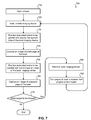
- FIG. 7 illustrates an embodiment of a method for capturing images of pages of a book using a book imaging device.
- a book In order to prevent a book from being damaged when opened, rather than opening the book to a wide angle, such as 180°, it may be opened to a smaller angle, such as 90° or 45°. The smaller the angle the book is opened to, the less likely any damage may occur to the book or the bookbinding.
- While opening a book to an angle less than 180° may decrease the likelihood that the book will be damaged, it may also make it difficult or impossible to view all of the information printed on the pages. For example, to view information printed in a book near the book's gutter, the book may need to be opened wide.
- a book imaging device may be used.
- Such a book imaging device may include two transparent plates, possibly made of glass or transparent plastic, offset from each other at approximately a 45° angle. Between these transparent plates, a dual sided mirror may be present. This dual sided mirror may be pivoted such that it is approximately parallel to each of the transparent plates.
- the book imaging device may facilitate the viewing of information printed on those pages of the book.
- the book imaging device may be inserted between two pages that are desired to be viewed. Inserting the book imaging device may create (or increase) a space between the two pages. This space may facilitate the viewing of information printed on pages of the book near the book's gutter. Further, the book imaging device may force some or all of the pages of the book into a position approximately parallel with either the first transparent plate or the second transparent plate, thereby reducing the curvature of the pages. Reducing the curvature of the pages being viewed may facilitate the imaging of these pages.
- the dual sided mirror may be positioned parallel with the transparent plate on the right of the book imaging device.
- An image of the first page may be transmitted through the first transparent plate, reflected by the dual sided mirror, and viewed by a person or imaged by an imaging device. Distortion of the first page may be minimized by the book viewing device having a 45° angle between the first transparent plate and the second transparent plate. This 45° angle may result in the image reflected by the dual mirror having little, if any, distortion when received by the imaging device or viewed by the person.
- the dual sided mirror may be positioned parallel to the transparent plate on the left of the book imaging device.
- An image of the second page may be transmitted through the second transparent plate, reflected by the dual sided mirror, and either viewed by the person or imaged by the same imaging device or a different imaging device.
- the book imaging device may be removed, the page of the book may be turned, and then the book imaging device may be reinserted to repeat the process for additional pages of the book.
- FIG. 2 illustrates an embodiment 200 of a book held open at a 45° angle.
- Book 210 contains a number of pages 220 .
- Book 210 also has a front cover 230 , a back cover 240 , and a bookbinding 250 .
- Book 210 is supported by a reprographic copy stand 260 .
- Reprographic copy stand 260 is configured to hold book 210 open at a 45° angle, as illustrated by dotted arrow 270 . It should be understood that the same or a different reprographic copy stands may be used to support book 210 at other angles.
- book 210 While book 210 is being supported by reprographic copy stand 260 , it may be difficult or impossible to view information printed near the gutter 280 of book 210 .
- a book imaging device may be used.
- FIG. 3 illustrates an embodiment 300 of a book held open at a 45° angle with a book imaging device about to be inserted.
- Book 210 of FIG. 3 may represent book 210 of FIG. 2 .
- reprographic copy stand 260 of FIG. 3 may represent reprographic copy stand 260 of FIG. 2 .
- Book imaging device 310 may include several parts: a first transparent plate 320 , a second transparent plate 330 , and a dual sided mirror 340 .
- First transparent plate 320 may be a flat panel of a transparent or semi-transparent material, such as glass or plastic.
- second transparent plate 330 may also be a flat-panel of a transparent, or semi-transparent material, such as glass or plastic.
- First transparent plate 320 and second transparent plate 330 may be connected at, roughly, a 45° angle, as represented by dotted arrow 350 .
- dual sided mirror 340 may be held in place, at least in part, by gravity.
- dual sided mirror 340 is attached with first transparent panel 320 and second transparent panel 330 by a hinge. This hinge may be located at or near where first transparent panel 320 and second transparent panel 330 meet.
- a space, or distance, between the pages that are open may be created or increased near gutter 280 . This increase in space or distance may make it easier (or possible) to view information printed on the open pages near gutter 280 . Also, inserting book imaging device 310 may provide support to pages 220 and either reduce or eliminate curvature 225 present in pages 220 .
- FIG. 4 illustrates an embodiment 400 of a book held open at a 45° angle with a book imaging device inserted between pages in the book.
- Book imaging device 310 of FIG. 4 may represent book imaging device 310 of FIG. 3 .
- book 210 of FIG. 4 may represent book 210 of FIGS. 2 and 3 .
- book imaging device 310 has been inserted between two pages of book 210 , such that the portion of book imaging device 310 where the first and second transparent panels meet is touching, or near, the binding of book 210 .
- book imaging device 310 may be referred to as having been inserted between a first page and a second page of book 210 . References to “a first page” and “a second page” do not refer to the page numbers; rather, these references refer to two different pages of the book.
- Image capture devices 470 and 480 may be present to capture images of the pages of book 210 .
- Image capture devices 470 and 480 may be cameras, video cameras, or some other devices capable of capturing images of open pages of book 210 .
- one image capture device may be used. If one image capture device is used, it may be necessary to reposition the image capturing device depending on whether a page on the left or right side of the book is being imaged.
- two image capture devices may be used. If two image capture devices are used, such as image capture devices 470 and 480 , one image capture device may be positioned to capture images of the page on the left of the book and one image capture device may be positioned to capture images of pages on the right of the book.
- image capture device 470 is positioned to capture images of pages on the right side of the book and image capture device 480 is positioned to capture images of pages on the left side of the book.
- Image capture devices 470 and 480 or a system connected with image capture devices 470 and 480 , such as a computer system, may be configured to invert images received using book imaging device 310 . This may be necessary because dual sided mirror 340 may invert the images, therefore, the images may need to be again inverted for the information printed on pages 210 to appear as printed.
- inserting book imaging device 310 may reduce the curvature in pages 210 . This reduction in curvature may allow for a sharper image, with less distortion, to be captured by image capture devices 470 and 480 . If text present on the pages is to be converted to machine encoded text, having a sharper image and a decreased amount of distortion may increase the likelihood that the conversion to machine encoded text accurately represents the text as printed on the pages.
- inserting book imaging device 310 into a book may increase a space between the pages being imaged. This increased space, or distance, between the pages that are open may be created or increased near gutter 280 . This increase in space or distance may make it easier or possible to view information printed on the open pages near gutter 280 .
- the image may be transmitted through transparent plate 330 and reflected by dual-sided mirror 340 .
- the image may be received by image capture device 480 .
- the image may be reflected by dual sided mirror 340 at a 90° angle from the second page to image capture device 480 .
- Tabs 630 and 640 may be present to help a user insert and/or remove book imaging device 310 from a book. Further, tabs 630 and 640 may help a user in not getting marks, such as fingerprints, on first transparent plate 320 and second transparent plate 330 by reducing the likelihood that a user would need to directly touch these components.
- Tab 650 may be attached with dual sided mirror 340 . Tab 650 may be present to help a user position dual sided mirror 340 from being parallel with first transparent plate 320 to being parallel with second transparent plate 330 , and from being parallel with second transparent plate 330 to being parallel with first transparent plate 320 .
- tab 640 may help a user in not getting marks, such as fingerprints, on first transparent plate 320 , second transparent plate 330 , or dual sided mirror 340 by reducing the likelihood that a user would need to directly touch these components of book imaging device 310 .
- a book imaging device such as book imaging device 310 , of FIGS. 3-6 , may be inserted between two pages of the book that are desired to be imaged. If both pages are not desired to be imaged, the book imaging device may be inserted next to the one page that is desired to be imaged. The book imaging device may be pressed firmly into place such that the lowest portion of the first transparent plate and the second transparent plate of the book imaging device is resting against or near the inside of the book's binding. Inserting the book imaging device between the two pages may create or increase the distance or space between the two pages near the book's gutter. This increase in space may facilitate an image being captured of each page of the book that includes all of the text present on each page. Further, inserting the book imaging device may provide support to the pages of the book such that curvature present in the pages being imaged is reduced or eliminated.
- one image capture device may be positioned to capture images of pages on the right side of the book, while the other image capture device may be positioned to capture images of pages on the left side of the book.
- the image capture devices may be positioned as image capture device 470 and image capture device 480 are positioned in FIG. 4 .
- the method may end. However, if more pages of the book are to be imaged, the method may continue to block 780 .
- a user may remove the book imaging device from the book.
- pages of the book may be turned to expose the next page or pages, of the book to be imaged. Once the next page or pages to be imaged are exposed, the method may return to block 720 .
- Method 700 may continue until all the pages of the book that are desired to be imaged have been imaged.
- the embodiments may be described as a process which is depicted as a flow diagram or block diagram. Although each may describe the operations as a sequential process, many of the operations can be performed in parallel or concurrently. In addition, the order of the operations may be rearranged. A process may have additional steps not included in the figure.
Landscapes
- Physics & Mathematics (AREA)
- General Physics & Mathematics (AREA)
- Optics & Photonics (AREA)
- Facsimile Scanning Arrangements (AREA)
- Studio Devices (AREA)
Abstract
Description
Claims (16)
Priority Applications (1)
| Application Number | Priority Date | Filing Date | Title |
|---|---|---|---|
| US13/022,813 US8801201B2 (en) | 2011-02-08 | 2011-02-08 | Dual sided mirror book imaging devices and methods |
Applications Claiming Priority (1)
| Application Number | Priority Date | Filing Date | Title |
|---|---|---|---|
| US13/022,813 US8801201B2 (en) | 2011-02-08 | 2011-02-08 | Dual sided mirror book imaging devices and methods |
Publications (2)
| Publication Number | Publication Date |
|---|---|
| US20120200948A1 US20120200948A1 (en) | 2012-08-09 |
| US8801201B2 true US8801201B2 (en) | 2014-08-12 |
Family
ID=46600495
Family Applications (1)
| Application Number | Title | Priority Date | Filing Date |
|---|---|---|---|
| US13/022,813 Active 2032-08-08 US8801201B2 (en) | 2011-02-08 | 2011-02-08 | Dual sided mirror book imaging devices and methods |
Country Status (1)
| Country | Link |
|---|---|
| US (1) | US8801201B2 (en) |
Citations (9)
| Publication number | Priority date | Publication date | Assignee | Title |
|---|---|---|---|---|
| US1346017A (en) * | 1920-07-06 | Milton goodman | ||
| JPS5989072A (en) * | 1982-11-12 | 1984-05-23 | Fuji Xerox Co Ltd | Reading device |
| GB2131969A (en) * | 1982-11-25 | 1984-06-27 | Charles Douglas Wehner | Stereoscopic viewers |
| DE3546404A1 (en) * | 1985-12-31 | 1987-07-02 | Pfreimter Hubert | Device for producing double sided reproductions from books |
| US5359207A (en) * | 1993-11-29 | 1994-10-25 | Xerox Corporation | Wedge scanner utilizing two dimensional sensing arrays |
| US5636006A (en) * | 1996-04-17 | 1997-06-03 | Xerox Corporation | Apparatus and method for scanning a bound document using a wedge shaped platen with a moving mirror |
| US5847846A (en) * | 1996-04-17 | 1998-12-08 | Xerox Corporation | Apparatus and method for scanning a bound color document using a wedge shaped platen |
| US6862074B2 (en) * | 2002-01-14 | 2005-03-01 | Oleg B. Tretiakoff | Portable device for the photographing of book pages |
| US7605844B1 (en) * | 2003-11-13 | 2009-10-20 | Google Inc. | Imaging opposing bound pages at high speed using multiple cameras |
-
2011
- 2011-02-08 US US13/022,813 patent/US8801201B2/en active Active
Patent Citations (9)
| Publication number | Priority date | Publication date | Assignee | Title |
|---|---|---|---|---|
| US1346017A (en) * | 1920-07-06 | Milton goodman | ||
| JPS5989072A (en) * | 1982-11-12 | 1984-05-23 | Fuji Xerox Co Ltd | Reading device |
| GB2131969A (en) * | 1982-11-25 | 1984-06-27 | Charles Douglas Wehner | Stereoscopic viewers |
| DE3546404A1 (en) * | 1985-12-31 | 1987-07-02 | Pfreimter Hubert | Device for producing double sided reproductions from books |
| US5359207A (en) * | 1993-11-29 | 1994-10-25 | Xerox Corporation | Wedge scanner utilizing two dimensional sensing arrays |
| US5636006A (en) * | 1996-04-17 | 1997-06-03 | Xerox Corporation | Apparatus and method for scanning a bound document using a wedge shaped platen with a moving mirror |
| US5847846A (en) * | 1996-04-17 | 1998-12-08 | Xerox Corporation | Apparatus and method for scanning a bound color document using a wedge shaped platen |
| US6862074B2 (en) * | 2002-01-14 | 2005-03-01 | Oleg B. Tretiakoff | Portable device for the photographing of book pages |
| US7605844B1 (en) * | 2003-11-13 | 2009-10-20 | Google Inc. | Imaging opposing bound pages at high speed using multiple cameras |
Also Published As
| Publication number | Publication date |
|---|---|
| US20120200948A1 (en) | 2012-08-09 |
Similar Documents
| Publication | Publication Date | Title |
|---|---|---|
| US8531740B1 (en) | Universal scanning stand for devices equipped with a digital camera | |
| CA2797269C (en) | Image capture | |
| US7911532B2 (en) | Notebook computer and method of capturing document image using image pickup device of such notebook computer | |
| JP4870815B2 (en) | Apparatus for easily photographing while observing an invisible image existing on a subject, and method of using the same | |
| US20080151099A1 (en) | Portable electronic device | |
| CN103873731B (en) | Information read device and information-reading method | |
| US20190205634A1 (en) | Capturing Digital Images of Documents | |
| WO2008137094A2 (en) | Slot in housing adapted to receive at least a portion of a printed paper item for optical character recognition | |
| US8801201B2 (en) | Dual sided mirror book imaging devices and methods | |
| CN201319110Y (en) | Folding image pickup device with scanning function | |
| US7970277B1 (en) | Business card case mountable on notebook computer | |
| CN215379051U (en) | an electronic device | |
| CN209879118U (en) | A sliding reflector structure and its electronic equipment | |
| WO2018010299A1 (en) | Auxiliary scanning tool capable of automatically adapting to books and files | |
| US8894027B2 (en) | Multi-angle and multi-position reprographic copy stand | |
| TW201039713A (en) | Notebook computer with document holding function | |
| CN205792869U (en) | Automatically adapt to the scanning auxiliary mould of books archives | |
| JP2012222654A (en) | Camera for paintings and writings | |
| CN101887290B (en) | Notebook computer with file clamping function | |
| CN206023910U (en) | A kind of portable multi-function data collection device | |
| US20080122970A1 (en) | Image capture device | |
| CN100466680C (en) | Scanning unit with double slope | |
| CN101662561B (en) | Method for extracting document image by pick-up device | |
| CN102298697A (en) | card information acquisition device | |
| KR100284162B1 (en) | Digital Image Pickup System |
Legal Events
| Date | Code | Title | Description |
|---|---|---|---|
| AS | Assignment |
Owner name: ANCESTRY.COM OPERATIONS INC., UTAH Free format text: ASSIGNMENT OF ASSIGNORS INTEREST;ASSIGNORS:REESE, JACK;REID, SHAWN;REEL/FRAME:025912/0511 Effective date: 20110228 |
|
| AS | Assignment |
Owner name: BARCLAYS BANK PLC, COLLATERAL AGENT, NEW YORK Free format text: PATENT SECURITY AGREEMENT;ASSIGNORS:ANCESTRY.COM OPERATIONS INC.;ANCESTRY.COM DNA, LLC;IARCHIVES, INC.;REEL/FRAME:029537/0064 Effective date: 20121228 |
|
| STCF | Information on status: patent grant |
Free format text: PATENTED CASE |
|
| AS | Assignment |
Owner name: ANCESTRY.COM DNA, LLC, UTAH Free format text: RELEASE (REEL 029537/ FRAME 0064);ASSIGNOR:BARCLAYS BANK PLC;REEL/FRAME:036514/0816 Effective date: 20150828 Owner name: ANCESTRY.COM OPERATIONS INC., UTAH Free format text: RELEASE (REEL 029537/ FRAME 0064);ASSIGNOR:BARCLAYS BANK PLC;REEL/FRAME:036514/0816 Effective date: 20150828 Owner name: IARCHIVES, INC., UTAH Free format text: RELEASE (REEL 029537/ FRAME 0064);ASSIGNOR:BARCLAYS BANK PLC;REEL/FRAME:036514/0816 Effective date: 20150828 |
|
| AS | Assignment |
Owner name: MORGAN STANLEY SENIOR FUNDING, INC., AS COLLATERAL Free format text: SECURITY AGREEMENT;ASSIGNORS:ANCESTRY.COM OPERATIONS INC.;IARCHIVES, INC.;ANCESTRY.COM DNA, LLC;REEL/FRAME:036519/0853 Effective date: 20150828 |
|
| AS | Assignment |
Owner name: ANCESTRY.COM DNA, LLC, UTAH Free format text: RELEASE BY SECURED PARTY;ASSIGNOR:MORGAN STANLEY SENIOR FUNDING, INC.;REEL/FRAME:040424/0354 Effective date: 20161019 Owner name: ANCESTRY.COM OPERATIONS INC., UTAH Free format text: RELEASE BY SECURED PARTY;ASSIGNOR:MORGAN STANLEY SENIOR FUNDING, INC.;REEL/FRAME:040424/0354 Effective date: 20161019 Owner name: IARCHIVES, INC., UTAH Free format text: RELEASE BY SECURED PARTY;ASSIGNOR:MORGAN STANLEY SENIOR FUNDING, INC.;REEL/FRAME:040424/0354 Effective date: 20161019 |
|
| AS | Assignment |
Owner name: JPMORGAN CHASE BANK, N.A., AS COLLATERAL AGENT, ILLINOIS Free format text: FIRST LIEN SECURITY AGREEMENT;ASSIGNORS:ANCESTRY.COM OPERATIONS INC.;IARCHIVES, INC.;ANCESTRY.COM DNA, LLC;AND OTHERS;REEL/FRAME:040449/0663 Effective date: 20161019 Owner name: JPMORGAN CHASE BANK, N.A., AS COLLATERAL AGENT, IL Free format text: FIRST LIEN SECURITY AGREEMENT;ASSIGNORS:ANCESTRY.COM OPERATIONS INC.;IARCHIVES, INC.;ANCESTRY.COM DNA, LLC;AND OTHERS;REEL/FRAME:040449/0663 Effective date: 20161019 |
|
| AS | Assignment |
Owner name: DEUTSCHE BANK AG NEW YORK BRANCH, AS COLLATERAL AGENT, NEW YORK Free format text: SECOND LIEN SECURITY AGREEMENT;ASSIGNORS:ANCESTRY.COM OPERATIONS INC.;IARCHIVES, INC.;ANCESTRY.COM DNA, LLC;AND OTHERS;REEL/FRAME:040259/0978 Effective date: 20161019 Owner name: DEUTSCHE BANK AG NEW YORK BRANCH, AS COLLATERAL AG Free format text: SECOND LIEN SECURITY AGREEMENT;ASSIGNORS:ANCESTRY.COM OPERATIONS INC.;IARCHIVES, INC.;ANCESTRY.COM DNA, LLC;AND OTHERS;REEL/FRAME:040259/0978 Effective date: 20161019 |
|
| AS | Assignment |
Owner name: ANCESTRY US HOLDINGS INC., UTAH Free format text: RELEASE BY SECURED PARTY;ASSIGNOR:DEUTSCHE BANK AG NEW YORK BRANCH;REEL/FRAME:044529/0025 Effective date: 20171128 Owner name: ANCESTRY.COM OPERATIONS INC., UTAH Free format text: RELEASE BY SECURED PARTY;ASSIGNOR:DEUTSCHE BANK AG NEW YORK BRANCH;REEL/FRAME:044529/0025 Effective date: 20171128 Owner name: ANCESTRY.COM INC., UTAH Free format text: RELEASE BY SECURED PARTY;ASSIGNOR:DEUTSCHE BANK AG NEW YORK BRANCH;REEL/FRAME:044529/0025 Effective date: 20171128 Owner name: ANCESTRY.COM LLC, UTAH Free format text: RELEASE BY SECURED PARTY;ASSIGNOR:DEUTSCHE BANK AG NEW YORK BRANCH;REEL/FRAME:044529/0025 Effective date: 20171128 |
|
| MAFP | Maintenance fee payment |
Free format text: PAYMENT OF MAINTENANCE FEE, 4TH YEAR, LARGE ENTITY (ORIGINAL EVENT CODE: M1551) Year of fee payment: 4 |
|
| AS | Assignment |
Owner name: ANCESTRYHEALTH.COM, LLC, UTAH Free format text: RELEASE OF FIRST LIEN SECURITY INTEREST;ASSIGNOR:JPMORGAN CHASE BANK, N.A.;REEL/FRAME:054618/0298 Effective date: 20201204 Owner name: ANCESTRY.COM DNA, LLC, UTAH Free format text: RELEASE OF FIRST LIEN SECURITY INTEREST;ASSIGNOR:JPMORGAN CHASE BANK, N.A.;REEL/FRAME:054618/0298 Effective date: 20201204 Owner name: IARCHIVES, INC., UTAH Free format text: RELEASE OF FIRST LIEN SECURITY INTEREST;ASSIGNOR:JPMORGAN CHASE BANK, N.A.;REEL/FRAME:054618/0298 Effective date: 20201204 Owner name: ADPAY, INC., UTAH Free format text: RELEASE OF FIRST LIEN SECURITY INTEREST;ASSIGNOR:JPMORGAN CHASE BANK, N.A.;REEL/FRAME:054618/0298 Effective date: 20201204 Owner name: ANCESTRY.COM OPERATIONS INC., UTAH Free format text: RELEASE OF FIRST LIEN SECURITY INTEREST;ASSIGNOR:JPMORGAN CHASE BANK, N.A.;REEL/FRAME:054618/0298 Effective date: 20201204 Owner name: WILMINGTON TRUST, NATIONAL ASSOCIATION, CONNECTICUT Free format text: SECURITY INTEREST;ASSIGNORS:ANCESTRY.COM DNA, LLC;ANCESTRY.COM OPERATIONS INC.;IARCHIVES, INC.;AND OTHERS;REEL/FRAME:054627/0237 Effective date: 20201204 Owner name: CREDIT SUISSE AG, CAYMAN ISLANDS BRANCH, NEW YORK Free format text: SECURITY INTEREST;ASSIGNORS:ANCESTRY.COM DNA, LLC;ANCESTRY.COM OPERATIONS INC.;IARCHIVES, INC.;AND OTHERS;REEL/FRAME:054627/0212 Effective date: 20201204 |
|
| MAFP | Maintenance fee payment |
Free format text: PAYMENT OF MAINTENANCE FEE, 8TH YEAR, LARGE ENTITY (ORIGINAL EVENT CODE: M1552); ENTITY STATUS OF PATENT OWNER: LARGE ENTITY Year of fee payment: 8 |