US8800709B2 - Apparatus for determining vehicle rollover risk - Google Patents
Apparatus for determining vehicle rollover risk Download PDFInfo
- Publication number
- US8800709B2 US8800709B2 US13/241,655 US201113241655A US8800709B2 US 8800709 B2 US8800709 B2 US 8800709B2 US 201113241655 A US201113241655 A US 201113241655A US 8800709 B2 US8800709 B2 US 8800709B2
- Authority
- US
- United States
- Prior art keywords
- rollover
- vehicle
- tendency
- resultant
- acceleration
- Prior art date
- Legal status (The legal status is an assumption and is not a legal conclusion. Google has not performed a legal analysis and makes no representation as to the accuracy of the status listed.)
- Active, expires
Links
- 230000001133 acceleration Effects 0.000 claims abstract description 489
- 230000036461 convulsion Effects 0.000 claims abstract description 136
- 230000008859 change Effects 0.000 claims abstract description 36
- 230000015572 biosynthetic process Effects 0.000 claims abstract description 17
- 238000003786 synthesis reaction Methods 0.000 claims abstract description 17
- 230000033001 locomotion Effects 0.000 claims description 101
- 239000007788 liquid Substances 0.000 description 29
- 230000003247 decreasing effect Effects 0.000 description 19
- 230000001052 transient effect Effects 0.000 description 17
- 238000000034 method Methods 0.000 description 11
- 238000012545 processing Methods 0.000 description 8
- 238000001514 detection method Methods 0.000 description 7
- 238000010586 diagram Methods 0.000 description 7
- 230000003068 static effect Effects 0.000 description 7
- 230000001629 suppression Effects 0.000 description 7
- 230000000694 effects Effects 0.000 description 6
- 230000009471 action Effects 0.000 description 5
- 230000000052 comparative effect Effects 0.000 description 5
- 230000006870 function Effects 0.000 description 4
- 238000005096 rolling process Methods 0.000 description 4
- 238000013459 approach Methods 0.000 description 3
- 230000005540 biological transmission Effects 0.000 description 3
- 230000008901 benefit Effects 0.000 description 2
- 238000004891 communication Methods 0.000 description 2
- 230000004069 differentiation Effects 0.000 description 2
- 239000000284 extract Substances 0.000 description 2
- 238000001914 filtration Methods 0.000 description 2
- 230000010354 integration Effects 0.000 description 2
- 238000012986 modification Methods 0.000 description 2
- 230000004048 modification Effects 0.000 description 2
- 238000012544 monitoring process Methods 0.000 description 2
- 230000007935 neutral effect Effects 0.000 description 2
- 230000009467 reduction Effects 0.000 description 2
- 230000004044 response Effects 0.000 description 2
- 230000009466 transformation Effects 0.000 description 2
- 101001103039 Homo sapiens Inactive tyrosine-protein kinase transmembrane receptor ROR1 Proteins 0.000 description 1
- 101001103036 Homo sapiens Nuclear receptor ROR-alpha Proteins 0.000 description 1
- 102100039614 Nuclear receptor ROR-alpha Human genes 0.000 description 1
- 230000003044 adaptive effect Effects 0.000 description 1
- 238000002485 combustion reaction Methods 0.000 description 1
- 239000002131 composite material Substances 0.000 description 1
- 238000013461 design Methods 0.000 description 1
- 238000002474 experimental method Methods 0.000 description 1
- 230000006872 improvement Effects 0.000 description 1
- 230000035945 sensitivity Effects 0.000 description 1
- 230000002194 synthesizing effect Effects 0.000 description 1
Images


Classifications
-
- B—PERFORMING OPERATIONS; TRANSPORTING
- B60—VEHICLES IN GENERAL
- B60R—VEHICLES, VEHICLE FITTINGS, OR VEHICLE PARTS, NOT OTHERWISE PROVIDED FOR
- B60R21/00—Arrangements or fittings on vehicles for protecting or preventing injuries to occupants or pedestrians in case of accidents or other traffic risks
- B60R21/01—Electrical circuits for triggering passive safety arrangements, e.g. airbags, safety belt tighteners, in case of vehicle accidents or impending vehicle accidents
- B60R21/013—Electrical circuits for triggering passive safety arrangements, e.g. airbags, safety belt tighteners, in case of vehicle accidents or impending vehicle accidents including means for detecting collisions, impending collisions or roll-over
- B60R21/0132—Electrical circuits for triggering passive safety arrangements, e.g. airbags, safety belt tighteners, in case of vehicle accidents or impending vehicle accidents including means for detecting collisions, impending collisions or roll-over responsive to vehicle motion parameters, e.g. to vehicle longitudinal or transversal deceleration or speed value
-
- B—PERFORMING OPERATIONS; TRANSPORTING
- B60—VEHICLES IN GENERAL
- B60T—VEHICLE BRAKE CONTROL SYSTEMS OR PARTS THEREOF; BRAKE CONTROL SYSTEMS OR PARTS THEREOF, IN GENERAL; ARRANGEMENT OF BRAKING ELEMENTS ON VEHICLES IN GENERAL; PORTABLE DEVICES FOR PREVENTING UNWANTED MOVEMENT OF VEHICLES; VEHICLE MODIFICATIONS TO FACILITATE COOLING OF BRAKES
- B60T8/00—Arrangements for adjusting wheel-braking force to meet varying vehicular or ground-surface conditions, e.g. limiting or varying distribution of braking force
- B60T8/17—Using electrical or electronic regulation means to control braking
- B60T8/1755—Brake regulation specially adapted to control the stability of the vehicle, e.g. taking into account yaw rate or transverse acceleration in a curve
- B60T8/17551—Brake regulation specially adapted to control the stability of the vehicle, e.g. taking into account yaw rate or transverse acceleration in a curve determining control parameters related to vehicle stability used in the regulation, e.g. by calculations involving measured or detected parameters
-
- B—PERFORMING OPERATIONS; TRANSPORTING
- B60—VEHICLES IN GENERAL
- B60T—VEHICLE BRAKE CONTROL SYSTEMS OR PARTS THEREOF; BRAKE CONTROL SYSTEMS OR PARTS THEREOF, IN GENERAL; ARRANGEMENT OF BRAKING ELEMENTS ON VEHICLES IN GENERAL; PORTABLE DEVICES FOR PREVENTING UNWANTED MOVEMENT OF VEHICLES; VEHICLE MODIFICATIONS TO FACILITATE COOLING OF BRAKES
- B60T8/00—Arrangements for adjusting wheel-braking force to meet varying vehicular or ground-surface conditions, e.g. limiting or varying distribution of braking force
- B60T8/17—Using electrical or electronic regulation means to control braking
- B60T8/1755—Brake regulation specially adapted to control the stability of the vehicle, e.g. taking into account yaw rate or transverse acceleration in a curve
- B60T8/17554—Brake regulation specially adapted to control the stability of the vehicle, e.g. taking into account yaw rate or transverse acceleration in a curve specially adapted for enhancing stability around the vehicles longitudinal axle, i.e. roll-over prevention
-
- B—PERFORMING OPERATIONS; TRANSPORTING
- B60—VEHICLES IN GENERAL
- B60W—CONJOINT CONTROL OF VEHICLE SUB-UNITS OF DIFFERENT TYPE OR DIFFERENT FUNCTION; CONTROL SYSTEMS SPECIALLY ADAPTED FOR HYBRID VEHICLES; ROAD VEHICLE DRIVE CONTROL SYSTEMS FOR PURPOSES NOT RELATED TO THE CONTROL OF A PARTICULAR SUB-UNIT
- B60W30/00—Purposes of road vehicle drive control systems not related to the control of a particular sub-unit, e.g. of systems using conjoint control of vehicle sub-units
- B60W30/02—Control of vehicle driving stability
- B60W30/04—Control of vehicle driving stability related to roll-over prevention
-
- B—PERFORMING OPERATIONS; TRANSPORTING
- B60—VEHICLES IN GENERAL
- B60R—VEHICLES, VEHICLE FITTINGS, OR VEHICLE PARTS, NOT OTHERWISE PROVIDED FOR
- B60R21/00—Arrangements or fittings on vehicles for protecting or preventing injuries to occupants or pedestrians in case of accidents or other traffic risks
- B60R21/01—Electrical circuits for triggering passive safety arrangements, e.g. airbags, safety belt tighteners, in case of vehicle accidents or impending vehicle accidents
- B60R2021/01204—Actuation parameters of safety arrangents
- B60R2021/01252—Devices other than bags
- B60R2021/01259—Brakes
-
- B—PERFORMING OPERATIONS; TRANSPORTING
- B60—VEHICLES IN GENERAL
- B60R—VEHICLES, VEHICLE FITTINGS, OR VEHICLE PARTS, NOT OTHERWISE PROVIDED FOR
- B60R21/00—Arrangements or fittings on vehicles for protecting or preventing injuries to occupants or pedestrians in case of accidents or other traffic risks
- B60R21/01—Electrical circuits for triggering passive safety arrangements, e.g. airbags, safety belt tighteners, in case of vehicle accidents or impending vehicle accidents
- B60R21/013—Electrical circuits for triggering passive safety arrangements, e.g. airbags, safety belt tighteners, in case of vehicle accidents or impending vehicle accidents including means for detecting collisions, impending collisions or roll-over
- B60R2021/01306—Electrical circuits for triggering passive safety arrangements, e.g. airbags, safety belt tighteners, in case of vehicle accidents or impending vehicle accidents including means for detecting collisions, impending collisions or roll-over monitoring vehicle inclination
-
- B—PERFORMING OPERATIONS; TRANSPORTING
- B60—VEHICLES IN GENERAL
- B60R—VEHICLES, VEHICLE FITTINGS, OR VEHICLE PARTS, NOT OTHERWISE PROVIDED FOR
- B60R21/00—Arrangements or fittings on vehicles for protecting or preventing injuries to occupants or pedestrians in case of accidents or other traffic risks
- B60R21/01—Electrical circuits for triggering passive safety arrangements, e.g. airbags, safety belt tighteners, in case of vehicle accidents or impending vehicle accidents
- B60R21/013—Electrical circuits for triggering passive safety arrangements, e.g. airbags, safety belt tighteners, in case of vehicle accidents or impending vehicle accidents including means for detecting collisions, impending collisions or roll-over
- B60R21/0132—Electrical circuits for triggering passive safety arrangements, e.g. airbags, safety belt tighteners, in case of vehicle accidents or impending vehicle accidents including means for detecting collisions, impending collisions or roll-over responsive to vehicle motion parameters, e.g. to vehicle longitudinal or transversal deceleration or speed value
- B60R2021/01327—Angular velocity or angular acceleration
-
- B—PERFORMING OPERATIONS; TRANSPORTING
- B60—VEHICLES IN GENERAL
- B60T—VEHICLE BRAKE CONTROL SYSTEMS OR PARTS THEREOF; BRAKE CONTROL SYSTEMS OR PARTS THEREOF, IN GENERAL; ARRANGEMENT OF BRAKING ELEMENTS ON VEHICLES IN GENERAL; PORTABLE DEVICES FOR PREVENTING UNWANTED MOVEMENT OF VEHICLES; VEHICLE MODIFICATIONS TO FACILITATE COOLING OF BRAKES
- B60T2230/00—Monitoring, detecting special vehicle behaviour; Counteracting thereof
- B60T2230/03—Overturn, rollover
-
- B—PERFORMING OPERATIONS; TRANSPORTING
- B60—VEHICLES IN GENERAL
- B60T—VEHICLE BRAKE CONTROL SYSTEMS OR PARTS THEREOF; BRAKE CONTROL SYSTEMS OR PARTS THEREOF, IN GENERAL; ARRANGEMENT OF BRAKING ELEMENTS ON VEHICLES IN GENERAL; PORTABLE DEVICES FOR PREVENTING UNWANTED MOVEMENT OF VEHICLES; VEHICLE MODIFICATIONS TO FACILITATE COOLING OF BRAKES
- B60T2240/00—Monitoring, detecting wheel/tyre behaviour; counteracting thereof
- B60T2240/06—Wheel load; Wheel lift
-
- B—PERFORMING OPERATIONS; TRANSPORTING
- B60—VEHICLES IN GENERAL
- B60W—CONJOINT CONTROL OF VEHICLE SUB-UNITS OF DIFFERENT TYPE OR DIFFERENT FUNCTION; CONTROL SYSTEMS SPECIALLY ADAPTED FOR HYBRID VEHICLES; ROAD VEHICLE DRIVE CONTROL SYSTEMS FOR PURPOSES NOT RELATED TO THE CONTROL OF A PARTICULAR SUB-UNIT
- B60W30/00—Purposes of road vehicle drive control systems not related to the control of a particular sub-unit, e.g. of systems using conjoint control of vehicle sub-units
- B60W30/02—Control of vehicle driving stability
- B60W30/04—Control of vehicle driving stability related to roll-over prevention
- B60W2030/041—Control of vehicle driving stability related to roll-over prevention about the pitch axis
-
- B—PERFORMING OPERATIONS; TRANSPORTING
- B60—VEHICLES IN GENERAL
- B60W—CONJOINT CONTROL OF VEHICLE SUB-UNITS OF DIFFERENT TYPE OR DIFFERENT FUNCTION; CONTROL SYSTEMS SPECIALLY ADAPTED FOR HYBRID VEHICLES; ROAD VEHICLE DRIVE CONTROL SYSTEMS FOR PURPOSES NOT RELATED TO THE CONTROL OF A PARTICULAR SUB-UNIT
- B60W30/00—Purposes of road vehicle drive control systems not related to the control of a particular sub-unit, e.g. of systems using conjoint control of vehicle sub-units
- B60W30/02—Control of vehicle driving stability
- B60W30/04—Control of vehicle driving stability related to roll-over prevention
- B60W2030/043—Control of vehicle driving stability related to roll-over prevention about the roll axis
Definitions
- the present invention relates to a control apparatus for a vehicle and, particularly, relates to an apparatus for determining a tendency of rollover of the vehicle.
- a Japanese PCT Application Publication (tokuhyou) No. 2004-534694 published on Nov. 18, 2004 (which corresponds to WO 03/008242 A1 published on Jan. 30, 2003 and corresponds to a U.S. Pat. No. 7,149,614 issued on Dec. 12, 2006) exemplifies a previously proposed vehicular control apparatus which determines the tendency of rollover of the vehicle.
- a variable representing a lateral dynamic characteristic of the vehicle is prepared using a lateral acceleration of the vehicle and the tendency of rollover of the vehicle is determined depending upon whether the value of the variable is equal to or larger than a threshold value.
- an object of the present invention to provide a control apparatus for a vehicle which is capable of improving the determination accuracy of the tendency of rollover of the vehicle.
- the apparatus according to the present invention particularly, the tendency of rollover of the vehicle is determined using a resultant acceleration which is a synthesis of accelerations in a plurality of directions of the vehicle acted upon the vehicle.
- a control apparatus for a vehicle comprising a control unit including: a resultant acceleration information calculating section configured to calculate a resultant acceleration which is a synthesis of two direction accelerations acted upon the vehicle; a resultant jerk calculating section configured to calculate a resultant jerk of at least one of change rates of the two direction accelerations with respect to time and a change rate of the resultant acceleration with respect to time; and a rollover tendency determining section configured to determine a tendency of rollover of the vehicle using at least one of the calculated resultant acceleration and the calculated resultant jerk.
- a control apparatus for a vehicle comprising: a longitudinal acceleration calculating section configured to calculate a longitudinal acceleration acted upon the vehicle; a lateral acceleration calculating section configured to calculate a lateral acceleration acted upon the vehicle; a resultant acceleration information calculating section configured to calculate a resultant acceleration information related to a resultant acceleration which is a synthesis of the calculated respective accelerations; a rollover tendency determining section configured to determine the tendency of rollover of the vehicle on a basis of a magnitude of the calculated resultant acceleration information; and a control unit configured to actuate a brake actuator to provide a braking force for at least one or each of road wheels installed on the vehicle when the rollover tendency determining section determines the tendency of rollover of the vehicle.
- a control apparatus for a vehicle comprising: a longitudinal acceleration sensor configured to detect a longitudinal acceleration acted upon the vehicle; a lateral acceleration sensor configured to detect a lateral acceleration acted upon the vehicle; a resultant acceleration calculating section configured to detect a resultant acceleration on a basis of the detected longitudinal acceleration and lateral acceleration; a resultant jerk calculating section configured to calculate a change rate of the calculated resultant acceleration with respect to time; and a control unit configured to calculate a motion of the vehicle on a basis of the calculated resultant acceleration and the resultant jerk and configured to determine a tendency of rollover of the vehicle when the calculated motion of the vehicle is larger than a predetermined motion.
- FIG. 1A is a system configuration view of a vehicle in which a control apparatus in a first preferred embodiment according to the present invention is applicable.
- FIG. 1B is a functional block diagram of a brake control unit (brake CU) 1 shown in FIG. 1A .
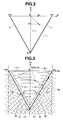
- FIG. 2 is a coordinate system view with a longitudinal axis taken as a longitudinal acceleration and with a lateral axis taken as a lateral acceleration and representing a definition of a rollover region ⁇ of the vehicle.
- FIG. 3 is a coordinate system view with the longitudinal axis taken as the longitudinal acceleration and with the lateral axis taken as the lateral acceleration and representing the definition of rollover region ⁇ of the vehicle and the definition of a rollover tendency region ⁇ of the vehicle.
- FIGS. 4A and 4B are explanatory view for explaining a method of application(s) of braking force(s) to respective road wheels or one of road wheels to suppress the rollover tendency of the vehicle, respectively.
- FIG. 5 is a calculation block diagram of a brake control section 200 shown in FIG. 1B to suppress the rollover tendency of the vehicle.
- FIG. 6 is a coordinate system view with the longitudinal axis taken as the longitudinal acceleration and with the lateral axis taken as the lateral acceleration and representing a locus of a resultant acceleration on the coordinate system.
- FIGS. 7A , 7 B, 7 C, and 7 D are integrally a timing chart representing time series of respective variables in an operation example shown in FIG. 6 .
- FIG. 8 is a characteristic graph representing a relationship between a slip rate of a road wheel and a force acted upon a tire of the road wheel.
- FIG. 9 is a coordinate system view with the longitudinal axis taken as the longitudinal acceleration and with the lateral axis taken as the lateral acceleration and representing a method for extracting a normal direction component of a resultant jerk.
- FIG. 10 is a coordinate system view with the lateral axis taken as a margin to a rollover boundary line and with the longitudinal axis taken as a normal direction component of a resultant jerk.
- FIG. 11 is a coordinate system view with the lateral axis taken as the margin to the rollover boundary line and with the longitudinal axis taken as the normal direction component of the resultant jerk and representing the locus of the operation example shown in FIG. 6 in the coordinate system.
- FIG. 12 is a calculation block diagram of a rollover tendency integrated value (a risk of rollover).
- FIGS. 13A and 13B are graphs representing time variations in the risk of rollover.
- FIG. 1A is a rough configuration view of a vehicular system on which the control apparatus is mounted.
- the vehicle is provided with a plurality of road wheels, specifically, four road wheels of front left road wheel FL, front right road wheel FR, a rear right road wheel RR, and a rear left road wheel RL.
- An output of an internal combustion engine (engine ENG) is transmitted to front road wheels FL, FR which are driving wheels as a driving force with a gear shift carried out through an automatic transmission AT.
- the driving system is provided with an accelerator opening angle sensor 16 which detects a depression quantity (of an accelerator pedal AP), namely, (a demanded driving force of a driver) and is provided with an engine control unit 7 and an AT (Automatic Transmission) control unit 8 which receive the information inputted from accelerator opening angle sensor 16 and a CAN (Controller Area Network) communication line (a CAN bus 9 ), outputs a command signal to engine ENG and automatic transmission AT to control the driving force of front road wheels FL, FR.
- a CAN Controller Area Network
- a brake system includes: a brake control unit (Brake CU) 1 , a brake pedal 2 ; a master cylinder 3 ; a liquid pressure unit (HU) 4 ; wheel cylinders 61 , 62 , 63 , 64 ; and various kinds of sensors.
- Brake pedal 2 is an operational member through which a driving operation by a vehicle driver is inputted and is connected to master cylinder 3 via a booster 2 a which is a servo unit (or a boosting unit).
- Master cylinder 3 is, so-called, a tandem type and is connected to liquid pressure unit (HU) 4 via two-system brake pipings 5 a , 5 b .
- Liquid pressure unit 4 is a hydraulic pressure unit having a hydraulic pressure circuit.
- Wheel cylinders 61 through 64 are connected to liquid pressure unit 4 via brake pipings 51 through 54 such that brake pressures (wheel cylinder pressure) can be generated on respective road wheels FL, FR, RL, RR.
- a brake circuit thereof is, so-called, an X piping structure in which wheel cylinders 61 , 64 for left front road wheel FL and right rear road wheel RR are connected to a P system brake piping 5 a and wheel cylinders 62 , 63 for right front road wheel FR and for left front road wheel FL are connected to an S system brake piping 5 b , respectively.
- the brake circuit may be, so-called, a longitudinal piping structure.
- Master cylinder 3 generates a liquid pressure (a master cylinder pressure) in accordance with a depression quantity (a manipulated variable) of brake pedal 2 upon receipt of the supply of a brake liquid from a reservoir tank 3 a integrally installed on master cylinder 3 .
- the master cylinder pressure is supplied to each wheel cylinder 61 through 64 via liquid pressure unit (HU) 4 .
- the liquid pressure of each wheel cylinder generates the driving force for the corresponding one of the road wheels FL, FR, RL, RR.
- Liquid pressure unit 4 is a brake actuator in which a plurality of electromagnetic valves, an electric motor 4 a , and pumps are disposed and wheel cylinder liquid pressures of respective road wheels FL, FR, RL, RR are arbitrarily increased or decreased through the controls of operations of electromagnetic valves so as to have a function such that a desired driving force can be given for each of the plurality of road wheels.
- Brake control unit (Brake CU) 1 is an electronic control unit (ECU) which performs a determination of a brake control execution on a basis of the information inputted from various sensors and CAN bus 9 and outputs a command signal to liquid pressure unit 4 to control an actuation of liquid pressure unit 4 to execute the brake control.
- ECU electronice control unit
- the brake control has a meaning that a wheel lock is suppressed or a vehicular motion is controlled by controlling the wheel cylinder liquid pressures (braking pressures) of respective road wheels FL, FR, RL, RR in response to requests of functions of securing a safety and convenience such as an anti lock brake control ABS (Anti Lock Brake System) which suppresses an increase in a wheel slip rate of the vehicle and a stability control VDC (Vehicle Dynamics Control) which suppresses a vehicular sideslip.
- ABS Anti Lock Brake System
- VDC Vehicle Dynamics Control
- brake control unit 1 may be disposed as an integral unit with liquid pressure unit 4 but may mutually separately be disposed.
- Brake control unit 1 , engine control unit 7 , and AT control unit 8 are mutually interconnected with CAN communication line (CAN bus 9 ) which is bi-directionally communicable and the information is communicable in both directions.
- CAN communication line CAN bus 9
- the various kinds of sensors constitute vehicular information detecting means and are provided with a vehicular motion sensor unit 10 ; road wheel speed sensors 11 through 14 ; and a steering angle sensor 15 .
- Road wheel speed sensors 11 through 14 are installed on respective road wheels FL, FR, RL, RR for detecting revolution speeds (road wheel speeds) of respectively corresponding road wheels FL, FR, RL, RR and for outputting detection signals thereon to brake control unit 1 .
- Steering angle sensor 15 detects a rotational angle (namely, a steering angle) of a steering wheel (SW) that the driver operates and outputs the detection signal to CAN bus 9 .
- Vehicular motion sensor unit 10 is a composite sensor integrated with sensors 17 , 18 , 19 which detect various information such as an acceleration G and a yaw rate ⁇ , each representing a vehicular motion, and outputs the detection signals to brake control unit 1 .
- a longitudinal acceleration sensor 17 detects an acceleration in a longitudinal direction acted upon the vehicle, namely, a longitudinal acceleration Xg representing a vehicular pitching motion.
- Lateral acceleration sensor 18 detects an acceleration in the longitudinal direction acted upon the vehicle, namely, a lateral acceleration Yg representing a roll motion of the vehicle.
- Yaw rate sensor 19 detects a change speed of the rotational angle in a turning direction of the vehicle, namely, a yaw rate ⁇ representing a yawing motion of the vehicle.
- Brake control unit 1 adjusts a brake pressure of each of road wheels FL, FR, RL, RR in accordance with the detected vehicular motion and the corresponding road wheel revolution speed.
- the brake controls such as ABS, VDC, and ACC (Adaptive Cruise Control) are executed. The details of these controls are well known. Hence, the explanation thereon will, herein, be omitted.
- Brake control unit 1 (hereinafter, also simply referred to as a control unit 1 ) constitutes the control apparatus for the vehicle.
- FIG. 1B shows a functional block diagram of control unit 1 shown in FIG. 1A .
- Control unit 1 in the first embodiment includes a vehicular motion determining section 100 and a brake control section 200 .
- Vehicular motion determining section 100 determines whether the vehicle has a tendency of rollover of the vehicle.
- rollover tendency represents a probability (a degree of possibility) of an occurrence of the rollover of the vehicle and means not only a presence or absence of the possibility of the rollover occurrence but also its height (high possibility or low possibility).
- brake control section 200 actuates liquid pressure unit 4 so that braking forces are given to the plurality of road wheels FL, FR, RL, RR to suppress the rollover tendency (refer to FIG. 4A ).
- Vehicular motion determining section 100 includes: a longitudinal acceleration calculating section 100 a which calculates an acceleration Xg in a longitudinal direction (a forward-and-backward direction of the vehicle) acted upon the vehicle; a lateral acceleration calculating section 100 b which calculates another acceleration Yg in a lateral direction (a leftward-and-rightward direction of the vehicle) acted upon the vehicle; a resultant acceleration information calculating section 100 c which calculates a resultant acceleration information related to a resultant acceleration G which is a synthesis of respectively calculated accelerations Xg, Yg; a rollover boundary line setting section 100 d which presets a rollover boundary line; and a rollover tendency determining section 100 e which determines the tendency of rollover of the vehicle using the calculated resultant acceleration information and the rollover boundary line.
- Longitudinal acceleration and lateral acceleration calculating sections 100 a , 100 b calculates the longitudinal acceleration Xg and lateral acceleration Yg respectively on a basis of the detection signals from vehicular motion sensor unit 10 . It should be noted that it is preferable to execute a filtering calculation for each of the detection signals of the sensors in order to extract acceleration components of the vehicular motion by eliminating external disturbance components of the accelerations due to road surface noises.
- Resultant acceleration calculating section 100 c 1 calculates a resultant acceleration G on a basis of longitudinal acceleration Xg and lateral acceleration Yg calculated respectively by longitudinal acceleration calculating section 100 a and lateral acceleration calculating section 100 b . It is possible to derive resultant acceleration G according to a resultant vector which is the synthesis of two directional accelerations Xg, Yg acted upon the vehicle.
- Rollover boundary line setting section 100 d sets rollover boundary line L.
- Rollover boundary line L serves to divide a region into a rollover region ⁇ in which there is a high possibility of the occurrence of rollover of the vehicle (an overturn of the vehicle in the lateral direction) when lateral acceleration Yg and longitudinal acceleration Xg are applied to the vehicle and a non-rollover region as another region than rollover region ⁇ , namely, a stable region ⁇ .
- rollover boundary line L which divides the region into rollover region ⁇ and stable region ⁇ is a boundary line related to acceleration (Xg, Yg).
- rollover boundary line L is set on a line connecting points at each of which a wheel load at a turning inner wheel side indicates zero (a resultant acceleration G) when both of lateral acceleration Yg and longitudinal acceleration Xg are applied to the vehicle.
- rollover boundary line L is set on a basis of specifications of the vehicle to which the control apparatus according to the present invention is applicable.
- the present invention is not limited to the setting method which will be described below but an appropriate setting method can be selected.
- a subscript f denotes front road wheels
- a subscript r denotes rear road wheels
- a subscript x denotes a vehicular longitudinal direction
- a subscript y denotes a vehicular lateral direction, respectively.
- steady-state front road wheel movement quantity ⁇ W ⁇ f and steady-state rear road wheel movement quantity ⁇ W ⁇ r are derived from equations (1) and (2) respectively, in a case where only the lateral acceleration is applied.
- m s denotes a vehicle weight
- a y denotes the lateral acceleration
- h s denotes a distance between a roll center at a vehicular weight center position and the vehicular weight center
- K ⁇ f denotes a front road wheel axle roll rigidity
- K ⁇ r denotes a rear road wheel axle roll rigidity
- g denotes a gravitational acceleration
- d f denotes a front road wheel tread
- d r denotes a rear road wheel tread
- l denotes a wheel base
- l f denotes a distance from the vehicle weight center to an axle of the front road wheels
- l r denotes a distance from the vehicular weight center position to an axle of rear road wheels
- a static wheel load is determined according to a relationship between the weight center and the vehicle weight center position.
- limit values a yf0 , a yr0 of lateral accelerations that front road wheel load decrease quantity ⁇ W ⁇ f and rear road wheel load decrease quantity ⁇ W ⁇ r exceed the corresponding static wheel load can be represented by numerical equations (numerical equations (3) and (4)), respectively, as steady-state characteristics. It should be noted that the lateral acceleration is acted upon leftward and rightward directions of the vehicle, a positive value or negative value is resulted.
- load decrease quantity ⁇ W ⁇ of one of limit values a yf0 , a yr0 , for front and rear road wheels whose absolute value is smaller than the other thereof exceeds the static wheel load at an earlier timing.
- the rear road wheels have started to become float from a road surface at the earlier timing than the front road wheels.
- a yf ⁇ ⁇ 0 ⁇ l r 2 ⁇ l ⁇ gd f ⁇ [ K ⁇ ⁇ ⁇ f ⁇ h s K ⁇ ⁇ ⁇ f + K ⁇ ⁇ ⁇ r - m s ⁇ gh s + l r l ⁇ h f ] - 1 ( Equation ⁇ ⁇ 3 )
- a y ⁇ ⁇ r ⁇ 0 ⁇ l f 2 ⁇ l ⁇ gd r ⁇ [ K ⁇ ⁇ ⁇ r ⁇ h s K ⁇ ⁇ ⁇ f + K ⁇ ⁇ ⁇ r - m s ⁇ gh s + l r l ⁇ h f ] - 1 ( Equation ⁇ ⁇ 4 )
- limit values a xf0 , a xr0 can simply be represented s
- Limit values a xf0 , a xr0 of longitudinal acceleration at which each of front road wheel load decrease quantity and rear road wheel decrease quantities ⁇ W ⁇ f , ⁇ W ⁇ r which exceed the static weight load can be represented by the following equations (5) and (6).
- a most simplest technique may be thought as a method in which the above-described respective points ⁇ a yo , a xf0 , a xf0 , a xr0 are connected with a straight line.
- a physical prerequisite of connecting these points with the straight line is the same as supposing that road wheel load movement quantity according to lateral acceleration a y and load movement quantity ⁇ W ⁇ according to longitudinal acceleration a x are represented by a sum (a linear combination).
- FIG. 2 shows a coordinate system with the longitudinal axis taken as longitudinal acceleration a x , the lateral axis taken as lateral acceleration a y , and a point at which both of longitudinal acceleration a x and lateral acceleration a y indicate zero taken as an origin 0 .
- FIG. 2 shows an example of defining rollover region ⁇ of the vehicle according to the method connecting the above-described four points ⁇ a y0 , a xf0 , and a xr0 with the straight line.
- a xf0 and a xr0 whose absolute value is smaller than the other is simply denoted by a y0 .
- one of a xf0 and a xr0 which is a xr0 is simply denoted by a x0 .
- the above-described respective points ⁇ a y0 , a xf0 , a xr0 are points at each of which a rear road weight at a turning inner wheel side indicates zero (load decrease quantity ⁇ W ⁇ r of the rear road wheels exceeds the static wheel load) when lateral acceleration a y and longitudinal acceleration a x are applied to the vehicle and the straight line connecting these points is rollover boundary line L.
- the straight line connecting points of ⁇ a y0 and a x0 is a right rollover boundary line Lr.
- the straight line connecting points of +a y0 and a x0 is a left rollover boundary line L 1 .
- the regions of stable region ( ⁇ ) and rollover region ( ⁇ ) may be defined by analytically deriving a wheel load variation developed when the lateral acceleration and the longitudinal acceleration are applied and with each point at which the derived load decrease quantity is below the static load defined as boundary line L. It is also possible to derive the above-described respective points experimentally through an actual vehicle. If these results are, for example, applied as the table function, boundary line L (rollover region ⁇ ) can be defined with a higher accuracy.
- Rollover tendency determining section 100 e determines the rollover tendency of the vehicle on a basis of a magnitude of resultant acceleration G calculated from resultant acceleration calculating section 100 c 1 . At this time, if resultant acceleration G is compared with rollover boundary line L and a distance (value) S by which resultant acceleration G moves and reaches to rollover boundary line L is smaller than a preset distance S 0 , a determination that there is the tendency of rollover of the vehicle (the vehicle has the tendency of rollover of the vehicle) is made.
- FIG. 3 shows the coordinate system with the longitudinal axis taken as longitudinal acceleration Xg and the lateral axis taken as lateral acceleration Yg in the same way as FIG. 2 and representing the definition of rollover region ⁇ and stable region ⁇ with rollover boundary line L as a boundary.
- a subscript l denotes a left side
- a subscript r denotes a right side in each of symbols shown in FIG. 3 .
- a margin S from resultant acceleration G to rollover region ⁇ can be calculated in an equation (7), as a shortest distance (on FIG. 3 ) from resultant acceleration G to each of left and right rollover boundary lines (boundary line L) Ll, Lr.
- distance S 0 is preset as a predetermined margin from an inner side of stable region ⁇ to rollover region ⁇ , as shown in FIG. 3 .
- a region of a range provided by only distance S 0 to an inner side (a side of origin 0 ) within stable region ⁇ corresponds to a rollover tendency region ⁇ in the first embodiment.
- Rollover tendency region ⁇ is a region enclosed with a rollover tendency boundary line Li extended in parallel to this boundary line L with distance S o provided toward the inner side of stable region ⁇ . If resultant acceleration G falls within rollover tendency region ⁇ , it can be predicted that the vehicle has the tendency of rollover since resultant acceleration G is easily transferred to rollover region ⁇ . It should be noted that, in a case where the rollover boundary line is not the straight line, the same purpose can be realized if points on boundary line L at which the margin (distance) to boundary line L provides maximum is arbitrarily calculated.
- resultant acceleration G represents the vehicular motion and its magnitude thereof represents the magnitude of the motion of the vehicle.
- rollover tendency determining section 100 e calculates the vehicular motion on a basis of resultant acceleration G.
- resultant acceleration G falls within the region at more inner side (a side of origin 0 ) than rollover tendency boundary line Li, the vehicular motion is so small to a degree that has no tendency of the rollover.
- the above-described region more inner side than rollover tendency boundary line Li is preset as a vehicular motion region having no tendency of rollover.
- rollover tendency determining section 100 e determines that there is the tendency of rollover of the vehicle when calculated resultant acceleration G (vehicular motion) is larger than the above-described region (preset predetermined motion) and falls within rollover tendency region ⁇ .
- Brake control section 200 actuates liquid pressure unit (HU) 4 to give a braking force to at least one or each of the plurality of road (tire) wheels FL, FR, RL, RR to suppress the rollover tendency in a case where vehicular motion determining section 100 (rollover tendency determining section 100 e ) determines that the vehicle has the tendency of rollover.
- FIGS. 4A and 4B show an example of giving the driving forces to respective road wheels FL, FR, RL, RR to suppress the tendency of the rollover.
- the direction and magnitude of driving force acted upon each of road wheels FL, FR, RL, RR are represented by the direction of arrowed marks and magnitude thereof.
- FIG. 4A shows the example of giving the braking force to each of respective wheels FL, FR, RR, RL through brake control unit 200 in the first embodiment.
- brake control section 200 in the first embodiment gives the braking force to each of respective road wheels FL, FR, RL, RR to control a vehicle speed V.
- resultant acceleration G is forced to fall within stable region ⁇ at a more origin side than rollover tendency region ⁇ . That is to say, lateral acceleration Yg is proportional to vehicle speed V and a yaw rate ⁇ (refer to an equation (8)). Therefore, if yaw rate ⁇ is constant, vehicle speed V is decreased so that lateral acceleration Yg becomes small. Thus, it becomes possible to make resultant acceleration G (vehicular motion) small so that resultant acceleration G can be placed within stable region ⁇ at more origin side than rollover tendency region ⁇ .
- FIG. 5 shows a calculation block diagram of brake control section 200 .
- This calculation is executed when vehicular motion determining section 100 (rollover tendency determining section 100 e ) detects the tendency of rollover of the vehicle.
- Brake control section 200 includes: a limit lateral acceleration calculating section 201 ; a target speed calculating section 202 ; and a target deceleration calculating section 203 .
- Limit lateral acceleration calculating section 201 calculates a maximum lateral acceleration Yg max at which resultant acceleration G does not deviate rollover tendency boundary line Li on a basis of detected longitudinal acceleration Xg. This is easily calculated if, for example, boundary tendency boundary line Li is prepared with a table.
- Maximum lateral acceleration Yg max is a value of lateral acceleration corresponding to the detected longitudinal acceleration Xg on rollover tendency boundary line Li.
- Target speed calculating section 202 calculates a target vehicle speed V ref that can satisfy maximum lateral acceleration Yg max in equation (8) on a basis of a target yaw rate ⁇ ref .
- Target yaw rate ⁇ ref can be determined from an actual yaw rate ⁇ sen (corresponds to a yaw rate that the vehicle driver has desired) detected by vehicular motion sensor unit 10 (yaw rate sensor 19 ) or a yaw rate ⁇ angle (the yaw rate that the vehicle driver has requested) corresponding to the steering angle detected by steering angle sensor 15 .
- Target vehicle speed calculating section 202 calculates target vehicle speed V ref in a vehicular linear region in which the yaw rate to the steering operation can be obtained in the way the rate thereof is desired.
- V ref Yg max / ⁇ ref (Equation 8)
- Target deceleration calculating section 203 sets a vehicular target deceleration Xg ref according to a deviation between prepared target vehicle speed V ref and detected vehicle speed (a vehicle body speed) Vcar.
- Vehicle speed Vcar can be calculated on a basis of road wheel revolution speeds detected by means of road wheel speed sensors 11 through 14 .
- Target deceleration Xg ref can be calculated through a division calculation of the speed deviation and a target braking time and may be calculated using a table setting.
- Brake control section 200 actuates liquid pressure unit 4 with target deceleration Xg ref as a command value to provide the braking force for at least one or each of respective road wheels FL, FR, RL, RR.
- FIG. 6 shows the coordinate system, in the same way as FIG. 3 , in which the longitudinal axis is taken as longitudinal acceleration Xg and the lateral axis is taken as lateral acceleration Yg and in which left rollover boundary line Ll and left rollover tendency boundary line Lli are set.
- FIG. 6 shows a locus of resultant acceleration G (Xg, Yg) in a case where an abrupt steering operation is carried out by the vehicle driver as an example of operation.
- FIGS. 7A , 7 B, 7 C, and 7 D show timing charts representing time series of each of variables in the operation example shown in FIG. 6 .
- FIG. 7A shows time variations of longitudinal and lateral accelerations Xg, Yg and FIG.
- FIGS. 7C and 7D show the time variation of margin S to left rollover boundary line Ll. It should be noted that, for the rightward rollover direction in the same data, only the difference in the boundary line is resulted. Hence, its explanation thereof will, herein, be omitted. It should be noted that FIGS. 7C and 7D will be described later.
- lateral acceleration Yg is substantially zero, and longitudinal acceleration Xg is slightly reduced.
- a counterclockwise steering operation is started so that negative (minus) lateral acceleration Yg is developed.
- Resultant acceleration G is advanced toward an opposite direction to left rollover boundary line Ll so that resultant acceleration G becomes far away from left rollover boundary line Ll.
- margin Sl is increased and is larger than a value Sl 0 of margin at origin 0 .
- a return of steering wheel SW to a neutral state (clockwise steering operation) is carried out so that lateral acceleration Yg is increased toward the positive direction thereof.
- longitudinal acceleration Xg is started to be decreased toward the negative direction.
- Resultant acceleration G is advanced to approach to left rollover boundary line Ll.
- margin Sl is decreased.
- margin Sl becomes lower than (below) a predetermined value S 0 . That is to say, resultant acceleration G falls within rollover tendency region ⁇ passing left rollover tendency boundary line Lil.
- margin Sl becomes lower than (below) zero. That is to say, resultant acceleration G falls slightly within rollover region ⁇ passing left rollover boundary line Ll.
- both of lateral acceleration Xg and longitudinal acceleration Yg are converged toward zero and resultant acceleration G becomes approached to origin 0 .
- rollover tendency determining section 100 e determines that there is the tendency of rollover of the vehicle at time duration from time point t 4 to time point t 7 in which margin Sl becomes lower than (below) predetermined value S 0 (resultant acceleration G falls within rollover tendency region ⁇ and rollover region ⁇ ).
- a first comparative example to the control apparatus for the vehicle according to the present invention the control apparatus detecting the tendency of rollover of the vehicle in a case where an abrupt steering operation occurs, for example, in order to avoid a collision against an obstacle in case of emergency and varying an output of an actuator by which the vehicular motion is controllable to suppress the tendency of rollover of the vehicle, is an apparatus for determining that there is a possibility of the occurrence of rollover of the vehicle on a basis of the steering angle and a steering angular speed.
- a second comparative example is an apparatus in which a variable representing a lateral directional dynamic characteristic of the vehicle is prepared using the lateral acceleration of the vehicle and a lateral jerk which is the variation of the lateral acceleration per unit of time and the tendency of rollover of the vehicle is detected in a case where the value of the variable is in excess of a predetermined value previously determined from experiments (empirically determined value).
- the steering situation cannot always provide a source of determination of whether the vehicle indicates actually the rollover motion.
- a frictional force between each road wheel and a road surface road surface frictional coefficient ⁇
- the vehicular motion corresponding to the steering operation does not always appear.
- a determination accuracy of the tendency of rollover of the vehicle may become insufficient.
- the rollover tendency of the vehicle is not determined only by the lateral motion of the vehicle in the meaning of uniqueness.
- the vehicle in a case where the longitudinal acceleration is simultaneously applied to the vehicle in addition to the lateral acceleration, the vehicle simultaneously indicates such a motion variation as the pitching motion in addition to the rolling motion.
- a vertical load applied to one of the rear road wheels which corresponds to the turning inner wheel becomes smaller.
- the tendency of rollover of the vehicle becomes higher.
- a vehicle body provides many factors developing the longitudinal acceleration such as a rolling friction of each of the road wheels, air resistance, an engine brake, a road surface gradient, and so forth.
- a traveling state from which the tendency of rollover of the vehicle is to be detected is not an ordinary travel so as to maintain a constant speed but a case where the vehicular motion is large. In such a state as described above, it can be said that the longitudinal acceleration is always applied to the vehicle.
- the determination accuracy of the tendency of rollover becomes insufficient only by the monitoring of the lateral acceleration.
- control apparatus in the first embodiment according to the present invention determines the tendency of rollover of the vehicle on a basis of a plurality of accelerations (Xg, Yg) acted upon the vehicle in plural directions not depending upon only the steering angle (which is a parameter on which the vehicular motion cannot be said to be accurately reflected) and only lateral acceleration Yg (which is a parameter on which the tendency of rollover is partially reflected).
- the vehicular control apparatus in the first embodiment calculates the acceleration in two directions acted upon the vehicle as the parameter of the vehicular motion on which the tendency of rollover of the vehicle is reflected and determines that there is the tendency of rollover of the vehicle when the vehicular motion represented by the two sets of accelerations (two directional accelerations) is larger than a preset predetermined motion.
- the determination accuracy of the tendency of the vehicle can be improved.
- the loads applied to respective road wheels FL, FR, RL, RR are considered on a basis of an acceleration set in plural directions (specifically, resultant acceleration G) and the tendency of rollover is determined on a basis of the magnitude of the wheel loads.
- resultant acceleration G specifically, resultant acceleration G
- the determination of the tendency of rollover of the vehicle is made only on a basis of lateral acceleration Yg without consideration of the influence of longitudinal acceleration Xg and the determination that there is the tendency of rollover of the vehicle only in a case where the magnitude of Yg is in excess of predetermined value (limit value) a y0 .
- the determination is made that there is no tendency of rollover of the vehicle even in the region of the meshing portion shown in FIG. 3 .
- the region denoted by the meshing portion in FIG. 3 can be determined as rollover region ⁇ due to the use of at least two direction accelerations Xg, Yg.
- the determination accuracy of the tendency of rollover of the vehicle can accordingly be increased.
- a detection sensitivity to the rollover of the vehicle can be improved more remarkably by the monitoring of not only the variation of lateral acceleration Yg but also the variation of longitudinal acceleration Xg rather than the case where only the variation of lateral acceleration Yg is monitored.
- the accelerations in plural directions may be those on which the vehicular motions (wheel loads) in the above-described traveling state in which the tendency of rollover is to be detected are reflected.
- the accelerations in a horizontal plane to the road surface but also, for example, accelerations in a direction having a certain angle with respect to the road surface may be used.
- the accelerations in the direction having the certain angle to the road surface may be used.
- the accelerations in the two directions within the plane horizontal to the road surface specifically, longitudinal acceleration Xg and lateral acceleration Yg are detected and resultant acceleration G which is the synthesis of these accelerations Xg, Yg is used.
- the vehicular motion (wheel loads) can accurately be detected with a simple structure.
- the directions of accelerations detected within the plane horizontal to the road surface may not be fixed to the longitudinal direction of the vehicle and the lateral direction thereof.
- the accelerations may be detected by two arbitrary axes horizontal to the road surface (provided that a sinusoidal value of an angle formed by the two axes does not indicate zero).
- the resultant acceleration cab be calculated.
- the resultant acceleration may be calculated by detecting a time variation of the vehicular motion within the plane horizontal to the road surface utilizing a global positioning system (GPS).
- GPS global positioning system
- longitudinal and lateral accelerations Xg, Yg are detected using the signals from sensors 17 , 18 in the vehicle having a vehicular motion sensor unit 10 (longitudinal acceleration sensor 17 and lateral acceleration sensor 18 ).
- longitudinal acceleration sensor and the lateral acceleration sensor are equipped in the vehicle in which the actuator by which the vehicular motion is controllable is mounted. Since the tendency of rollover of the vehicle can be determined using only these sensors 17 , 18 , the structure of the apparatus can be simplified and the increase in cost can be suppressed.
- longitudinal acceleration Xg and lateral acceleration Yg may be calculated according to an estimation from any other parameters or another parameter not depending upon the detected value obtained from sensor unit 10 .
- lateral acceleration Yg may be estimated from a vehicle body speed V derived from yaw rate ⁇ (yaw rate sensor 19 ) and road wheel revolution speeds (road wheel speed sensors 11 , 12 , 13 , 14 ), may be estimated from the steering angle, or may be estimated from a deviation between the road wheel revolution speeds.
- Longitudinal accelerations Xg may be determined from a differentiation of vehicle body speed V with respect to time derived from the road wheel (revolution) speeds. Or alternatively, estimation values calculated by these estimations may be used for the calculation of longitudinal acceleration Xg.
- the control apparatus in the first embodiment calculates resultant acceleration G as a resultant acceleration information and determines the tendency of rollover of the vehicle on a basis of the magnitude of a resultant acceleration information (resultant acceleration G). Specifically, rollover boundary line L is set and the resultant acceleration information is compared with rollover boundary line L. Rollover boundary line L is set to determine whether the vehicular motion represented by resultant acceleration G is in excess of the preset predetermined motion (the motion having the tendency of rollover of the vehicle). In other words, rollover boundary line L is a line related to the acceleration representing the magnitude of the predetermined motion (motion having the tendency of rollover).
- the magnitude of the tendency of rollover of the vehicle can easily be determined by dividing the region of the vehicular motion represented by the resultant acceleration information (resultant acceleration G) through rollover boundary line L.
- rollover boundary line L is set on a basis of specifications of the vehicle.
- rollover boundary line L is a line connecting points at each of which the wheel loads of the turning inner wheels indicate zero when longitudinal acceleration Xg and lateral acceleration Yg are applied.
- the determination accuracy of the tendency of rollover of the vehicle can be improved by determining the tendency of rollover of the vehicle on a basis of the decrease in each of the wheel loads.
- the decrease in each of the wheel loads may be detected by the wheel load of any one of road wheels FL, FR, RL, RR which is decreased to the vicinity to zero. While the vehicle is turned, the loads on the turning inner wheels are decreased.
- boundary line L is the line connecting the points at each of which the wheel load is zero or may be the line connecting the points at each of which the wheel load approaches to the vicinity of zero.
- the control apparatus in the first embodiment determines that there is the tendency of rollover of the vehicle when distance (margin) S by which resultant acceleration G moves and reaches to rollover boundary line L is smaller than preset (predetermined) distance S 0 .
- predetermined preset
- S 0 preset
- the provision of predetermined margin (distance) S 0 can simplify a determination logic and can detect a probability of the rollover at a stage before resultant acceleration G is increased and is transferred into rollover region ⁇ (the wheel load indicates zero).
- a more accurate suppression of the tendency of rollover of the vehicle can be made using the brake actuator.
- the vehicle is provided with liquid pressure unit (HU) 4 as the brake actuator giving the braking force to at least one or each of respective road wheels FL, FR, RL, RR.
- Brake control section 200 actuates liquid pressure unit 4 when determining that there is the tendency of rollover of the vehicle.
- the control apparatus for the vehicle in the first embodiment can suppress the vehicular motion in accordance with the determination that there is the tendency of rollover of the vehicle.
- brake control section 200 actuates liquid pressure unit 4 with target deceleration Xg ref as a command value to provide the braking force for at least one or each of respective road wheels FL, FR, RL, RR such that resultant acceleration G moves and reaches to calculated rollover tendency boundary line Li.
- resultant acceleration G is positioned on rollover tendency boundary line Li and is suppressed to pass boundary line Li. Hence, the tendency of rollover of the vehicle can be suppressed. It should be noted that resultant acceleration G is at all times varied but, in the first embodiment, target vehicle speed V ref is varied with latest values of sensors always as a basis. Thus, in the first embodiment, the control apparatus can respond to the vehicular motion variation during the control.
- the braking force may be provided for at least one or each of respective road wheels FL, FR, RL, RR in order for the magnitude of resultant acceleration G to be reduced so that resultant acceleration G may be controlled to be positioned within stable region ⁇ .
- liquid pressure unit 4 may be controlled so that a resultant jerk dG/dt which is a change rate of resultant acceleration G with respect to time becomes small.
- a resultant jerk dG/dt which is a change rate of resultant acceleration G with respect to time becomes small.
- limitation may be provided for the change rate (a longitudinal jerk dXg/dt) of longitudinal acceleration Xg (target deceleration Xg ref ) with respect to time. In this case, such a situation that the tendency of rollover of the vehicle is promoted due to the abrupt variation of resultant acceleration G can be suppressed.
- brake control section 200 controls resultant acceleration G to fall within a region toward a more inner side than rollover tendency boundary line Li (toward origin side), namely, stable region ⁇ not including rollover tendency region ⁇ in a case where there is the tendency of rollover of the vehicle.
- resultant acceleration G may be controlled to fall within a region more inner side than rollover boundary line L, namely, within stable region ⁇ including rollover tendency region ⁇ .
- a magnitude of an intercept a yo of rollover boundary line L at lateral acceleration side Yg is smaller than the magnitude of another intercept a x0 of rollover boundary line L at longitudinal acceleration side Xg (longitudinal axis of FIG. 3 ).
- a change rate (change quantity) (a gradient) of lateral acceleration Yg with respect to longitudinal acceleration Xg in rollover boundary line L is relatively small.
- resultant acceleration G is suppressed from being transferred onto rollover region ⁇ side.
- the limitation (upper limit value) is placed for the change rate of longitudinal acceleration Xg (target deceleration Xg ref )
- the change rate of resultant acceleration G developed on the vehicle with respect to time (hereinafter, also referred to as a jerk) may be made small.
- a promotion of the tendency of rollover of the vehicle due to an abrupt acceleration variation and a worsening of a driving feeling can be suppressed and noises during the calculations of resultant acceleration G and so forth can be reduced.
- FIG. 8 shows a characteristic graph representing a relationship between a slip ratio of a representative road wheel and a force F acted upon a tire (the representative road wheel tire) (force F is divided into braking force Bf and a cornering force Cf).
- slip ratio Sp of at least one of these braking wheels is sometimes increased. If, at this time, slip ratio Sp of a certain road wheel exceeds, for example, a threshold value Sp 0 , control unit 1 actuates ABS and issues a command to liquid pressure unit 4 to reduce the wheel cylinder liquid pressure of the corresponding (certain) road wheel to reduce slip rate Sp. The decrease of slip rate Sp causes cornering force Cf of the corresponding (certain) road wheel to be secured (an excessive decrease is suppressed).
- the braking forces of turning outer wheels FL, RL on which the loads (tire friction forces) are relatively large particularly, braking force Bf of front road wheel side FL is large and braking forces Bf of turning inner wheel sides FR, RR are small.
- slip ratios Sp for all four wheels FL, FR, RL, RR become (the vicinity to threshold value Sp 0 ) larger than an ordinary value.
- the decrease in cornering force Cf is developed at the approximately same time as the deceleration.
- lateral acceleration Yg is decreased.
- the decrease in cornering force Cf causes the vehicle to be in the tendency of an understeer.
- lateral acceleration Yg is also decreased in proportion to yaw rate ⁇ . Furthermore, since braking forces Bf of turning outer wheels FL, RL (refer to FIG. 4A ) are larger than those of turning inner wheels FR, RR, the vehicle becomes in the tendency of understeer. As described above, even if ABS is intervened during the reduction of vehicle speed B to target vehicle speed V ref , lateral acceleration Yg is decreased and the deviation of resultant acceleration G (the vehicular motion) toward rollover region ⁇ is suppressed. Hence, the tendency of rollover of the vehicle can be suppressed.
- slip ratio Sp 0 at which ABS is intervened may be set to be larger than that when determining that there is no tendency of rollover of the vehicle (for example, Sp 0 may be set to a value of Sp 1 in FIG. 8 ).
- Control unit 1 is provided with resultant acceleration calculating section 100 c 1 configured to calculate resultant acceleration G which is the synthesis of two direction accelerations (Xg, Yg) acted upon the vehicle; and rollover tendency determining section 100 e configured to determine the tendency of rollover of the vehicle using the calculated resultant acceleration G.
- resultant acceleration calculating section 100 c 1 configured to calculate resultant acceleration G which is the synthesis of two direction accelerations (Xg, Yg) acted upon the vehicle
- rollover tendency determining section 100 e configured to determine the tendency of rollover of the vehicle using the calculated resultant acceleration G.
- Control unit 1 is provided with rollover boundary line setting section 100 d configured to set rollover boundary line L related to the accelerations to determine the tendency of rollover of the vehicle by the comparison with calculated resultant acceleration, the rollover boundary line L being set on a basis of the vehicle specifications.
- rollover boundary line setting section 100 d configured to set rollover boundary line L related to the accelerations to determine the tendency of rollover of the vehicle by the comparison with calculated resultant acceleration, the rollover boundary line L being set on a basis of the vehicle specifications.
- Rollover boundary line L is the line connecting the points at each of which the wheel loads of the turning inner wheels are zero when lateral acceleration Yg and longitudinal acceleration Xg are applied to the vehicle.
- Control unit 1 determines that there is the tendency of rollover of the vehicle when distance S by which calculated resultant acceleration G moves and reaches to rollover boundary line L is smaller than preset distance S 0 . Thus, the tendency of rollover of the vehicle can speedily be determined.
- the vehicle is provided with a brake actuator (corresponding to liquid pressure unit 4 ) which can provide the braking force for at least one or each of road wheels FL, FR, RL, RR installed on the vehicle and control unit 1 is provided with brake control section 200 configured to actuate the brake actuator when rollover tendency determining section 100 e determines the tendency of rollover of the vehicle.
- a brake actuator corresponding to liquid pressure unit 4
- control unit 1 is provided with brake control section 200 configured to actuate the brake actuator when rollover tendency determining section 100 e determines the tendency of rollover of the vehicle.
- Brake control section 200 provides the braking force for at least one or each of plurality of road wheels FL, FR, RL, RR such that resultant acceleration G or resultant jerk dG/dt becomes small (becomes smaller than a predetermined resultant acceleration or a predetermined jerk). Thus, a promotion of the tendency of rollover of the vehicle can be suppressed.
- Control unit 1 is provided with acceleration calculating section 100 a , 100 b configured to calculate two directional accelerations (Xg, Yg) acted upon the vehicle; resultant acceleration information calculating section 100 c related to resultant acceleration G to which the respective accelerations are synthesized; and rollover tendency determining section 100 e configured to determine the tendency of rollover of the vehicle on a basis of the magnitude of calculated resultant acceleration information and control unit 1 actuates the brake actuator (liquid pressure unit 4 ) configured to provide the braking force for at least one or each of respective road wheels FL, FR, RL, RR installed on the vehicle.
- the brake actuator liquid pressure unit 4
- Acceleration calculating section 100 a , 100 b is provided with longitudinal acceleration calculating section 100 a configured to calculate longitudinal acceleration Xg of the vehicle and lateral acceleration calculating section 100 b configured to calculate lateral acceleration Yg of the vehicle and control unit 1 is provided with resultant acceleration information calculating section 100 c in which resultant acceleration G is calculated on a basis of calculated longitudinal acceleration Xg and calculated lateral acceleration Yg.
- longitudinal acceleration calculating section 100 a configured to calculate longitudinal acceleration Xg of the vehicle
- lateral acceleration calculating section 100 b configured to calculate lateral acceleration Yg of the vehicle
- control unit 1 is provided with resultant acceleration information calculating section 100 c in which resultant acceleration G is calculated on a basis of calculated longitudinal acceleration Xg and calculated lateral acceleration Yg.
- a method providing the braking force for at least one or each of the respective road wheels by means of brake control section 200 is different from the first embodiment.
- the other structures are the same as those in the case of the first embodiment. Hence, the description on these structures in the second embodiment will, herein, be omitted.
- FIG. 4B shows the method of providing the braking force by means of brake control section 200 in the second embodiment.
- Brake control section 200 in the second embodiment provides the braking forces for turning outer wheels (FL, RL in FIG. 4B ), for example, the braking force only for one of front wheels (left front wheel FL in FIG. 4B ) to control yaw rate ⁇ of the vehicle such that resultant acceleration G falls within stable region ⁇ at the more inner side (origin 0 side) than rollover tendency region ⁇ in a case where resultant acceleration G is determined to fall within rollover tendency region ⁇ passing rollover tendency boundary line Li. That is to say, lateral acceleration Yg is proportional to vehicle speed V and yaw rate ⁇ (refer to equation (8)).
- lateral acceleration Yg becomes small by the decrease in yaw rate ⁇ .
- a yaw moment in a opposite direction to the vehicular turning direction is developed so as to make yaw rate ⁇ developed on the vehicle small. Consequently, lateral acceleration Yg is decreased.
- control unit 1 in a case where control unit 1 is installed so as to enable an execution of a stability control (hereinafter, referred to as VDC), there is often the case where control unit 1 actuates VDC on a basis of the determination that the vehicle is in the state of the understeer when yaw rate ⁇ of the vehicle is suppressed as described above in order to suppress the rollover of the vehicle and provides the braking force for at least one or each of respective road wheels FL, FR, RL, RR to increase the yaw moment of the vehicle.
- cornering force Cf lateral acceleration Yg
- the yaw moment which is a threshold value through which VDC is intervened at the time of the vehicular understeer tendency may be set to be small as compared with the case when no determination of the tendency of rollover of the vehicle is mode.
- the suppression performance of the rollover can be improved by suppressing the increase in cornering force Cf (lateral acceleration Yg).
- Liquid pressure unit 4 is installed to enable the provision of the braking force for at least one or each of the plurality of road wheels FL, FR, RL, RR.
- Brake control section 200 in the second embodiment actuates liquid pressure unit 4 to provide the braking forces for the turning outer wheels to make yaw rate ⁇ (resultant acceleration G) small when control unit 1 determines that there is the tendency of rollover of the vehicle. Therefore, the tendency of rollover of the vehicle can be suppressed by positioning resultant acceleration G within, for example, stable region ⁇ .
- brake control section 200 may control the braking force such that the change rate (dG/dt) of resultant acceleration G becomes small.
- limitation may be placed on the change rate of yaw rate ⁇ . In this case, the promotion of the tendency of rollover of the vehicle due to the abrupt variation in resultant acceleration G may be suppressed.
- the other action and effects are the same as those in the case of first embodiment.
- resultant jerk dG/dt is utilized which is the change rate of resultant acceleration G with respect to time.
- Resultant acceleration information calculating section 101 c in the third embodiment includes resultant acceleration calculating section 100 c 1 and a resultant jerk calculating section 100 c 2 .
- control unit 1 in the third embodiment is provided with a resultant jerk normal direction resolving section 110 in addition to the respective sections described in the first embodiment.
- Resultant jerk calculating section 100 c 2 calculates the resultant jerk dG/dt which is the change rate of resultant acceleration G with respect to time. Specifically, resultant jerk dG/dt is calculated by deriving the change rate of resultant acceleration G calculated by resultant acceleration calculating section 100 c 1 with respect to time.
- resultant jerk dG/dt may be calculated by synthesizing these change rates of accelerations Xg, Yg.
- Resultant jerk normal direction resolving section 110 performs a resolution of vector for calculated resultant jerk dG/dt and extracts a component dYg′/dt of rollover boundary line L in the normal direction as a jerk component which causes the tendency of rollover of the vehicle.
- FIG. 9 shows a conceptual diagram representing a method for extracting component dYg′/dt in the normal to direction of resultant jerk dG/dt in the coordinate system which is the same as FIG. 3 .
- the following equation (9) can represent a vector component dYg′/dt in the normal direction of boundary line L.
- Equation 9 dYg/dt denotes a lateral jerk and dXg/dt denotes a longitudinal jerk, and ⁇ T denotes an angle formed by boundary line L and the axis (the longitudinal axis) of longitudinal acceleration Xg in a case where rollover boundary line L is defined as the straight line.
- dYg′/dt dYg/dt cos ⁇ T +dXg/dt sin ⁇ T (Equation 9)
- a Cartesian coordinate system of Xg and Yg is transformed into a coordinate system having a longitudinal axis which is parallel to boundary line L and a lateral axis which is the normal direction of boundary line L to extract a normal direction component dYg′/dt from a change quantity (transient component) of resultant acceleration G (vehicular motion).
- a component which would make the vehicular motion unstable specifically, a component (a rollover transient component) which has a highest risk of rollover of the vehicle is extracted. That is to say, by extracting component dYg′/dt in the direction (normal direction) in which margin S to rollover region ⁇ is minimum from resultant jerk dG/dt, a component which has high risk of rollover of the vehicle and is predicted to make the vehicular motion unstable is taken out quantitatively as a rollover transient component.
- boundary line is not the straight line
- a point on boundary line L which minimizes margin S to boundary line L is calculable at any time.
- the coordinate transformation is possible according to a point on boundary line L at which margin S is minimum and point A.
- Rollover tendency determining section 100 e determines the tendency of rollover of the vehicle on a basis of the magnitude of calculated resultant jerk dG/dt. Specifically, rollover tendency determining section 100 e (control unit 1 ) determines whether the magnitude (a normal direction component quantity) of normal direction component dYg′/dt of resultant jerk dG/dt is equal to or larger than a preset threshold value (a risk determination threshold value) TH for a rollover risk determination and determines the tendency of rollover of the vehicle when normal direction component quantity dYg′/dt is equal to or larger than threshold value TH.
- a preset threshold value a risk determination threshold value
- threshold value TH is a boundary line to determine a height of the risk of rollover. Since resultant acceleration G is easily and speedily transferred into rollover region ⁇ when the magnitude of normal directional component dYg′/dt is equal to or larger than threshold value TH, it can be predicted that there is the tendency of rollover of the vehicle.
- Rollover tendency region ⁇ in the third embodiment is a region in which the magnitude of normal direction component dYg′/dt becomes equal to or larger than threshold value TH.
- normal direction component dYg′/dt is obtained by a comparison between calculated resultant jerk dG/dt and (the direction of) rollover boundary line L.
- threshold value TH is an index to judge whether a possibility for resultant acceleration G to pass rollover boundary line L is equal to or higher than a predetermined value. In this way, rollover tendency determining section 100 e determines the tendency of rollover of the vehicle on a basis of the relationship between resultant jerk dG/dt and rollover boundary line L.
- resultant acceleration G is transferred into rollover region ⁇ passing rollover boundary line L can be determined on a basis of not only the magnitude of the change rate (change quantity) of resultant acceleration G (the magnitude of normal direction component dYg′/dt of resultant jerk dG/dt) but also the magnitude of change quantity of distance (margin S) from resultant acceleration G to rollover boundary line L.
- a change rate of margin S is calculated according to equation (7) described above and the calculated change rate of margin S is equal to or larger than a preset threshold value, the tendency of rollover of the vehicle may be determined.
- the tendency of rollover of the vehicle can be determined with a higher accuracy.
- normal direction component quantity, viz., magnitude
- dYg′/dt is equal to or larger than preset threshold value TH and margin S (by which resultant acceleration moves and reaches to the rollover boundary line) to rollover boundary line L is smaller than a preset threshold value
- the determination that there is the tendency of rollover of the vehicle may be made.
- Threshold value TH described above may be varied in accordance with margin S. Specifically, in a case where margin S is large, threshold value TH is preset to a larger value and in a case where margin S is small, threshold value TH is preset to a smaller value.
- FIG. 10 shows the coordinate system in which the lateral axis is taken as margin S to rollover boundary line L and the longitudinal axis is taken as normal direction component dYg′/dt and draws a locus of an operating point in the above defined coordinate system along with a passage of time. In this locus, as shown in FIG.
- margin S is started from preset distance S 0 in a static state in which both of Xg and Yg are zero and is varied in accordance with the variations in Xg and Yg.
- the value of normal direction component dYg′/dt is also varied in accordance with the changes in Xg and Yg.
- Threshold value TH of normal direction component dYg′/dt is drawn as the straight line which is increased and decreased in accordance with (in proportion to) the increase and decrease in margin S.
- Threshold value TH in FIG. 10 is freely modifiable utilizing a table or so forth which accords with a characteristic of the vehicle (not only in the form of straight line).
- a region in which margin S is smaller than zero is rollover region ⁇ , as shown in FIG. 10 .
- the non-rollover region can be divided into two regions, namely, a region in which the magnitude of normal direction component dYg′/dt is smaller than threshold value TH being stable region ⁇ and another region in which in which the magnitude of normal direction component dYg′/dt is equal to or larger than threshold value TH being rollover region ⁇ .
- FIG. 11 shows the coordinate system in the same way as FIG. 10 and draws the locus of the operating point in FIG. 6 .
- FIG. 7C shows the time variations of longitudinal jerk dXg/dt of operating point in FIG. 6 and lateral jerk dYg/dt thereof, normal direction component dYg′l/dt of resultant jerk dG/dt with respect to left rollover boundary line Ll, and threshold value THI with respect to left rollover boundary line Ll.
- Threshold value THI in FIG. 7C is increased or decreased in accordance with the increase or decrease in margin S in FIG. 7B . Since, at a time before time point t 3 , normal direction component (rollover transient component) dYg′l/dt is smaller than threshold value THI, resultant acceleration G is within stable region ⁇ . Since, after time point t 3 , margin S is equal to or larger than zero up to time point t 5 and rollover transient component dYg′l/dt becomes equal to or larger than threshold value THI, resultant acceleration G is within rollover tendency region ⁇ .
- margin S is smaller than zero. Hence, resultant acceleration G is within rollover region ⁇ . Since, after time point t 6 , margin S is equal to or larger than zero and the magnitude of rollover transient component dYg′/dt is again smaller than threshold value THI, resultant acceleration G falls within stable region ⁇ .
- the control apparatus for the vehicle in the third embodiment according to the present invention calculates resultant jerk dG/dt on a basis of resultant acceleration G as the resultant acceleration information at resultant acceleration information calculating section 100 c (resultant jerk calculating section 100 c 1 ) and determines the tendency of rollover of the vehicle on a basis of the magnitude of resultant acceleration information (resultant jerk dG/dt). Therefore, the determination accuracy can be improved.
- resultant acceleration G as the resultant acceleration information as in the case of the first embodiment
- resultant jerk dG/dt is utilized which represents the vehicular transient motion (specifically, determines a roll rate and a pitch rate which are speeds of the vehicular rolling motion and the vehicular pitching motion, respectively).
- the determination accuracy of the tendency of rollover of the vehicle can be increased.
- the vehicular motion (the magnitude of rollover transient component dYg′/dt) on a basis of resultant acceleration G and resultant jerk dG/dt is calculated and the calculated motion is equal to or larger than the preset vehicular motion (threshold value TH)
- the determination of the tendency of rollover of the vehicle is made. In this way, the tendency of rollover of the vehicle is determined depending upon whether the vehicular transient motion is equal to or larger than the predetermined value (threshold value TH). Consequently, the structure of the apparatus can be simplified.
- the vehicular control apparatus in the third embodiment according to the present invention determines the tendency of rollover of the vehicle by comparing resultant acceleration G and resultant jerk dG/dt with rollover boundary line L. Specifically, a possibility for resultant acceleration G to be transferred into rollover boundary region ⁇ passing rollover boundary line L is determined on a basis of a speed of resultant acceleration G directed toward rollover boundary line L (the magnitude of normal direction component dYg′/dt of resultant jerk dG/dt) or on a basis of a speed at which distance (margin S) from resultant acceleration G to rollover boundary line L becomes shorter.
- the determination accuracy of the tendency of rollover of the vehicle can be increased according to the consideration paid to the transient vehicular motion (the time variation of resultant acceleration G). Specifically, resultant jerk dG/dt is resolved into the normal direction component to rollover boundary line L and the tendency of rollover of the vehicle is determined on a basis of the relationship between normal direction component dYg′/dt and rollover boundary line L. In the way as described above, the determination accuracy of the tendency of rollover of the vehicle can be improved by extracting the component (rollover transient component dYg′/dt) which has the highest risk of rollover of the vehicle and by determining the tendency of rollover of the vehicle on a basis of this extracted component.
- the component rollover transient component dYg′/dt
- the determination the tendency of rollover of the vehicle is made.
- the structure of risk determination can be simplified. It should be noted that, if the determination that there is the tendency of rollover of the vehicle is made when margin S (distance) by which resultant acceleration G moves and reaches to rollover boundary line L is smaller than a preset margin (distance) (for example, S 0 described in the first embodiment) in addition to the fact that normal direction component quantity is equal to or larger than threshold value TH, the determination accuracy of the tendency of rollover of the vehicle can more remarkably be improved.
- Control unit 1 is provided with resultant acceleration calculating section 100 c 1 configured to calculate resultant acceleration G which is the synthesis of two direction accelerations (Xg, Yg) acted upon the vehicle; resultant jerk calculating section 100 c 2 configured to calculate resultant jerk dG/dt which is the synthesis of the change quantity dXg/dt, dYg/dt of the two direction accelerations Xg, Yg; and rollover tendency determining section 100 e configured to determine the tendency of rollover of the vehicle using calculated resultant jerk dG/dt.
- resultant acceleration calculating section 100 c 1 configured to calculate resultant acceleration G which is the synthesis of two direction accelerations (Xg, Yg) acted upon the vehicle
- resultant jerk calculating section 100 c 2 configured to calculate resultant jerk dG/dt which is the synthesis of the change quantity dXg/dt, dYg/dt of the two direction accelerations Xg, Yg
- Control unit 1 is provided with rollover boundary line setting section 100 d configured to set rollover boundary line L related to the accelerations to determine the tendency of rollover of the vehicle by the comparison of the rollover boundary line with calculated resultant jerk dG/dt.
- rollover boundary line setting section 100 d configured to set rollover boundary line L related to the accelerations to determine the tendency of rollover of the vehicle by the comparison of the rollover boundary line with calculated resultant jerk dG/dt.
- Control unit 1 is provided with resultant jerk normal direction resolving section 110 configured to resolve calculated resultant jerk dG/dt into the normal direction component and determines the tendency of rollover of the vehicle on a basis of the relationship between normal direction component dYg′/dt and rollover boundary line L.
- the tendency of rollover of the vehicle is determined on a basis of the component which has the highest risk of rollover of the vehicle (normal direction component dYg′/dt). Consequently, the determination accuracy of the tendency of rollover of the vehicle can be improved.
- Control unit 1 determines the tendency of rollover of the vehicle in a case where normal direction component quantity (the magnitude of dYg′/dt) is equal to or larger than risk determination threshold value TH. Hence, the structure can be simplified.
- Control unit 1 calculates resultant jerk dG/dt on a basis of resultant acceleration G at resultant acceleration information calculating section 100 c and determines the rollover tendency of the vehicle on a basis of the magnitude of calculated resultant jerk dG/dt. Hence, the same effects as above-described item (1) can be obtained.
- Control unit 1 is provided with rollover boundary line setting section 100 d configured to set rollover boundary line L to determine the tendency of rollover of the vehicle by the comparison of rollover boundary line L with the calculated resultant acceleration information and rollover boundary line L is set on a basis of specifications of the vehicle and the line connecting points at each of which wheel loads of the turning inner wheels are zero when lateral acceleration Yg and longitudinal acceleration Xg are applied to the vehicle.
- rollover boundary line setting section 100 d configured to set rollover boundary line L to determine the tendency of rollover of the vehicle by the comparison of rollover boundary line L with the calculated resultant acceleration information
- rollover boundary line L is set on a basis of specifications of the vehicle and the line connecting points at each of which wheel loads of the turning inner wheels are zero when lateral acceleration Yg and longitudinal acceleration Xg are applied to the vehicle.
- Control unit 1 determines the tendency of rollover of the vehicle when distance S by which calculated resultant acceleration G moves and reaches to preset rollover boundary line L is smaller than the preset distance (S 0 ).
- the determination accuracy of the tendency of rollover of the vehicle can furthermore be improved.
- the control apparatus for the vehicle comprises: longitudinal acceleration sensor 17 configured to detect longitudinal acceleration Xg acted upon the vehicle; lateral acceleration sensor 18 configured to calculate lateral acceleration Yg acted upon the vehicle; and control unit 1 including resultant acceleration calculating section 100 c 1 configured to calculate resultant acceleration G on a basis of detected longitudinal acceleration Xg and lateral acceleration Yg, resultant jerk calculating section 100 c 2 configured to calculate resultant jerk dG/dt which is the change rate of calculated resultant acceleration G with respect to time, wherein control unit 1 calculates the vehicular motion on a basis of calculated resultant acceleration G and resultant jerk dG/dt and determines the tendency of rollover of the vehicle when the calculated vehicular motion is larger than the preset predetermined motion.
- longitudinal acceleration sensor 17 configured to detect longitudinal acceleration Xg acted upon the vehicle
- lateral acceleration sensor 18 configured to calculate lateral acceleration Yg acted upon the vehicle
- control unit 1 including resultant acceleration calculating section 100 c 1 configured to calculate resultant acceleration G on
- Control unit 1 is provided with rollover boundary line setting section 100 d configured to set rollover boundary line L related to the accelerations to determine the preset predetermined motion on a basis of specifications of the vehicle and determines the tendency of rollover of the vehicle by the comparison of calculated resultant acceleration G and resultant jerk dG/dt with rollover boundary line L.
- rollover boundary line setting section 100 d configured to set rollover boundary line L related to the accelerations to determine the preset predetermined motion on a basis of specifications of the vehicle and determines the tendency of rollover of the vehicle by the comparison of calculated resultant acceleration G and resultant jerk dG/dt with rollover boundary line L.
- Control unit 1 is provided with resultant jerk normal direction resolving section 110 configured to resolve calculated resultant jerk dG/dt into normal direction component to rollover boundary line L and rollover tendency determining section 100 e configured to determine the tendency of rollover of the vehicle when normal direction component quantity (the magnitude of dYg′/dt) is equal to or larger than risk determination threshold value TH and distance S by which calculated resultant acceleration G moves and reaches to set rollover boundary line L is smaller than preset distance (S 0 ). Therefore, while the structure can be simplified, the determination accuracy of the tendency of rollover of the vehicle can more remarkably be improved.
- Control apparatus for the vehicle in a fourth preferred embodiment utilizes an integrated value of a deviation between threshold value TH and normal direction component dYg′/dt when determining the tendency of rollover of the vehicle. This is a difference point from the control apparatus for the vehicle in the third embodiment.
- the other structures are generally the same as those of the third embodiment and, hence, the description thereof will, herein, be omitted.
- Control unit 1 in the fourth embodiment includes a rollover tendency integrated value calculating section 106 (refer to FIG. 12 ).
- FIG. 12 shows a calculation block diagram of vehicular motion determining section 100 including rollover tendency integrated value calculating section 106 in the case of the fourth embodiment.
- vehicular motion determining section 100 in the fourth embodiment includes: a filter processing section 101 ; a jerk calculating section 102 ; a normal direction component calculating section 103 ; a margin calculating section 104 ; a threshold value calculating section 105 ; and rollover tendency integrated value calculating section 106 .
- filter processing section 101 in FIG. 12 generally corresponds to longitudinal and lateral acceleration calculating sections 100 a , 100 b in FIG. 1B
- jerk calculating section 102 in FIG. 12 generally corresponds to resultant jerk calculating section 100 c 2 in FIG. 1B
- normal direction component calculating section 103 generally corresponds to resultant jerk normal direction component resolving section 110 in FIG. 1B
- margin calculating section 104 and threshold valve calculating section 105 generally correspond to rollover boundary line setting section 100 d in FIG. 1B .
- Filter processing section 101 receives the inputs of longitudinal acceleration (sensor value) Xg sen detected by vehicular motion sensor unit 10 and lateral acceleration (sensor value) Yg sen detected thereby and performs a low pass filter calculation in order to eliminate disturbance components of the longitudinal and lateral accelerations due to road surface noises and so forth from the sensor values.
- a filter cut-off frequency of this filter processing section may be set to a frequency (approximately 2 through 5 Hz) higher than a responsive frequency to the vehicular rolling and pitching motions and can extract acceleration components of the vehicular motion.
- Filter processing section 101 outputs a filtered longitudinal acceleration Xgf and a filtered lateral acceleration Ygf which are longitudinal acceleration Xg and lateral acceleration Yg after the filter processing to jerk calculating section 102 and margin calculating section 104 .
- Jerk calculating section 102 performs time differentiations for filtered longitudinal acceleration Xgf and filtered lateral acceleration Ygf, respectively.
- jerk calculating section 102 calculates change quantities of respectively filtered longitudinal acceleration and lateral acceleration Xgf, Ygf from time differences of inputted filtered longitudinal acceleration and lateral accelerations Xgf, Ygf (the difference between the previous value thereof and the present value thereof) and outputs calculated longitudinal jerk dXg/dt and calculated lateral jerk dYg/dt to normal direction component calculating section 103 .
- Normal direction component calculating section 103 corresponds to resultant jerk normal direction resolving section 110 in the third embodiment, as described above. Normal direction component calculating section 103 performs the vector resolution for resultant jerk dG/dt between longitudinal jerk dXg/dt and lateral jerk dYg/dt to a direction (normal direction) in which margins SI, Sr from resultant acceleration G at the present time point to left and right rollover boundary lines Ll, Lr with respect to left and right rollover boundary lines Ll, Lr (for example, to the deceleration side in which Xg indicates negative) are minimized and performs the coordinate transformation (refer to FIG. 9 ).
- normal direction components dYg′l/dt, dYg′r/dt of the resultant jerk to each of left and right rollover boundary lines Ll, Lr are derived on a basis of equation (9) described above in a case where left and right boundary lines of Ll, Lr can be defined as the straight lines.
- normal direction components dYg′l/dt, dYg′r/dt (hereinafter, referred to as left and right rollover risk jerks) of resultant jerk dG/dt with respect to left and right rollover boundary lines Ll, Lr are extracted and outputted from normal direction component calculating section 103 to rollover tendency integrated value calculating section 106 .
- Margin calculating section 104 calculates margins Sl, Sr from resultant acceleration G at the present time point to left and right rollover boundary lines Ll, Lr (the distances are minimum), respectively, and outputs the calculated margins Sl, Sr to threshold value calculating section 105 .
- Margins Sl, Sr are based on equation (7) in a case where boundary lines Ll, Lr can be defined as the straight lines.
- Threshold value calculating section 105 prepares threshold values THl, THr to determine the tendency of rollover of the vehicle (rollover risk) using rollover risk jerks dYg′l/dt, dYg′r/dt in accordance with margins Sl, Sr (for example, in the form of straight line TH shown in FIG. 10 ), respectively.
- threshold values THl, THr may be prepared using a table with margins Sl, Sr inputted. These threshold values THl, THr are outputted to rollover tendency integrated value calculating section 106 .
- Rollover tendency integrated value calculating section 106 integrates the deviation between inputted rollover risk jerks dYg′l/dt, dYg′r/dt and threshold values THl, THr. This integration processing is carried out, for example, in response to the determination of whether rollover risk jerk dYg′/dt is equal to or larger than threshold value TH, is started when rollover risk jerks dYg′l/dt, dYg′r/dt are equal to or larger than respectively corresponding threshold values THl, THr and is carried out until the integrated value again returns to zero.
- This integrated value is used as a rollover tendency index (a rollover risk ROR) representing a degree of risk of the vehicular rollover.
- FIG. 13A and 13B show characteristic graphs representing the time variation of rollover risk ROR.
- FIG. 13A shows a new locus in the same coordinate system as FIG. 10 .
- FIG. 13B shows a time variation in rollover risk ROR which is the integrated value for the deviation.
- rollover tendency integrated value calculating section 106 calculates left and right rollover risks RORl, RORr on a basis of normal direction component dYg′/dt (dYg′l/dt, dYg′r/dt) and threshold value TH (THl, THr) and outputs prepared rollover risk signals (RORl, RORr) to rollover tendency determining section 100 e.
- Rollover tendency determining section 100 e determines the tendency of rollover of the vehicle in a case where rollover risk ROR is equal to or larger than a preset predetermined value ROR 0 . That is to say, the fact that the magnitude of rollover risk ROR is equal to or larger than predetermined value ROR 0 represents that a time duration during which resultant acceleration G is held to fall within rollover tendency region ⁇ (refer to FIGS. 10 and 11 ) is long. In this case, it can be predicted that there is the tendency of rollover of the vehicle.
- rollover tendency determining section 100 e calculates rollover risk ROR representing the vehicular motion on a basis of resultant jerk dG/dt and determines the tendency of rollover of the vehicle when the calculated magnitude of vehicular motion (rollover risk) is equal to or larger than preset predetermined motion (threshold value ROR 0 ).
- FIG. 7D shows a time variation in left rollover risk RORl with respect to left rollover boundary line Ll. It should be noted that each of time points t 1 through t 8 in FIG. 7D correspond to respective time points t 1 through t 8 shown in FIG. 6 . Since, at a time duration before time point t 3 , rollover risk jerk dYg′l/dt is smaller than threshold value THl (rollover risk boundary line) as shown in FIG. 7C , rollover risk RORl is not calculated and indicates zero. Hence, resultant acceleration G is within stable region ⁇ .
- rollover risk jerk dYg′l/dt is equal to or larger than threshold value THl.
- the calculation of rollover risk RORl is started.
- rollover risk RORl is below predetermined value ROR 0 .
- resultant acceleration G is within stable region ⁇ .
- rollover risk ROR becomes equal to or larger than predetermined value ROR 0 .
- resultant acceleration G is within rollover tendency region ⁇ .
- the control apparatus for the vehicle in the fourth embodiment according to the present invention utilizes integrated value ROR of the deviation between threshold value TH of rollover transient component (rollover risk jerk) dYg′/dt and rollover transient component dYg′/dt. That is to say, since an integration processing has a filtering action for eliminating influence of noises, the utilization of integrated value ROR as a parameter (a rollover risk signal) permits the suppression of influence of noises developed on calculated longitudinal and lateral jerks dXg/dt, dYg/dt due to the road surface disturbances. Hence, the determination accuracy can more remarkably be improved.
- the determination that the vehicle has the tendency of rollover of the vehicle when integrated value ROR is equal to or larger than predetermined value ROR 0 permits the structure for the risk determination can be simplified.
- the tendency of rollover of the vehicle is determined when the distance (margin S) by which resultant acceleration G moves and reaches to rollover boundary line L is smaller than preset distance (S 0 ), in addition to the determination that integrated value ROR is equal to or larger than predetermined value ROR 0 .
- the determination accuracy of the tendency of rollover of the vehicle can more remarkably be improved.
- Control unit 1 is provided with rollover tendency integrated value calculating section 106 configured to integrate the deviation between normal direction component quantity (rollover risk jerk) dYg′/dt and preset risk determination threshold value TH and control unit 1 determines that the vehicle has the tendency of rollover of the vehicle in a case where the integrated value (rollover risk) ROR is equal to or longer than the preset predetermined value ROR 0 .
- rollover tendency integrated value calculating section 106 configured to integrate the deviation between normal direction component quantity (rollover risk jerk) dYg′/dt and preset risk determination threshold value TH and control unit 1 determines that the vehicle has the tendency of rollover of the vehicle in a case where the integrated value (rollover risk) ROR is equal to or longer than the preset predetermined value ROR 0 .
- a control apparatus for a vehicle comprising a control unit including: a resultant acceleration calculating section configured to calculate a resultant acceleration which is a synthesis of two direction accelerations acted upon the vehicle; a resultant jerk calculating section configured to calculate a resultant jerk which is a synthesis of change quantities of the two direction accelerations (with respect to time) or which is the change quantity of the resultant acceleration (with respect to time); and a rollover tendency determining section configured to determine the tendency of rollover of the vehicle using the calculated resultant acceleration (G) or calculated resultant jerk (dG/dt).
- control unit is provided with a rollover boundary line setting section configured to set a rollover boundary line related to the accelerations to determine the tendency of rollover of the vehicle by the comparison of the rollover boundary line with the calculated resultant acceleration or resultant jerk, the rollover boundary line being set on a basis of specifications of the vehicle.
- control unit determines that there is the tendency of rollover of the vehicle when a distance by which the calculated resultant acceleration moves and reaches to the rollover boundary line is smaller than a preset distance (S 0 ).
- control unit is provided with the resultant jerk normal direction resolving section configured to resolve the calculated resultant jerk into the normal direction component to the rollover boundary line and the tendency of rollover of the vehicle is determined on a basis of the relationship between the normal direction component and the rollover boundary line.
- control unit determines the tendency of rollover of the vehicle in a case where the quantity of the normal direction component is equal to or larger than the preset risk determination threshold value.
- control apparatus for the vehicle as set forth in item (A5), wherein the control unit is provided with the rollover tendency integrated value calculating section configured to integrate the deviation between the normal line component quantity and preset risk determination threshold value and determines the tendency of rollover of the vehicle when the integrated value is equal to or larger than the preset predetermined value.
- a control apparatus for a vehicle comprising a control unit including: an acceleration calculating section configured to calculate two direction accelerations acted upon the vehicle; a resultant acceleration information calculating section configured to calculate a resultant acceleration information related to a resultant acceleration which is a synthesis of the calculated respective accelerations; and a rollover tendency determining section configured to determine the tendency of rollover of the vehicle on a basis of a magnitude of the calculated resultant acceleration information and the control unit actuates the brake actuator which provides a braking force for at least one or each of road wheels installed on the vehicle in a case where the rollover tendency determining section determines the tendency of rollover of the vehicle.
- control unit calculates a resultant jerk on a basis of the resultant acceleration at the resultant acceleration information calculating section ( 100 c ) and determines the tendency of rollover of the vehicle on a basis of the magnitude of the calculated resultant jerk.
- (B4) The control apparatus for the vehicle as set forth in item (B1), wherein the acceleration calculating section comprises the rollover boundary line setting section configured to set the rollover boundary line to determine the tendency of rollover of the vehicle by the comparison of the rollover boundary line with the calculated resultant acceleration information and the rollover boundary line is set on a basis of specifications of the vehicle and is a line connecting points at each of which wheel loads of turning inner wheels are zero when the lateral acceleration and longitudinal acceleration are applied to the vehicle.
- the acceleration calculating section comprises the rollover boundary line setting section configured to set the rollover boundary line to determine the tendency of rollover of the vehicle by the comparison of the rollover boundary line with the calculated resultant acceleration information and the rollover boundary line is set on a basis of specifications of the vehicle and is a line connecting points at each of which wheel loads of turning inner wheels are zero when the lateral acceleration and longitudinal acceleration are applied to the vehicle.
- control unit is provided with the resultant jerk calculating section configured to calculate the resultant jerk on a basis of the resultant acceleration and the resultant jerk normal direction resolving section configured to resolve the calculated resultant jerk into the normal direction component to the rollover boundary line and determines the tendency of rollover of the vehicle on a basis of the relationship between the normal direction component and the rollover boundary line.
- control unit determines whether the quantity of the normal direction component is equal to or larger than the risk determination threshold value, is provided with the rollover tendency integrated value calculating section configured to integrate the deviation between the normal direction component quantity and the risk determination threshold value, and determines the tendency of rollover of the vehicle in a case where the integrated value is equal to or larger than the preset predetermined value (ROR 0 ).
- control unit determines the tendency of rollover of the vehicle when the distance (S) by which the calculated resultant acceleration (G) moves and reaches to the rollover boundary line (L) is smaller than the preset distance (S 0 ).
- a control apparatus for a vehicle comprising: the longitudinal acceleration sensor configured to detect the longitudinal acceleration acted upon the vehicle; the lateral acceleration sensor configured to detect the lateral acceleration acted upon the vehicle; the resultant acceleration calculating section configured to calculate the resultant acceleration (G) on a basis of the detected longitudinal acceleration and the detected lateral acceleration; and the resultant jerk calculating section configured to calculate the resultant jerk which is the change rate of the resultant acceleration with respect to time; and the control unit configured to calculate the vehicular motion on a basis of the calculated resultant acceleration and the resultant jerk and to determine the tendency of rollover of the vehicle when the calculated motion is equal to or larger than the preset predetermined motion.
- control unit includes the rollover boundary line setting section configured to set the rollover boundary line related to the accelerations to determine the preset predetermined motion on a basis of specifications of the vehicle and determines the tendency of rollover of the vehicle according to a comparison of the calculated resultant acceleration and the resultant jerk with the rollover boundary line.
- control unit is provided with the resultant jerk normal direction resolving section configured to resolve the calculated resultant jerk into the normal direction component to the rollover boundary line and the rollover tendency determining section configured to determine the tendency of rollover of the vehicle when the quantity of the normal direction component is equal to or larger than the preset risk determination threshold value and the distance by which the calculated resultant acceleration moves and reaches to the set rollover boundary line is smaller than the preset distance.
- (C4) The control apparatus for the vehicle as set forth in item (C3), wherein the vehicle is provided with the brake actuator which is capable of providing a braking force for at least one or each of a plurality of road wheels installed on the vehicle and the control unit is provided with the brake control section configured to actuate the brake actuator when the rollover tendency determining section determines the tendency of rollover of the vehicle and the brake control section provides the braking force for at least one or each of the road wheels such that the resultant acceleration or the resultant jerk becomes smaller than a predetermined resultant acceleration or predetermined resultant jerk.
Landscapes
- Engineering & Computer Science (AREA)
- Mechanical Engineering (AREA)
- Transportation (AREA)
- Automation & Control Theory (AREA)
- Regulating Braking Force (AREA)
- Control Of Driving Devices And Active Controlling Of Vehicle (AREA)
Abstract
Description
It should be noted that the above-described equations (1) and (2) have been described in Page 152 of a Japanese book titled as “VEHICLE DYNAMICS AND CONTROL” authored by Masato ABE published by Sankaidou in 1992.
In addition, as far as the longitudinal acceleration is concerned, limit values axf0, axr0 can simply be represented supposing that a rotary axis of the pitching motion is substantially coincident with the weight center position. Limit values axf0, axr0 of longitudinal acceleration at which each of front road wheel load decrease quantity and rear road wheel decrease quantities ΔWφf, ΔWφr which exceed the static weight load can be represented by the following equations (5) and (6).
Vref=Yg max/γref (Equation 8)
dYg′/dt=dYg/dtcosθT +dXg/dtsinθT (Equation 9)
Claims (19)
Applications Claiming Priority (2)
| Application Number | Priority Date | Filing Date | Title |
|---|---|---|---|
| JP2010-261572 | 2010-11-24 | ||
| JP2010261572A JP5405441B2 (en) | 2010-11-24 | 2010-11-24 | Vehicle control device |
Publications (2)
| Publication Number | Publication Date |
|---|---|
| US20120130612A1 US20120130612A1 (en) | 2012-05-24 |
| US8800709B2 true US8800709B2 (en) | 2014-08-12 |
Family
ID=46065112
Family Applications (1)
| Application Number | Title | Priority Date | Filing Date |
|---|---|---|---|
| US13/241,655 Active 2032-01-06 US8800709B2 (en) | 2010-11-24 | 2011-09-23 | Apparatus for determining vehicle rollover risk |
Country Status (4)
| Country | Link |
|---|---|
| US (1) | US8800709B2 (en) |
| JP (1) | JP5405441B2 (en) |
| CN (1) | CN102476629B (en) |
| DE (1) | DE102011086992A1 (en) |
Cited By (2)
| Publication number | Priority date | Publication date | Assignee | Title |
|---|---|---|---|---|
| US20180265057A1 (en) * | 2017-03-14 | 2018-09-20 | Nissin Kogyo Co., Ltd. | Brake fluid pressure control device for vehicles with bar handle |
| US10562524B2 (en) * | 2017-06-29 | 2020-02-18 | Nio Usa, Inc. | Rollover control algorithm |
Families Citing this family (15)
| Publication number | Priority date | Publication date | Assignee | Title |
|---|---|---|---|---|
| WO2012153367A1 (en) * | 2011-05-11 | 2012-11-15 | 日立オートモティブシステムズ株式会社 | Vehicle operation control device and vehicle operation control system |
| DE102013012992A1 (en) * | 2013-08-02 | 2015-02-05 | Wabco Gmbh | Method and vehicle dynamics control device for determining critical lateral acceleration values of a motor vehicle |
| DE102013012954A1 (en) * | 2013-08-02 | 2015-02-19 | Wabco Gmbh | Method for controlling the driving dynamics of commercial vehicles and vehicle dynamics control device and use of a lateral acceleration sensor |
| CN105185112A (en) * | 2015-08-21 | 2015-12-23 | 深圳市北斗软核信息技术有限公司 | Driving behavior analysis and recognition method and system |
| DE102016204136B4 (en) * | 2016-03-14 | 2018-07-12 | Ford Global Technologies, Llc | Method and device for automated longitudinal motion control of a motor vehicle |
| JP6202480B1 (en) * | 2016-04-22 | 2017-09-27 | マツダ株式会社 | Vehicle behavior control device |
| DE102016218948A1 (en) * | 2016-09-30 | 2018-04-05 | Robert Bosch Gmbh | Method and device for operating a motor vehicle, motor vehicle |
| US10464598B2 (en) * | 2017-07-18 | 2019-11-05 | GM Global Technology Operations LLC | Overload and overspeed detection of electric power steering systems |
| DE102017216432A1 (en) * | 2017-09-15 | 2019-03-21 | Zf Friedrichshafen Ag | A method of operating a vehicle having a prime mover, a transmission and an output |
| KR102418028B1 (en) * | 2018-04-06 | 2022-07-06 | 현대자동차주식회사 | Vehicle control system, and controlling method thereof |
| CN109435825B (en) * | 2018-10-25 | 2021-02-12 | 吉林大学 | Tank car rollover early warning system and method based on slip rate and yaw force |
| FR3104520B1 (en) * | 2019-12-16 | 2021-11-05 | Renault Sas | Method for determining a speed profile of a motor vehicle with non-predetermined acceleration |
| CN112141080B (en) * | 2020-09-08 | 2022-02-15 | 北京踏歌智行科技有限公司 | Anti-rollover control method for transport vehicle in mining area |
| JP2023053707A (en) * | 2021-10-01 | 2023-04-13 | 三菱重工業株式会社 | Travel control device, vehicle, travel control method and program |
| US12344307B2 (en) * | 2023-05-18 | 2025-07-01 | GM Global Technology Operations LLC | Steer-by-wire system for a vehicle providing synthetic chassis understeer based on steering rack load |
Citations (13)
| Publication number | Priority date | Publication date | Assignee | Title |
|---|---|---|---|---|
| WO1999028172A1 (en) | 1997-11-28 | 1999-06-10 | Denso Corporation | Vehicle controller |
| US6055472A (en) * | 1996-03-13 | 2000-04-25 | Robert Bosch Gmbh | Arrangement for detecting motor-vehicle roll-overs |
| JP2000510407A (en) | 1996-03-11 | 2000-08-15 | ローベルト ボツシユ ゲゼルシヤフト ミツト ベシユレンクテル ハフツング | Method and apparatus for detecting vehicle overturn |
| US6498976B1 (en) * | 2000-10-30 | 2002-12-24 | Freightliner Llc | Vehicle operator advisor system and method |
| WO2003008242A1 (en) | 2001-07-18 | 2003-01-30 | Robert Bosch Gmbh | Method and device for identifying and eliminating the risk of rollover |
| US6560519B2 (en) * | 2001-06-28 | 2003-05-06 | Robert Bosch Corporation | Rollover-sensing system for a vehicle and method of operating the same |
| US6593849B2 (en) * | 2000-09-25 | 2003-07-15 | Ford Global Technologies, Llc | Wheel lift identification for an automotive vehicle |
| US6678631B2 (en) * | 1998-11-19 | 2004-01-13 | Delphi Technologies, Inc. | Vehicle attitude angle estimator and method |
| US20050080544A1 (en) | 2003-10-08 | 2005-04-14 | Mitsubishi Denki Kabushiki Kaisha | Rollover determination apparatus for vehicles |
| US7162340B2 (en) * | 2004-01-08 | 2007-01-09 | Delphi Technologies, Inc. | Vehicle rollover detection and method of anticipating vehicle rollover |
| US7546194B2 (en) * | 2005-01-25 | 2009-06-09 | Delphi Technologies, Inc. | Method of evaluating a movement of a motor vehicle |
| US7603221B2 (en) * | 2002-02-04 | 2009-10-13 | Nexter Systems | Slowing down process for a vehicle taking a bend |
| US20100191423A1 (en) * | 2009-01-23 | 2010-07-29 | Hitachi Automotive Systems, Ltd. | Vehicle rollover prevention control apparatus and vehicle rollover prevention control method |
Family Cites Families (5)
| Publication number | Priority date | Publication date | Assignee | Title |
|---|---|---|---|---|
| JP4228864B2 (en) * | 2003-09-30 | 2009-02-25 | 三菱ふそうトラック・バス株式会社 | Rollover suppression control device for vehicle |
| JP4244811B2 (en) * | 2004-01-16 | 2009-03-25 | 株式会社デンソー | Rollover judging device |
| JP2006198073A (en) * | 2005-01-19 | 2006-08-03 | Matsushita Electric Ind Co Ltd | Body motion detector and portable terminal device including body motion detector |
| JP4811089B2 (en) * | 2006-02-02 | 2011-11-09 | いすゞ自動車株式会社 | Vehicle rollover risk determination device |
| JP2010261572A (en) | 2009-05-11 | 2010-11-18 | Toyota Motor Corp | Vehicle control device |
-
2010
- 2010-11-24 JP JP2010261572A patent/JP5405441B2/en active Active
-
2011
- 2011-09-23 US US13/241,655 patent/US8800709B2/en active Active
- 2011-09-29 CN CN201110299892.6A patent/CN102476629B/en not_active Expired - Fee Related
- 2011-11-24 DE DE102011086992A patent/DE102011086992A1/en not_active Withdrawn
Patent Citations (18)
| Publication number | Priority date | Publication date | Assignee | Title |
|---|---|---|---|---|
| JP2000510407A (en) | 1996-03-11 | 2000-08-15 | ローベルト ボツシユ ゲゼルシヤフト ミツト ベシユレンクテル ハフツング | Method and apparatus for detecting vehicle overturn |
| US6141604A (en) * | 1996-03-11 | 2000-10-31 | Robert Bosch Gmbh | Method and arrangement for detecting a vehicle roll-over |
| US6055472A (en) * | 1996-03-13 | 2000-04-25 | Robert Bosch Gmbh | Arrangement for detecting motor-vehicle roll-overs |
| WO1999028172A1 (en) | 1997-11-28 | 1999-06-10 | Denso Corporation | Vehicle controller |
| US6064931A (en) | 1997-11-28 | 2000-05-16 | Denso Corporation | Control apparatus for vehicle |
| US6678631B2 (en) * | 1998-11-19 | 2004-01-13 | Delphi Technologies, Inc. | Vehicle attitude angle estimator and method |
| US6593849B2 (en) * | 2000-09-25 | 2003-07-15 | Ford Global Technologies, Llc | Wheel lift identification for an automotive vehicle |
| US6498976B1 (en) * | 2000-10-30 | 2002-12-24 | Freightliner Llc | Vehicle operator advisor system and method |
| US6560519B2 (en) * | 2001-06-28 | 2003-05-06 | Robert Bosch Corporation | Rollover-sensing system for a vehicle and method of operating the same |
| WO2003008242A1 (en) | 2001-07-18 | 2003-01-30 | Robert Bosch Gmbh | Method and device for identifying and eliminating the risk of rollover |
| JP2004534694A (en) | 2001-07-18 | 2004-11-18 | ロベルト・ボッシュ・ゲゼルシャフト・ミト・ベシュレンクテル・ハフツング | Method and apparatus for detecting and eliminating danger of rollover of vehicle |
| US7149614B2 (en) * | 2001-07-18 | 2006-12-12 | Robert Bosch Gmbh | Method and device for identifying and eliminating the risk of rollover |
| US7603221B2 (en) * | 2002-02-04 | 2009-10-13 | Nexter Systems | Slowing down process for a vehicle taking a bend |
| US20050080544A1 (en) | 2003-10-08 | 2005-04-14 | Mitsubishi Denki Kabushiki Kaisha | Rollover determination apparatus for vehicles |
| JP2005112195A (en) | 2003-10-08 | 2005-04-28 | Mitsubishi Electric Corp | Rollover determination device for vehicle |
| US7162340B2 (en) * | 2004-01-08 | 2007-01-09 | Delphi Technologies, Inc. | Vehicle rollover detection and method of anticipating vehicle rollover |
| US7546194B2 (en) * | 2005-01-25 | 2009-06-09 | Delphi Technologies, Inc. | Method of evaluating a movement of a motor vehicle |
| US20100191423A1 (en) * | 2009-01-23 | 2010-07-29 | Hitachi Automotive Systems, Ltd. | Vehicle rollover prevention control apparatus and vehicle rollover prevention control method |
Non-Patent Citations (3)
| Title |
|---|
| Chen et al. "Vehicle Rollover Avoidance", IEEE Control Systems Magazine, Aug. 2010, pp. 70-85. * |
| JP Office Action for Japanese Patent Application No. 2010-261572, issued on Jan. 16, 2013. |
| Masato Abe, Vehicle Dynamics and Control, Sankaidou 1992, pp. 152. |
Cited By (3)
| Publication number | Priority date | Publication date | Assignee | Title |
|---|---|---|---|---|
| US20180265057A1 (en) * | 2017-03-14 | 2018-09-20 | Nissin Kogyo Co., Ltd. | Brake fluid pressure control device for vehicles with bar handle |
| US10814843B2 (en) * | 2017-03-14 | 2020-10-27 | Nissin Kogyo Co., Ltd. | Brake fluid pressure control device for vehicles with bar handle |
| US10562524B2 (en) * | 2017-06-29 | 2020-02-18 | Nio Usa, Inc. | Rollover control algorithm |
Also Published As
| Publication number | Publication date |
|---|---|
| JP2012111340A (en) | 2012-06-14 |
| JP5405441B2 (en) | 2014-02-05 |
| CN102476629B (en) | 2016-01-20 |
| CN102476629A (en) | 2012-05-30 |
| DE102011086992A1 (en) | 2012-07-12 |
| US20120130612A1 (en) | 2012-05-24 |
Similar Documents
| Publication | Publication Date | Title |
|---|---|---|
| US8800709B2 (en) | Apparatus for determining vehicle rollover risk | |
| CN108473117B (en) | Method for predictively preventing a vehicle from rolling over | |
| US7392120B2 (en) | Vehicle dynamics control apparatus | |
| JP4636062B2 (en) | Vehicle behavior control device | |
| KR101977997B1 (en) | Method and system for regulating driving stability | |
| US7489995B2 (en) | Vehicle motion stability control apparatus | |
| US10926794B2 (en) | Vehicular behavior control apparatus | |
| JP6569647B2 (en) | Vehicle lane departure prevention device | |
| JP2001171504A (en) | Road surface friction coefficient estimation device | |
| JP6771610B2 (en) | Vehicle motion control device | |
| JP7345720B2 (en) | Vehicle automatic braking system | |
| KR20120126071A (en) | Method and braking system for influencing driving dynamics by means of braking and driving operations | |
| JP6506812B2 (en) | Vehicle motion control device and motion control program | |
| JP2007186020A (en) | Motion controller for vehicle | |
| JP7395996B2 (en) | Vehicle automatic braking system | |
| JP2600876B2 (en) | Vehicle turning control device | |
| US7097262B2 (en) | Braking force control apparatus and method for vehicle | |
| JP5636825B2 (en) | Vehicle weight estimation device | |
| JP4928221B2 (en) | Vehicle behavior control device | |
| JP5122307B2 (en) | Vehicle motion control device | |
| JP5839440B2 (en) | Braking force control device | |
| JP5698089B2 (en) | Braking force control device | |
| JP4379039B2 (en) | Vehicle motion control device | |
| JP4923475B2 (en) | Vehicle travel control device and vehicle travel control method | |
| KR101526621B1 (en) | Method for controlling vehicle of integration type |
Legal Events
| Date | Code | Title | Description |
|---|---|---|---|
| AS | Assignment |
Owner name: HITACHI AUTOMOTIVE SYSTEMS, LTD., JAPAN Free format text: ASSIGNMENT OF ASSIGNORS INTEREST;ASSIGNORS:WATANABE, ASAHI;FURUYAMA, HIROSHI;SIGNING DATES FROM 20110905 TO 20110910;REEL/FRAME:026956/0291 |
|
| STCF | Information on status: patent grant |
Free format text: PATENTED CASE |
|
| MAFP | Maintenance fee payment |
Free format text: PAYMENT OF MAINTENANCE FEE, 4TH YEAR, LARGE ENTITY (ORIGINAL EVENT CODE: M1551) Year of fee payment: 4 |
|
| AS | Assignment |
Owner name: HITACHI ASTEMO, LTD., JAPAN Free format text: CHANGE OF NAME;ASSIGNOR:HITACHI AUTOMOTIVE SYSTEMS, LTD.;REEL/FRAME:056299/0447 Effective date: 20210101 |
|
| MAFP | Maintenance fee payment |
Free format text: PAYMENT OF MAINTENANCE FEE, 8TH YEAR, LARGE ENTITY (ORIGINAL EVENT CODE: M1552); ENTITY STATUS OF PATENT OWNER: LARGE ENTITY Year of fee payment: 8 |