US8773735B2 - Optical reader apparatus - Google Patents
Optical reader apparatus Download PDFInfo
- Publication number
- US8773735B2 US8773735B2 US12/801,641 US80164110A US8773735B2 US 8773735 B2 US8773735 B2 US 8773735B2 US 80164110 A US80164110 A US 80164110A US 8773735 B2 US8773735 B2 US 8773735B2
- Authority
- US
- United States
- Prior art keywords
- lock
- carriage
- rail
- optical
- biasing
- Prior art date
- Legal status (The legal status is an assumption and is not a legal conclusion. Google has not performed a legal analysis and makes no representation as to the accuracy of the status listed.)
- Active, expires
Links
Images


Classifications
-
- H—ELECTRICITY
- H04—ELECTRIC COMMUNICATION TECHNIQUE
- H04N—PICTORIAL COMMUNICATION, e.g. TELEVISION
- H04N1/00—Scanning, transmission or reproduction of documents or the like, e.g. facsimile transmission; Details thereof
- H04N1/04—Scanning arrangements, i.e. arrangements for the displacement of active reading or reproducing elements relative to the original or reproducing medium, or vice versa
- H04N1/10—Scanning arrangements, i.e. arrangements for the displacement of active reading or reproducing elements relative to the original or reproducing medium, or vice versa using flat picture-bearing surfaces
- H04N1/1013—Scanning arrangements, i.e. arrangements for the displacement of active reading or reproducing elements relative to the original or reproducing medium, or vice versa using flat picture-bearing surfaces with sub-scanning by translatory movement of at least a part of the main-scanning components
- H04N1/1017—Scanning arrangements, i.e. arrangements for the displacement of active reading or reproducing elements relative to the original or reproducing medium, or vice versa using flat picture-bearing surfaces with sub-scanning by translatory movement of at least a part of the main-scanning components the main-scanning components remaining positionally invariant with respect to one another in the sub-scanning direction
-
- H—ELECTRICITY
- H04—ELECTRIC COMMUNICATION TECHNIQUE
- H04N—PICTORIAL COMMUNICATION, e.g. TELEVISION
- H04N1/00—Scanning, transmission or reproduction of documents or the like, e.g. facsimile transmission; Details thereof
- H04N1/04—Scanning arrangements, i.e. arrangements for the displacement of active reading or reproducing elements relative to the original or reproducing medium, or vice versa
- H04N1/10—Scanning arrangements, i.e. arrangements for the displacement of active reading or reproducing elements relative to the original or reproducing medium, or vice versa using flat picture-bearing surfaces
- H04N1/1013—Scanning arrangements, i.e. arrangements for the displacement of active reading or reproducing elements relative to the original or reproducing medium, or vice versa using flat picture-bearing surfaces with sub-scanning by translatory movement of at least a part of the main-scanning components
- H04N1/103—Scanning arrangements, i.e. arrangements for the displacement of active reading or reproducing elements relative to the original or reproducing medium, or vice versa using flat picture-bearing surfaces with sub-scanning by translatory movement of at least a part of the main-scanning components by engaging a rail
-
- H—ELECTRICITY
- H04—ELECTRIC COMMUNICATION TECHNIQUE
- H04N—PICTORIAL COMMUNICATION, e.g. TELEVISION
- H04N1/00—Scanning, transmission or reproduction of documents or the like, e.g. facsimile transmission; Details thereof
- H04N1/04—Scanning arrangements, i.e. arrangements for the displacement of active reading or reproducing elements relative to the original or reproducing medium, or vice versa
- H04N1/19—Scanning arrangements, i.e. arrangements for the displacement of active reading or reproducing elements relative to the original or reproducing medium, or vice versa using multi-element arrays
- H04N1/191—Scanning arrangements, i.e. arrangements for the displacement of active reading or reproducing elements relative to the original or reproducing medium, or vice versa using multi-element arrays the array comprising a one-dimensional [1D] array
- H04N1/192—Simultaneously or substantially simultaneously scanning picture elements on one main scanning line
- H04N1/193—Simultaneously or substantially simultaneously scanning picture elements on one main scanning line using electrically scanned linear arrays, e.g. linear CCD arrays
-
- H—ELECTRICITY
- H04—ELECTRIC COMMUNICATION TECHNIQUE
- H04N—PICTORIAL COMMUNICATION, e.g. TELEVISION
- H04N2201/00—Indexing scheme relating to scanning, transmission or reproduction of documents or the like, and to details thereof
- H04N2201/0077—Types of the still picture apparatus
- H04N2201/0081—Image reader
-
- H—ELECTRICITY
- H04—ELECTRIC COMMUNICATION TECHNIQUE
- H04N—PICTORIAL COMMUNICATION, e.g. TELEVISION
- H04N2201/00—Indexing scheme relating to scanning, transmission or reproduction of documents or the like, and to details thereof
- H04N2201/04—Scanning arrangements
- H04N2201/0402—Arrangements not specific to a particular one of the scanning methods covered by groups H04N1/04 - H04N1/207
- H04N2201/0444—Arrangements not specific to a particular one of the scanning methods covered by groups H04N1/04 - H04N1/207 for securing moveable scanning components, e.g. for transportation
Definitions
- the present invention relates to an image reading apparatus for optically reading an original image on a platen, and more specifically, to improvements in a lock mechanism of an optical carriage for scanning the original image.
- this type of image reading apparatus is widely known as an apparatus such as a copier, facsimile and scanner for scanning an image original set on a read platen in a predetermined direction to convert into electric signals by a photoelectric sensor. Therefore, platen glass is disposed in an external casing, and a reading carriage is equipped to be movable along the platen, and is installed with a light-source lamp for emitting light to an original image on the platen, and reflecting mirrors for guiding reflected light from the original image to a photoelectric conversion sensor. Then, the read light from the reflecting mirror is condensed to the photoelectric conversion sensor by a condenser, lens for image formation, and such a structure is known.
- an optical carriage traveling in the (sub) scanning direction along the platen there are known a structure where the carriage is installed with a light-source lamp and reflecting mirrors, and on the apparatus frame (for example, bottom chassis) side are disposed an image-formation lens for condensing light from the reflecting mirror, and the photoelectric conversion sensor, another structure where the carriage is installed with the image-formation lens and the photoelectric conversion sensor together with the light-source lamp and reflecting mirrors, still another structure where one of first and second optical carriages is installed with the light-source lamp and reflecting mirrors, and the other carriage is installed with the image-formation lens and the photoelectric conversion sensor, etc.
- the optical carriage is supported in the apparatus frame to be movable in the sub-scanning direction by a rail member, and in the apparatus frame is disposed a carriage motor for causing the carriage to reciprocate at a predetermined velocity.
- a carriage motor for causing the carriage to reciprocate at a predetermined velocity.
- Japanese Patent Gazette No. 3933282 proposes a locking mechanism for fixing an optical carriage.
- an apparatus frame is provided with a lock plate to be movable between a lock position and a lock release position, the front end of the lock plate is fitted into a slit provided in a carriage frame, and the carriage is thereby prevented from moving in the sub-scanning direction.
- part of the lock plate is configured to cover a connector in which a power supply cord is installed, and the lock plate is configured to engage in the carriage to lock in the lock position, while inhibiting installation of the power supply cord. Then, the apparatus is proposed that installation of the power supply cord is permitted concurrently with releasing the lock of the carriage in the release position.
- an operator moves the carriage to a lock position by hand, and while holding the carriage in this position, moves the lock plate to a lock position from a release position, and therefore, the lock engage portion requires a relatively large clearance.
- the clearance causes the carriage to vibrate intensely when undergoing shock during transport. When the vibration is repeated, the repetition results in breakage of a constituent component mounted on the carriage.
- the inventor of the invention reached the idea that a biasing force is applied to the carriage to increase friction with the rail member in restricting movements in the sub-scanning direction of the carriage by the fit lock structure, and that the carriage is thereby inhibited from floating from the rail, and concurrently, is fixed by the friction acting on the carriage and rail.
- one of an apparatus frame and an optical carriage is provided with a lock member traveling between a release position and a lock position, and a biasing member for biasing the lock member in a predetermined direction, and the other one is provided with an engagement receiving portion being fitted with an engagement portion formed in the lock member. Therefore, the present invention is comprised that the engagement portion and the engagement receiving portion are configured to inhibit movements in a scanning direction of the optical carriage in the lock position, and that the biasing force of the biasing member is concurrently configured to act on the carriage in a direction orthogonal to the scanning direction so as to increase friction between the carriage and a traveling rail.
- An apparatus having a lock mechanism for inhibiting movements of an optical carriage supported slidably in a traveling rail has an apparatus frame, a read platen disposed in the apparatus frame, a traveling rail disposed in the apparatus frame along a scanning direction of the read platen, an optical carriage supported slidably in the traveling rail to apply read light to an image on the read platen, and lock means disposed between the apparatus frame and the optical carriage to inhibit movements of the optical carriage.
- the lock means is comprised of a lock member traveling between a release position and a lock position, and a biasing member for biasing the lock member in a predetermined direction
- the lock member and the biasing member are disposed in one of the apparatus frame and the optical carriage
- the other one of the apparatus frame and the optical carriage is provided with an engagement receiving portion being fitted with an engagement portion formed in the lock member
- the engagement portion and the engagement receiving portion are configured to inhibit movements in the scanning direction of the optical carriage when the lock member is in the lock position, while the biasing member applies the biasing force in the direction orthogonal to the scanning direction of the optical carriage to the engagement receiving portion and is thus disposed to increase friction between the optical carriage and the traveling rail.
- the present invention provides one of an apparatus frame and an optical carriage with a lock member capable of traveling between a release position and a lock position, and a biasing member for biasing the lock member in a predetermined direction, further provides the other one with an engagement receiving portion being fitted with an engagement portion formed in the lock member, where the engagement portion and the engagement receiving portion are configured to inhibit movements in the scanning direction of the optical carriage in the lock position, while the biasing force of the biasing member is configured to act on the carriage in the direction orthogonal to the scanning direction, and therefore, has the following outstanding effects.
- the optical carriage is inhibited from moving in the scanning direction by the engagement portion formed in the lock member provided between the carriage and apparatus frame and the engagement receiving portion formed in the other one.
- the engagement portion is acted upon by the biasing force pressing the carriage against the traveling rail (in the direction orthogonal to the scanning direction). Therefore, even when a relatively large clearance (gap) is formed between the engagement portion and the engagement receiving portion, the carriage neither floats from the rail member nor rattles, and further, abnormal noise does not occur during transport. Concurrently therewith, the carriage is rested and held in the position within the clearance of the fit portion by friction with the rail member by the biasing force from the biasing member.
- the clearance is formed between the engagement portion and engagement receiving portion that are mutually fitted, the carriage neither floats from the rail nor rattles by the clearance, and it is possible to rest and lock the carriage reliably in a predetermined position.
- the lock member, first rail member and second rail member are arranged in this order in the longitudinal direction (main scanning direction) of the carriage, the first rail member is configured in the shape of a rod, the second rail member is configured in a flat shape in cross section, the lock member and the second rail member are thereby disposed opposite to each other with respect to the first rail member fitted and supported as the center, and the carriage does not float from the second rail member.
- FIG. 1 is an explanatory view of the entire configuration of an optical carriage according to the invention
- FIG. 2 is an explanatory view of a cross-sectional configuration of the optical carriage of FIG. 1 ;
- FIG. 3 is a conceptual explanatory view illustrating the scanning direction of the optical carriage according to the invention.
- FIG. 4 is an assembly exploded perspective view of an apparatus of FIG. 3 ;
- FIG. 5 is a perspective view of a slide member in the apparatus of FIG. 4 ;
- FIG. 6 is an explanatory view showing a lock state of the carriage in the apparatus of FIG. 4 ;
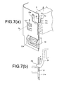
- FIG. 7( a ) shows a side cross-sectional view of the apparatus of FIG. 6 ;
- FIG. 7( b ) is an explanatory view illustrating action of a biasing member;
- FIG. 8 is an explanatory view showing a release state of the carriage in the apparatus of FIG. 4 ;
- FIG. 9 is a side cross-sectional view of FIG. 8 .
- FIG. 10 shows a modification of the biasing member according to the invention, where FIG. 10( a ) is an explanatory view showing a lock state, and FIG. 10( b ) is an explanatory view showing a release state.
- an optical carriage (hereinafter, referred to as a “carriage”) 6 is comprised of a carriage frame 15 , light source 9 , reflecting mirrors 10 , condenser lens 7 , and image reading sensor 8 .
- the carriage frame 15 is made of a resin rich in heat resistance, and is installed with the light-source lamp 9 , imaging device (reflecting mirrors and condenser lens), and the image reading sensor 8 .
- the carriage frame 15 is formed a read opening 11 corresponding to an effective reading width Ls (see FIG. 1 ) of an original sheet, light is applied to the original sheet through the read opening 11 , and the reflected light is applied onto the image reading sensor 8 by the imaging device. Then, the carriage frame 15 is provided with engagement portions 6 a , 6 b engaging in first and second rail members 12 a , 12 b prepared in a scanner unit A.
- the first and second rail members are formed of a guide rod 12 a and guide rail 12 , a pair of the members are disposed to the left and right of a platen 2 described later, and the carriage frame 15 is provided with a bearing engagement portion 6 a being fitted with the guide rod 12 a and a slide engagement portion 6 b engaging in the guide rail 12 b.
- the light source 9 is comprised of a light-source lamp applying linear light along the effective reading width Ls formed in the read opening 11 of the carriage frame 15 .
- “ 15 a ” shown in the figure denotes a heat-resistant lamp cover
- “ 15 b ” shown in the figure denotes a reflector.
- the light source (light-source lamp) 9 adopts a reflective structure for applying light of a rod-shaped emitter such as a fluorescent lamp and xenon lamp or dot-shaped light-emitting devices as linear light.
- a rod-shaped emitter such as a fluorescent lamp and xenon lamp or dot-shaped light-emitting devices as linear light.
- the reflecting mirrors 10 are comprised of a plurality of mirrors as appropriate so as to form an optical path length with a predetermined length.
- a first mirror 10 a reflects the reflected light of the original image toward a second mirror 10 b
- the light is guided to a fourth mirror 10 d from a third mirror 10 c
- the light from the fourth mirror 10 d is guided to the condenser lens 7 via the second mirror 10 b
- the first mirror 10 a and a fifth mirror 10 e the reflected light of the original image is not limited to such optical path formation, and for example, it is possible to form an optical path using two, first and second, mirrors.
- the condenser lens 7 is formed of a single or plurality of imaging lenses, and condenses the reflected light of the original image sent from the reflecting mirror 10 on the image reading sensor 8 for image formation.
- the image reading sensor 8 is comprised of a photoelectric conversion sensor such as CCD, and performs photoelectric conversion on the reflected light of the original image sent from the condenser lens 7 .
- the image reading sensor 8 shown in the figure is comprised of a color line sensor, where three lines of sensor elements forming pixels of R (Red), G (Green) and B (Blue) are arranged in line form.
- the image reading sensor 8 with such a configuration is attached to a substrate 8 a , and the substrate 8 a is secured to the carriage frame 15 .
- the carriage 6 is supported slidably by the first rail member (guide rod) 12 a and second rail member (guide rail) 12 b spaced a distance apart from each other in the scanning direction (x direction in FIG. 3 ) of the platen 2 . Then, the carriage 6 is bearing-engaged in a circular rail surface (bearing engagement portion) 6 a of the first rail member 12 a , and at the same time, is mount-engaged in the flat-shaped rail surface (slide engagement portion) 6 b of the second rail member 12 b .
- the first rail member 12 a and second rail member 12 b are disposed in a frame 21 .
- the frame 21 is integrally formed in the external case 20 .
- the frame 21 shown in the figure is integrally formed in one side wall of the external case 20 as a reinforcing member.
- the lock mechanism of the invention is comprised of the frame 21 , lock member 22 and carriage 6 as shown in FIG. 4 , and the frame 21 is comprised of a sheet metal frame lined on the inner wall of the external case 20 .
- the biasing member 23 is integrally formed in the lock member 22 as an elastic piece, as described later. Then, an engagement portion 24 is formed in the lock member 22 , and an engagement receiving portion 25 is formed in the carriage 6 .
- the frame 21 is integrally formed in the external case 20 , and is provided with slit grooves 21 a , 21 b , 21 c for slidably supporting the lock member 22 , and in the slit grooves 21 a to 21 c are fitted and supported guide pins 22 a , 22 b , 22 c of the lock member 22 described later. Further, the frame 21 is provided with locking concave portions 21 d , 21 e to latch and lock a latch protrusion 23 r of the elastic piece (biasing member) 23 of the lock member 22 .
- the concave portion 21 d is disposed in a lock position (Ro), while the concave portion 21 e is disposed in a release position (Le), in the lock member 22 described later.
- the frame 21 is provided with a switch opening 21 f to expose an operation switch 30 of an apparatus power supply disposed inside the external case 20 to the outside of the apparatus.
- the lock member 22 is integrally provided with the elastic piece (biasing member) 23 , and hereinafter, this member is referred to as a slide member 22 .
- the slide member 22 is provided with the engagement portion 24 , guide pins 22 a , 22 b , 22 c , a shutter portion 22 . d to cover the operation switch 30 , and the elastic piece (biasing member) 23 .
- the guide pins 22 a , 22 b , 22 c are integrally embedded in the slide member 22 , and are configured in the shape adapting to the slit grooves 21 a , 21 b , 21 c of the frame 21 .
- the slide member 22 is attached to the frame 21 slidably. Then, in the slide member 22 , the lock position Ro and release position Le are set by slide operation.
- the engagement portion 24 is fitted into the engagement receiving portion 25 provided in the carriage 6 , described later, and is formed to be coupled to each other (movement restriction).
- the engagement portion 24 integrally formed in the slide member (lock member) 22 is configured in the shape mutually fitting with the engagement receiving portion 25 of the carriage 6 as shown in FIG. 4 , and the shape meets the following conditions.
- the engagement portion 24 is provided in a position such that the portion 24 is fitted into the engagement receiving portion 25 when the slide member (lock member) 22 is in the lock position Ro, while being released from the fit when the member 22 is in the release position Le.
- the engagement portion 24 is provided in the end edge (in the figure, the upper end edge) in the traveling direction of the slide member (lock member) 22 , and is configured to be locked and released from the lock by slide traveling of the slide member (lock member) 22 .
- the engagement portion 24 is fitted into the engagement receiving portion 25 of the carriage 6 , and restricts traveling in the scanning direction (x direction in FIG. 4 ) of the carriage 6 . Therefore, the engagement portion 24 is configured in the shape of latching the engagement receiving portion 25 so as to restrict movements in the scanning direction (x direction in FIG. 4 ).
- the lock state is shown in FIGS. 7( a ) and 7 ( b ), an engagement surface 24 x of the engagement portion 24 and an engagement surface 25 x of the engagement receiving portion 25 are mutually fitted as shown in the figure, and in this fit state, the carriage 6 is restricted in movements in the scanning direction (x direction in FIG. 4) and is fixed to this position.
- the engagement portion 24 is configured in the shape of applying the biasing force in the direction (z direction in FIG. 3 ) orthogonal to the scanning direction to the engagement receiving portion 25 in the lock position where the portion 24 is fitted with the engagement receiving portion 25 .
- the engagement surface 24 z comes into contact with the engagement surface 25 z of the engagement receiving portion 25 in the lock position.
- the carriage 6 is provided with the engagement receiving portion 25 as described above, and the engagement receiving portion 25 is restricted in movements in the scanning direction (x direction) in the lock state where the portion 25 is engaged with the engagement portion 24 of the lock member (slide member) 22 , concurrently undergoes the action force in the direction (z direction) orthogonal to the scanning direction (x direction), and increases engagement friction with the guide rail (second rail member) 12 b.
- the carriage driving member (driving belt) 27 is coupled to a driving motor not shown, and is configured to move the carriage 6 in the scanning direction (x direction) to read.
- the elastic piece (biasing member) 23 is integrally formed in the slide member 22 (lock member; the same in the following).
- the slide member 22 is made of a synthetic resin, and is integrally provided with the elastic piece (biasing member) 23 by mold forming.
- a base end portion 23 a is joined to the slide member 22 , and a front end portion 23 b becomes elastically deformed in the arrow direction shown in the figure (see FIG. 7( b )).
- the front end portion 23 b is provided with the latch protrusion 23 r , and the latch protrusion 23 r engages in the locking concave portions 21 d , 21 e as described previously formed on the opposite frame 21 side.
- the locking concave portion 21 d is provided in the lock position Ro
- the locking concave portion 21 e is provided in the release position Le
- the latch protrusion 23 r is kept in the position by its own elastic force in the state of engaging in each locking concave portion 21 d , 21 e.
- the elastic piece (biasing member) 23 is curved and deformed as shown in FIG. 7( b ) and exerts the elastic force in the arrow direction shown in the figure, in the state where the latch protrusion 23 r is fitted into the locking concave portion 21 d in the lock position Ro.
- the latch protrusion 23 r engages in the locking concave portions 21 d , 21 e , is kept in the position by its own elastic force, and is configured to exert the biasing force in the predetermined direction on the slide member 22 in the state of the lock position Ro.
- the predetermined direction is set at the direction of increasing friction between the carriage 6 and rail surface 12 br via the engagement portion 24 as described previously.
- the slide member 22 is provided with the shutter portion 22 d , and the shutter portion 22 is disposed in the switch opening 21 f formed in the frame 21 to cover part of the opening.
- the switch opening 21 f is disposed to expose the operation switch 30 disposed inside the external case to the outside.
- the shutter portion 22 d covers part of the switch opening 21 f to inhibit switch operation in the lock position Ro, while opening the switch opening 21 f to enable the switch operation in the release position Le.
- the shutter portion 22 d protrudes from the slide member 22 toward the opposite frame 21 side, and covers the switch opening 21 f formed in the frame 21 .
- this shutter portion 22 d acts also as an operation piece of the slide member 22 . Accordingly, the shutter portion 22 d protruding outside from the external case 20 is grasped to operate and move the slide member 22 between the lock position Ro and release position Le.
- FIGS. 6 and 7 show the lock state where the carriage 6 reciprocating along the first and second rail members 12 a , 12 b is fixed to the predetermined position.
- the slide member (lock member) 22 is held in the locking concave portion 21 d in the lock position Ro.
- the engagement portion 24 is fitted with the engagement receiving portion 25 of the carriage 6 , and the engagement surface 24 x restricts the position of the engagement surface 25 x so as to inhibit the carriage 6 from traveling in the scanning direction (x direction) (see FIG. 7 ).
- the engagement portion 24 undergoes the biasing force F in the orthogonal direction (z direction) orthogonal to the scanning direction (x direction) from the elastic piece (biasing member) 23 as shown in FIG. 7( b ), and this biasing force F acts, in the direction shown by the arrow, on the engagement surface 25 z of the engagement receiving portion 25 of the carriage 6 by the engagement surface 24 z .
- This biasing force F acts on the carriage 6 to increase engagement friction with the guide rail (second rail member) 12 b .
- the shutter portion 22 d of the slide member 22 covers the operation opening of the operation switch 30 , and is held in the position to inhibit the operation.
- FIGS. 8 and 9 show the release state of the lock mechanism.
- the slide member 22 is held in the locking concave portion 21 e in the release position Le.
- the engagement portion 24 is spaced apart from the engagement receiving portion 25 of the carriage 6 , and thus, the portions 24 and 25 are mutually released from the engagement.
- the carriage 6 is released from the lock state and becomes free.
- the shutter portion 22 d moves outward from the switch opening 21 f to enable the switch to be operated.
- the biasing member for locking the lock member (slide member) 22 in the lock position Ro and release position Le is formed of the elastic piece 23 , and as shown in FIG. 10 , the biasing means can be formed of a spring 26 for biasing the lock member (slide member) 22 in the z direction in FIG. 3 .
- the other configuration is the same as in the foregoing, and specific descriptions are omitted.
Landscapes
- Engineering & Computer Science (AREA)
- Multimedia (AREA)
- Signal Processing (AREA)
- Optical Systems Of Projection Type Copiers (AREA)
- Facsimile Scanning Arrangements (AREA)
Abstract
Description
Claims (6)
Applications Claiming Priority (2)
| Application Number | Priority Date | Filing Date | Title |
|---|---|---|---|
| JP2009-150700 | 2009-06-25 | ||
| JP2009150700A JP5327798B2 (en) | 2009-06-25 | 2009-06-25 | Optical reader |
Publications (2)
| Publication Number | Publication Date |
|---|---|
| US20100328736A1 US20100328736A1 (en) | 2010-12-30 |
| US8773735B2 true US8773735B2 (en) | 2014-07-08 |
Family
ID=43380403
Family Applications (1)
| Application Number | Title | Priority Date | Filing Date |
|---|---|---|---|
| US12/801,641 Active 2032-12-19 US8773735B2 (en) | 2009-06-25 | 2010-06-18 | Optical reader apparatus |
Country Status (2)
| Country | Link |
|---|---|
| US (1) | US8773735B2 (en) |
| JP (1) | JP5327798B2 (en) |
Cited By (1)
| Publication number | Priority date | Publication date | Assignee | Title |
|---|---|---|---|---|
| US9444958B2 (en) * | 2014-08-29 | 2016-09-13 | Kyocera Document Solutions Inc. | Image reading device and image forming apparatus including the same |
Families Citing this family (11)
| Publication number | Priority date | Publication date | Assignee | Title |
|---|---|---|---|---|
| JP5070143B2 (en) * | 2008-06-23 | 2012-11-07 | ニスカ株式会社 | Image reading device |
| JP5517214B2 (en) | 2011-04-11 | 2014-06-11 | Necアクセステクニカ株式会社 | Image reading device |
| JP5772463B2 (en) * | 2011-10-03 | 2015-09-02 | ブラザー工業株式会社 | Image reading device |
| JP5776476B2 (en) | 2011-10-03 | 2015-09-09 | ブラザー工業株式会社 | Image reading device |
| US9363398B2 (en) | 2013-01-21 | 2016-06-07 | Hewlett Packard Development Company, L.P. | Interlocking assembly for a scanning unit |
| US10143383B2 (en) * | 2014-07-08 | 2018-12-04 | Iweecare Co., Ltd. | Attachable monitoring device |
| JP6727009B2 (en) * | 2016-04-12 | 2020-07-22 | キヤノンファインテックニスカ株式会社 | Supporting structure for running body |
| JP6997961B2 (en) * | 2017-03-14 | 2022-02-04 | 株式会社リコー | Image reader and image forming device |
| JP6690599B2 (en) * | 2017-05-30 | 2020-04-28 | 京セラドキュメントソリューションズ株式会社 | Insert member and image reading device |
| US20200093375A1 (en) * | 2018-09-25 | 2020-03-26 | Iweecare Co., Ltd. | Sensing system and sensing assembly |
| JP7278840B2 (en) * | 2019-04-09 | 2023-05-22 | キヤノン株式会社 | Image reader |
Citations (5)
| Publication number | Priority date | Publication date | Assignee | Title |
|---|---|---|---|---|
| JPH06186647A (en) | 1992-12-22 | 1994-07-08 | Ricoh Co Ltd | Traveling body driving device |
| JPH10173841A (en) | 1996-12-09 | 1998-06-26 | Ricoh Co Ltd | Document loading table |
| JPH10221623A (en) | 1996-12-19 | 1998-08-21 | Hewlett Packard Co <Hp> | Locking system |
| JP2002214720A (en) | 2001-01-15 | 2002-07-31 | Fuji Xerox Co Ltd | Image reader and image forming apparatus using the same |
| JP2007110466A (en) | 2005-10-14 | 2007-04-26 | Canon Inc | Image reading apparatus and image forming apparatus |
-
2009
- 2009-06-25 JP JP2009150700A patent/JP5327798B2/en active Active
-
2010
- 2010-06-18 US US12/801,641 patent/US8773735B2/en active Active
Patent Citations (5)
| Publication number | Priority date | Publication date | Assignee | Title |
|---|---|---|---|---|
| JPH06186647A (en) | 1992-12-22 | 1994-07-08 | Ricoh Co Ltd | Traveling body driving device |
| JPH10173841A (en) | 1996-12-09 | 1998-06-26 | Ricoh Co Ltd | Document loading table |
| JPH10221623A (en) | 1996-12-19 | 1998-08-21 | Hewlett Packard Co <Hp> | Locking system |
| JP2002214720A (en) | 2001-01-15 | 2002-07-31 | Fuji Xerox Co Ltd | Image reader and image forming apparatus using the same |
| JP2007110466A (en) | 2005-10-14 | 2007-04-26 | Canon Inc | Image reading apparatus and image forming apparatus |
Cited By (1)
| Publication number | Priority date | Publication date | Assignee | Title |
|---|---|---|---|---|
| US9444958B2 (en) * | 2014-08-29 | 2016-09-13 | Kyocera Document Solutions Inc. | Image reading device and image forming apparatus including the same |
Also Published As
| Publication number | Publication date |
|---|---|
| JP2011009987A (en) | 2011-01-13 |
| US20100328736A1 (en) | 2010-12-30 |
| JP5327798B2 (en) | 2013-10-30 |
Similar Documents
| Publication | Publication Date | Title |
|---|---|---|
| US8773735B2 (en) | Optical reader apparatus | |
| EP2026556B1 (en) | Multi-functional device having scanner module and image scanning apparatus employing the scanner module | |
| US9357090B2 (en) | Image processing device | |
| US7884974B2 (en) | Image sensor, image sensor unit, and image scanning device | |
| JP4438713B2 (en) | Image reading device | |
| JP5395204B2 (en) | Image sensor unit, image reading apparatus, and image forming apparatus | |
| EP2346237A1 (en) | Image scanning device | |
| US20140104660A1 (en) | Carrier and image scanning apparatus having the carrier | |
| US8837008B2 (en) | Image reading apparatus | |
| JPH11289430A (en) | Image reading device and image forming device | |
| JP4890799B2 (en) | Scanning apparatus and image reading apparatus | |
| US20060203300A1 (en) | Image scanning unit and image forming apparatus having the same | |
| JP6152638B2 (en) | Reading apparatus and image forming apparatus | |
| JP4296673B2 (en) | Scanner holding structure | |
| US10003711B2 (en) | Light irradiation device, image reading device, and image forming apparatus | |
| JP4500028B2 (en) | Scanner device and image forming apparatus | |
| JP5162355B2 (en) | Image reading device | |
| JP4478393B2 (en) | Image reading device | |
| JP2008005140A (en) | Image reading apparatus and image forming apparatus equipped therewith | |
| JP4481742B2 (en) | Image reading device | |
| JP5195549B2 (en) | Image reading apparatus and image forming apparatus provided with image reading apparatus | |
| JPH1127462A (en) | Scanner lock mechanism | |
| JP2009212652A (en) | Original reader | |
| US7344075B2 (en) | Scanning apparatus and guiding mechanism thereof | |
| JP2004138800A (en) | Scanner unit holding mechanism |
Legal Events
| Date | Code | Title | Description |
|---|---|---|---|
| AS | Assignment |
Owner name: NISCA CORPORATION, JAPAN Free format text: ASSIGNMENT OF ASSIGNORS INTEREST;ASSIGNOR:OZAWA, JUNYA;REEL/FRAME:024608/0499 Effective date: 20100520 Owner name: SEIKO EPSON CORPORATION, JAPAN Free format text: ASSIGNMENT OF ASSIGNORS INTEREST;ASSIGNOR:OZAWA, JUNYA;REEL/FRAME:024608/0499 Effective date: 20100520 |
|
| STCF | Information on status: patent grant |
Free format text: PATENTED CASE |
|
| MAFP | Maintenance fee payment |
Free format text: PAYMENT OF MAINTENANCE FEE, 4TH YEAR, LARGE ENTITY (ORIGINAL EVENT CODE: M1551) Year of fee payment: 4 |
|
| MAFP | Maintenance fee payment |
Free format text: PAYMENT OF MAINTENANCE FEE, 8TH YEAR, LARGE ENTITY (ORIGINAL EVENT CODE: M1552); ENTITY STATUS OF PATENT OWNER: LARGE ENTITY Year of fee payment: 8 |
|
| MAFP | Maintenance fee payment |
Free format text: PAYMENT OF MAINTENANCE FEE, 12TH YEAR, LARGE ENTITY (ORIGINAL EVENT CODE: M1553); ENTITY STATUS OF PATENT OWNER: LARGE ENTITY Year of fee payment: 12 |