US8773652B2 - Method and device for aligning a lens with an optical system - Google Patents
Method and device for aligning a lens with an optical system Download PDFInfo
- Publication number
- US8773652B2 US8773652B2 US13/384,143 US200913384143A US8773652B2 US 8773652 B2 US8773652 B2 US 8773652B2 US 200913384143 A US200913384143 A US 200913384143A US 8773652 B2 US8773652 B2 US 8773652B2
- Authority
- US
- United States
- Prior art keywords
- lens
- mtf
- image
- optical system
- sagittal
- Prior art date
- Legal status (The legal status is an assumption and is not a legal conclusion. Google has not performed a legal analysis and makes no representation as to the accuracy of the status listed.)
- Expired - Fee Related, expires
Links
Images


Classifications
-
- G—PHYSICS
- G02—OPTICS
- G02B—OPTICAL ELEMENTS, SYSTEMS OR APPARATUS
- G02B27/00—Optical systems or apparatus not provided for by any of the groups G02B1/00 - G02B26/00, G02B30/00
- G02B27/62—Optical apparatus specially adapted for adjusting optical elements during the assembly of optical systems
-
- G—PHYSICS
- G01—MEASURING; TESTING
- G01M—TESTING STATIC OR DYNAMIC BALANCE OF MACHINES OR STRUCTURES; TESTING OF STRUCTURES OR APPARATUS, NOT OTHERWISE PROVIDED FOR
- G01M11/00—Testing of optical apparatus; Testing structures by optical methods not otherwise provided for
- G01M11/02—Testing optical properties
- G01M11/0221—Testing optical properties by determining the optical axis or position of lenses
-
- G—PHYSICS
- G02—OPTICS
- G02B—OPTICAL ELEMENTS, SYSTEMS OR APPARATUS
- G02B13/00—Optical objectives specially designed for the purposes specified below
- G02B13/001—Miniaturised objectives for electronic devices, e.g. portable telephones, webcams, PDAs, small digital cameras
- G02B13/0015—Miniaturised objectives for electronic devices, e.g. portable telephones, webcams, PDAs, small digital cameras characterised by the lens design
-
- G—PHYSICS
- G02—OPTICS
- G02B—OPTICAL ELEMENTS, SYSTEMS OR APPARATUS
- G02B7/00—Mountings, adjusting means, or light-tight connections, for optical elements
- G02B7/02—Mountings, adjusting means, or light-tight connections, for optical elements for lenses
- G02B7/023—Mountings, adjusting means, or light-tight connections, for optical elements for lenses permitting adjustment
Definitions
- the invention relates to the manufacturing of multi lenses optical modules, such as, but not limited to, the optical modules used in the camera for mobile phones.
- the invention relates in particular to a method and device for aligning a lens with an optical system, the optical system comprising for example one lens or more.
- the invention relates more particularly to a method and device for implementing a fast coarse pre-alignment of the lens with the optical system.
- the coarse pre-alignment allows to subsequently rapidly conduct a precise alignment of the lens with the optical system.
- FIG. 1 shows an elevation view of the main elements composing an optical module 10 that can be used in a camera of a mobile phone.
- a support 12 comprises a cylindrical recess 14 having an axis 16 and a base 18 .
- Base 18 comprises an aperture around axis 16 .
- a number of lens assemblies 20 a , 22 a ; 20 b , 22 b , 20 c , 22 c , 20 d , 22 d (four are illustrated) comprising each a spacer ring ( 20 a , 20 b , 20 c , 20 d ) followed by a lens ( 22 a , 22 b , 22 c , 22 d ) are maintained within the recess 14 with a cylindrical barrel 24 that comprises an aperture around axis 16 .
- a sensor 26 is eventually provided such that it receives light crossing the lenses along axis 16 . Sensor 26 can form part of the module or can be provided separately.
- the quality of an optical module such as module 10 depends strongly on the alignment of the optical axis of the different lenses ( 22 a , 22 b , 22 c , 22 d ) composing the module.
- the focal length of the module which is the distance from the optical center of the lens assembly to the sensor onto which is formed the image, is constraint by the small dimension of the phone, and must generally range from 1 mm to 6 mm.
- Such a short focal distance is obtained by using a lens assembly combining several lenses having a high convergence, ranging approximately from 100 to 1000.
- High quality modules composed of more than 3 lenses currently require at least one alignment made with an accuracy of 1 to 5 microns. Making such alignments is very time consuming.
- An embodiment of the invention comprises pre-aligning a lens with an optical system by: starting with the lens roughly aligned on the optical system, following the steps of: a/calculate coarse MTF for the combined lens & optical system on at least four coarse measurement locations, b/move toward location of lowest coarse MTF by a predetermined distance, c/goto a/ unless the predetermined condition are reached).
- Another embodiment of the invention comprises pre-aligning a lens with an optical system by: starting with the lens roughly aligned on the optical system; and correcting the position of the lens until the values of Modulation Transfer Functions calculated for a pattern comprising a combination of a Sagittal pattern and a Tangential pattern at four coarse measurement locations are in predetermined ranges.
- Another embodiment of the invention comprises a process for pre-aligning a lens with an optical system, the process comprising:
- a lens and an optical system having an optical axis wherein the lens is apt to be aligned with the optical system to form on an image plane an image of a source object, the image having top, bottom, left and right edges;
- C-MTF Combination Modulation Transfer Functions
- correcting the position of the lens until the values of the four C-MTFs are in predetermined ranges comprises repeating the steps:
- the method above further comprises:
- the method above further comprises:
- a source object having, in its four coarse measurement locations, a checkerboard pattern having rows and columns respectively parallel and perpendicular to the top-to-bottom axis of the object.
- the two axes of the image comprising the coarse measurement locations follow the diagonals of the image, and the four coarse measurement locations are situated at the four corners of the image.
- coarsely positioning the lens comprises aligning the center of the source object with the optical axis of the optical system; and positioning the lens with respect to the optical system such that the image of the center of the source object formed on the image plane coincides with the intersection of the image plane and the optical axis of the optical system.
- Another embodiment of the present invention comprises a process for aligning a lens with an optical system, said process including:
- first and second Sagittal and Tangential Modulation Transfer Functions of the combined lens and optical system, calculated at the first and second precise measurement locations are such that difference between the Sagittal Modulation Transfer Functions of the first and second precise measurement locations and difference between the Tangential Modulation Transfer Functions of the first and second precise measurement locations are minimal, each of the Modulation Transfer Functions being above a first predetermined threshold;
- the first and second precise measurement locations are situated at the middle of the top and bottom of the image, the first precise positioning axis being the vertical axis of the image and the first and second Sagittal and Tangential Modulation Transfer Functions being Top and Bottom Sagittal and Tangential Modulation Transfer Functions; and
- the third and fourth precise measurement locations are situated at the middle of the left and right of the image, the second precise positioning axis being the horizontal axis of the image and the third and fourth Sagittal and Tangential Modulation Transfer Functions being Left and Right Sagittal and Tangential Modulation Transfer Functions.
- adjusting the position of the lens along a line parallel to the vertical axis of the image comprises:
- TS-MTF Top Sagittal Modulation Transfer Function
- TT-MTF Top Tangential Modulation Transfer Function
- BS-MTF Bottom Sagittal Modulation Transfer Function
- BT-MTF Bottom Tangential Modulation Transfer Function
- ⁇ 1, ⁇ 1, n1, n2 are predetermined weighting factors
- said adjusting the position of the lens along a line parallel to the horizontal axis of the image comprises:
- LS-MTF Left Sagittal Modulation Transfer Function
- LT-MTF Left Tangential Modulation Transfer Function
- RS-MTF Right Sagittal Modulation Transfer Function
- R-MTF Right Tangential Modulation Transfer Function
- a value GmH ⁇ 2 ((TS-MTF) ⁇ (BS-MTF)) n3 + ⁇ 2((TT-MTF) ⁇ (BT-MTF)) n4 reaches a minimum below a fourth predetermined threshold, where ⁇ 2, ⁇ 2, n3, n4 are predetermined weighting factors.
- GmV reaches a minimum when the variation of GmV changes from negative to positive
- GmH reaches a minimum when the variation of GmH changes from negative to positive.
- said adjusting the position of the lens along a line parallel to the vertical axis of the image comprises:
- said adjusting the position of the lens along a line parallel to the horizontal axis of the image comprises:
- An embodiment of the invention further comprises providing an image sensor capable of sensing the image of the source object on the image plane.
- the present invention also comprises an apparatus provided for implementing any of the methods above.
- the present invention also comprises a source object to be used in an process for pre-aligning a lens with an optical system, the source object having, in each of four coarse measurement locations situated close to the edges of the object along two axes crossing the center of the object, a pattern comprising a combination of a Sagittal pattern and a Tangential pattern.
- the source object further comprises, in each of four precise measurement locations situated close to the edges of the object along first and second precise positioning axes crossing the center of the object, a pattern comprising a juxtaposition of a Sagittal pattern and a Tangential pattern.
- the source object has a top, a bottom, a left and a right; wherein:
- the middle of the top of the object comprises a juxtaposition of a Sagittal pattern and a Tangential pattern
- the middle of the bottom of the object comprises a juxtaposition of a Sagittal pattern and a Tangential pattern
- the middle of the left of the object comprises a juxtaposition of a Sagittal pattern and a Tangential pattern
- the middle of the right of the object comprises a juxtaposition of a Sagittal pattern and a Tangential pattern
- the top-left, top-right, bottom left and bottom right corners of the object comprise each a combination of a Sagittal pattern and a Tangential pattern.
- the juxtaposition of a Sagittal pattern and a Tangential pattern comprises a set of lines parallel to the first precise positioning axis of the object juxtaposed with a set of lines parallel to the second precise positioning axis of the object, each set of lines being on one side of the corresponding precise positioning axis of the object.
- the combination of a Sagittal pattern and a Tangential pattern comprises a checkerboard pattern having rows and columns respectively parallel and perpendicular to a top-to-bottom axis of the object.
- the juxtaposition of a Sagittal pattern and a Tangential pattern comprises a set of lines slanted by a few degrees with respect to the parallel to the first precise positioning axis of the object juxtaposed with a set of lines slanted by a few degrees with respect to the parallel to the second precise positioning axis of the object, each set of lines being on one side of the corresponding precise positioning axis of the object.
- the combination of a Sagittal pattern and a Tangential pattern comprises a checkerboard pattern having rows and columns respectively slanted by a few degrees with respect to the parallel and perpendicular to a top-to-bottom axis of the object
- An embodiment of the invention comprises a process for pre-aligning a lens with an optical system, the process comprising: providing a lens and an optical system having an optical axis, wherein the lens is apt to be aligned with the optical system to form on an image plane an image of a source object, the image having top, bottom, left and right edges; coarsely positioning the lens with respect to the optical system; and repeating the steps comprising:
- C-MTF Combination Modulation Transfer Function
- said calculating the four Combined Modulation Transfer Function (C-MTF) of the combined lens and optical system comprises, at each of the coarse measurement location of the image, calculating a Modulation Transfer Function for a pattern comprising a combination of a Sagittal pattern and a Tangential pattern.
- C-MTF Combined Modulation Transfer Function
- FIG. 1 shows an elevation view of the main elements composing an optical module.
- FIGS. 2 a and 2 b illustrate the Sagittal and Tangential directions with respect to an optical system.
- FIG. 3 illustrates a field of view of an optical module for an alignment according to the present invention.
- FIG. 4 illustrates the changes of the values of TS-MTF and BS-MTF, and of the resulting values of V ⁇ S as the top lens moves along the Y axis with respect to the fixed stack/optical system
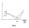
- FIG. 5 illustrates the changes of the values of V ⁇ S and V ⁇ T as the top lens moves along the Y axis with respect to the fixed stack/optical system.
- FIG. 6 illustrates a complete process for positioning a lens according to an embodiment of the invention.
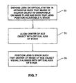
- FIG. 7 illustrates a process for coarsely positioning a lens according to an embodiment of the invention.
- FIG. 8 illustrates a process for pre-positioning a lens according to an embodiment of the invention.
- FIG. 9 illustrates a process for precisely positioning a lens along the Y axis according to an embodiment of the invention.
- FIG. 10 illustrates a process for precisely positioning a lens along the X axis according to an embodiment of the invention.
- FIG. 11 shows a source object according to an embodiment of the invention.
- the present invention relates in particular to modules designed such that the lens on top of the lens stack concentrates most of the convergence of the module, and the remaining lenses have a low convergence, and are just intended to correct aberrations without modifying significantly the convergence.
- the lens on top of the stack is referred to as the top lens, and the others lenses are referred to as the fixed stack.
- the present invention relates to the method to perform a precise and fast alignment of the top lens with respect to the optical axis of the fixed stack.
- the optical axis of the stack is practically defined as the optical axis of one of the lenses in the stack, for example the bottom lens.
- the alignment of the top lens with the optical system forming the fixed stack is optimal when the optical quality of the module (lens+optical system) is maximal.
- the optical quality can be characterized by the MTF (Modulation Transfer Function. See (1)) measured in the two preferential directions: Sagittal (equivalent to Vertical for a human observer standing upright) and Tangential (Horizontal for the same observer).
- a punctual object A has an image which is also punctual.
- the object, the image and the optical axis are in the same plane, which is the Sagittal plane.
- a linear object which intersects the axis, being all contained in the Sagittal plane has an image which is also in the Sagittal plane.
- the Sagittal direction is defined in the image plane (perpendicular to the optical axis) by the line crossing the point A and the optical center O.
- the Tangential plane is the plane which contains the object A and is perpendicular to the Sagittal plane.
- the Tangential direction is defined in the image plane by the line perpendicular to the Sagittal direction and passing by A.
- the MTF can then briefly be described as follows, assuming that the optical system allows forming an image of an object.
- the MTF is the modulus of the complex OTF, or Optical Transfer Function, which is the Fourier transform in the spatial frequency domain of the function which defines the illumination of the image of a punctual object in the spatial dimension domain.
- An object in the space domain can be decomposed into small elements, each of them being the sum of its spatial frequency components, and the illumination of the image is the sum of the image of all spatial components, multiplied by the modulus of the OTF.
- Imax and Imin are respectively the maximum and the minimum illumination observed.
- the modulus i.e. the MTF, is then a scalar number which varies from zero to one.
- the scale to measure the illumination is arbitrary, but it is a general practice to take a linear scale from a zero which corresponds to a black and a 1 which corresponds to a white, although it would be possible to use a non linear scale.
- the MTF in one point of the image is rigorously defined when the spatial frequency has a sinusoidal variation.
- the image, and so the object cannot be punctual and must be of finite dimensions to be measured.
- a generally accepted good approximation of the MTF is done when the object is a pattern of black and white lines which occupies a small part of the Field of View (FOV) of the optical system, in the range of 1% to 5%.
- An object/pattern for calculating a Sagittal MTF cannot be contained in one single Sagittal plane; if the pattern is composed of parallel lines. One of the parallel lines line is then contained in the Sagittal plane, the others extend in the Tangential direction.
- an object/pattern for calculating a Tangential MTF cannot be contained in one single Sagittal plane; if the pattern is composed of parallel lines. One of the parallel lines line is then contained in the Tangential plane, the others extend in the Sagittal direction.
- the Sagittal MTF (S-MTF) is generally different from the Tangential MTF (T-MTF), the difference measuring the Astigmatism of the optical system.
- the S-MTF and the T-MTF components depend on the location of the point of the image seen through the optical system where they are measured: they are generally maximal at the center of the image formed by the system, and degrade when the Field of View (see (1)) increases.
- the optical quality is usually characterized by the MTF components S and T at the center and at the center of the extremities of the Field of View, Left and Right, Top and Bottom as shown on FIG. 3 .
- FIG. 3 illustrates very schematically a Field of View 30 , having a center 32 , a center of left extremity/edge 34 , a center of right extremity/edge 36 , a center of top extremity/edge 38 and a center of bottom extremity/edge 40 .
- TOP ( 38 ) and BOTTOM ( 40 ) are aligned along the vertical direction, and LEFT ( 34 ) and RIGHT ( 36 ) are aligned along the horizontal direction.
- the optical characteristic of the module would be symmetric with respect to the center as follows:
- TOP S-MTF (TS-MTF), calculated in 38 , would be equal to the BOTTOM S-MTF (BS-MTF), calculated in 40 ;
- T-MTF TOP T-MTF
- BT-MTF BOTTOM T-MTF
- the present invention provides for using a module where the lenses that compose the fixed stack/optical system are not perfectly aligned.
- the inventors have noted that there is a position of the top lens with respect to the stack for which the differences in MTF are globally minimal, where the de-centering of the top lens with respect to the theoretical optical axis of the module gives the best compensation of the de-centering of the lenses of the fixed stack.
- This global minima can be defined separately for the vertical and horizontal directions by the minimum of the sum of the differences between the TOP and BOTTOM MTF and respectively between the LEFT and RIGHT MTF:
- ⁇ and ⁇ are predetermined weighting coefficients with ⁇ > ⁇ .
- GmV ⁇ ((TS-MTF) ⁇ (BS-MTF)) n1 + ⁇ ((TT-MTF) ⁇ (BT-MTF))
- n1 and n2 are predetermined weighting coefficients.
- the optical module is calculated to make an image which center is ideally positioned at the optical center, at the intersection of the optical axis of the module and the image plane. Due to the imperfection in the alignment of the lenses which compose the module, these two centers do not coincide, but they are close, which means, translated in mathematical terms, that the center of the image is an approximation of the solution of determining the optical center.
- the center of the image is represented by reference 32 in FIG. 3 .
- the two axes, respectively parallel to the vertical and horizontal directions which pass through O are the Y and X axis of the image, as shown of FIG. 3 .
- FIG. 4 illustrates the changes of the values of TS-MTF and BS-MTF, and of the resulting values of V ⁇ S as the top lens moves along the Y axis with respect to the fixed stack/optical system.
- the function V ⁇ S varies from a value close to zero to a relative maximum, then from the maximum to a relative minimum, then to a relative maximum, and again to a value close to zero, as schematized in FIG. 4 .
- V ⁇ T varies in a similar way (not shown on FIG. 4 ), albeit along a different curve than V ⁇ S.
- a position where the lens is aligned with the fixed stack corresponds to [V ⁇ S+V ⁇ T] as close as possible to zero (minimal), which means that V ⁇ S and V ⁇ T must each be close to zero; however the initial and final values cannot be a solution as they correspond to all MTF values also close to zero, as the farther the lens is from the optical center, the lower the MTF, as explained before.
- These initial and final solutions must be ignored to allow keeping only the point where V ⁇ S is minimal, while the MTF are above a given threshold.
- Such threshold depends on the performances of the module, but can for example be chosen in the range of 30% of the MTF calculated for a theoretically perfect alignment of the lenses of the module.
- V ⁇ S may also present local minima, as shown on FIG. 4 , but we have to eliminate as well these solutions, as we are looking for the point for which the function V ⁇ S reaches an absolute minima. A similar reasoning can be done for V ⁇ T.
- the point for which V ⁇ S is minimal does not coincide with the point where V ⁇ T is minimal.
- the present invention provides for determining the position of the lens with respect to the fixed stack for which the function
- this point correspond to the intersection of the graphs of V ⁇ S and V ⁇ T with the lowest value and for which the variation of the function V ⁇ S+V ⁇ T is changing from negative to positive, as shown on FIG. 5 .
- FIG. 5 illustrates the changes of the values of V ⁇ S and V ⁇ T as the top lens moves along the Y axis with respect to the fixed stack/optical system.
- the point can be determined by a calculation of the barycenter of the solutions of V ⁇ S and V ⁇ T.
- point A is the point on the Y axis which gives the best balance of the Top and Bottom MTF, both for S and T components.
- the point B is the solution of the global minimization of the differences between Top and Bottom MTF and Left and Right MTF, both for S and T components.
- a method according to the invention allows determining the optimal alignment of the top lens on the fixed stack by following for example the steps:
- top lens At a pre-aligned position of the top lens, make an image of an object through the complete module (top lens plus fixed stack).
- the criteria used to determine the best alignment require the computation of the MTF in various points of the image, and then the time to perform the alignment will depend on:
- the number N of lens positions to examine before reaching an appropriate position is the number N of lens positions to examine before reaching an appropriate position.
- the total time to make the alignment is N ⁇ (T 1 +T 2 +T 3 ).
- T 1 , T 2 , T 3 depend on the equipment which is used: the type of sensor (with parallel or serial output), the speed of computation of the processor used to calculate the MTFs, the speed of the motors used to move from one lens position to another, while N depends on the method used to select a position.
- the inventors have noticed that in the nominal design of the module, the center of the image of the observed object must coincide with the intersection of the optical axis of the module with the image plane.
- the present invention provides for initially moving the top lens so that these centers coincide, thus coarsely positioning the lens close to its best aligned position.
- the inventors have also noticed that, as the best aligned position of the lens gives the best possible balance for S and T, both between the Top and Bottom locations and Left and Right locations, it is also balancing the S MTF between the opposite corners of the image, and the same for T MTF.
- UL Upper Left
- UR Upper Right
- LL Lower Left
- LR Lower Right
- the inventors have noticed that one can accelerate the calculation in the corners by determining the MTF on a pattern which MTF is a combination of Sagittal and Tangential patterns.
- a Sagittal pattern is a pattern of lines along the projection of the Sagittal direction onto the image plane (or slightly slanted by a few degrees to avoid some artifacts described in the literature) and a Tangential pattern is a pattern of lines in the Tangential direction (or slightly slanted by a few degrees to avoid some artifacts described in the literature).
- the Inventors have determined that such Sagittal and Tangential patterns can be combined in a Checkerboard, and that the MTF computed on such a Checkerboard is a combination of Sagittal and Tangential MTF.
- Combination-MTF An MTF calculated from a combination of Sagittal and Tangential patterns such as a Checkerboard is hereafter referred to as a Combination-MTF, or C-MTF.
- pre-aligning the top lens comprises:
- the predetermined value and threshold for INX and the C-MTF are chosen in view of simulation data obtained for perfectly aligned lens and fixed stack.
- the predetermined step/displacement by which the lens is moved when adjusting its position according to the present invention can be defined as the minimum lens displacement that causes the MTF to change by an amount measurable using the MTF measurement means available for implementing the invention.
- the lens is satisfactorily pre-aligned with the fixed stack once the conditions of INX being below a predetermined value and of the calculated C-MTF being above a predetermined threshold are met.
- the lens or the stack may be of inferior quality if after a predetermined number of implementation of steps B and C above, INX is still above a predetermined value, or one of the calculated C-MTF is still below a predetermined threshold, the lens or the stack may be of inferior quality.
- steps B and C can then be repeated until one only of the two conditions of INX being below a predetermined value or any of the calculated C-MTF being above a predetermined threshold is met.
- the lens is moved to points A and B using the methods according to the invention as detailed above.
- the present invention requires a number of standard equipments to capture and display an image through the module, and to move the top lens.
- the Equipments must however be programmed to implement the novel and inventive methods according to the present invention.
- an embodiment of the present invention provides a specific source object that allows computing the various MTF detailed above.
- the dimensions of a source object according to the invention depend on the distance at which it is placed with respect to the module.
- the distance is usually the Hyperfocal distance of the module, but can be different depending on the distance at which the nominal performances of the module are specified.
- a source object according to the invention comprises for example the patterns required for the computation of the S and T components, in Top, Bottom, Left and Right, which are sets of lines which width is determined by the spatial frequency at which we want to make the analysis.
- S such pattern is a pattern of lines in the S direction as defined above (or slightly slanted by a few degrees to avoid some artifacts described in the literature) and for T a pattern of lines in the T direction (or slightly slanted by a few degrees to avoid some artifacts described in the literature).
- the four corners comprise for example each a checkerboard, which is a combination of patterns for S and T.
- the rows and columns of the checkerboards do not necessarily have the same spatial frequency as the S and T patterns. It may be convenient to use a lower spatial frequency as the lower the frequency, the higher the MTF. However, as also the lower the frequency, the lower the accuracy of the measurement, the choice of the spatial frequency used for the checkerboards is a compromise.
- an embodiment of the present invention comprises the following steps:
- the module having a lens that is to be aligned with a fixed stack is placed ( 70 ) on an appropriate dispositive as illustrated in FIG. 7 , such that:
- An image of a source object is formed through the module onto a sensor, able to transform the image of the source object into a signal which can be processed to calculate the MTF in any point of the image.
- the module is adjusted at a correct focal length by appropriate means. In case the focal length is modified by the position of the top lens, then appropriate means to keep a correct focus are provided.
- the source object comprises patterns which allow calculating separately the Sagittal (S) and Tangential (T) components of the MTF in the Top, Bottom, Left, and Right positions as shown on FIG. 3 .
- the positions are represented at the extremity of the Vertical and Horizontal Field of View (VFOV and HFOV) but it has to be noted that these positions can be defined at any value at the diagonal Field of View (FOV), depending on the specification of the module.
- FOV Field of View
- the Left and Right position can be defined at 60% FOV, and in this case the distance between the center and the position of the Left and Right patterns will be equal to 60% of the diagonal of the image.
- C-MTF Combination MTF value
- the source object also preferably comprises additional patterns that allow determining accurately the position of its center.
- the center of the source object is aligned ( 72 ) with the optical axis of the stack.
- the top lens is supposed to be held by appropriate means that allow moving the lens step by step with respect to the fixed stack with the necessary accuracy, for example 0.5 microns.
- the movement is controlled by appropriate means depending on the result of the calculation of the MTF performed on the image of the source object.
- the lens is then pre-positioned ( 62 ) as follows, as illustrated in FIG. 8 :
- the center of the top lens is then at a point called C.
- the position of the lens is then adjusted ( 64 ) along the Y axis as follows, as illustrated in FIG. 9 :
- the absolute minimum is characterized by:
- a predetermined limit for example 30% of the nominal value of the same MTF component determined by design
- V ⁇ S and V ⁇ T expressions having a value below a predetermined limit, for example 10% of the maximum of the (TS-MTF), (BS-MTF), (TT-MTF), (BT-MTF) expressions.
- the point which is selected is the point which satisfies also the condition above, and for which the values of the function V ⁇ S+V ⁇ T is the lowest, so that the function V ⁇ S+V ⁇ T reaches a minimum, characterized by the fact that the variation of this function changes from negative to positive.
- the center of the top lens is then at a point called A.
- the position of the lens is then adjusted ( 66 ) along the X axis as follows, as illustrated in FIG. 10 :
- the absolute minimum is characterized by:
- the point which is selected is the point which satisfies also the condition above, and for which the values of the function H ⁇ S+H ⁇ T is the lowest, so that the function H ⁇ S+H ⁇ T reaches a minimum, characterized by the fact that the variation of this function changes from negative to positive.
- the center of the top lens is then at a point called B which is the optimal centering of the top lens onto the fixed stack according to the present invention.
- the position of the lens is then fixed ( 68 ), for example using a sealant or any appropriate mechanical means.
- FIG. 11 shows an embodiment of source object according to the present invention.
- a source object 110 comprises, in each of four coarse measurement locations (the corners of the object in the example illustrated) situated close to the edges of the object along two axes (the diagonals in the example illustrated) crossing the center of the object, a pattern 112 comprising a combination of a Sagittal pattern and a Tangential pattern.
- the source object further comprises, in each of four precise measurement locations (the middle of the edges in the example illustrated) situated close to the edges of the objects along first and second precise positioning axes (the X and Y axes in the example illustrated) crossing the center of the object, a pattern 114 comprising a juxtaposition of a Sagittal pattern and a Tangential pattern.
- the juxtaposition of a Sagittal pattern and a Tangential pattern comprises a set of lines parallel to the first precise positioning axis of the object juxtaposed with (or near) a set of lines parallel to the second precise positioning axis of the object, each set of lines being on one side of the corresponding precise positioning axis of the object.
- the term “middle” of the image edge therefore refers here to a region generally near the middle edge of the image and big enough for containing the juxtaposition of a Sagittal pattern and a Tangential pattern.
- corner of the image refers to a region generally near the corner of the image and big enough for containing the combination of a Sagittal pattern and a Tangential pattern.
- the lines of the sets of lines can be slanted by a few degrees with respect to the parallel to the first and second precise positioning axis. Such slanting of the lines advantageously allows avoiding measurement errors when the image is to be captured by sensing elements that would be parallel to the lines.
- the combination of a Sagittal pattern and a Tangential pattern comprises a checkerboard pattern having rows and columns respectively parallel and perpendicular to the Y axis of the object.
- the rows and columns of the checkerboard can also be slanted by a few degrees with respect to the X and Y axes of the image.
- the present invention has been described with respect to a pre-alignment of the lens using patterns combining Sagittal and Tangential patterns at the corners of an image, followed by a precise alignment of the lens using patterns juxtaposing Sagittal and Tangential patterns at the top, bottom, left and right of the image.
- the present invention relates more generally to pre-aligning a lens with an optical system by: starting with the lens roughly aligned on the optical system, following the steps of: a/calculate a coarse MTF for the combined lens & optical system on at least four coarse measurement locations, b/move toward location of lowest coarse MTF by a predetermined distance, c/goto a/ unless the predetermined condition are reached).
- the present invention also relates more generally to pre-aligning a lens with an optical system by: starting with the lens roughly aligned on the optical system, correcting the position of the lens until the values of Modulation Transfer Functions calculated for a pattern comprising a combination of a Sagittal pattern and a Tangential pattern at four coarse measurement locations are in predetermined ranges.
- the invention has been described in relation with a pre-alignment using coarse MTFs calculated in the corners of the image, along the diagonals of the image, followed by a precise alignment using precise MTFs calculated along the X and Y axes of the image.
- the invention also relates to using coarse MTFs calculated in other positions disposed symmetrically along other lines crossing the center of the image.
- the invention also relates to using precise MTFs calculated in other positions disposed symmetrically along other lines crossing the center of the image.
- checkerboards following the X and Y axes of the image, but the checkerboards can also follow other directions, such as for example the diagonals of the picture.
- FIG. 1 illustrates an example of optical module where the top lens can be aligned according to the present invention, but the present invention applies to aligning any lens of any module with respect to an optical system of the module with which the lens is to be aligned.
- Such optical system may have one or more lens or not and/or may comprise a sensor or not.
- the invention was described in relation with the alignment of a top lens of a module, but is can also be used to align another lens of a module, if appropriate.
Landscapes
- Physics & Mathematics (AREA)
- General Physics & Mathematics (AREA)
- Optics & Photonics (AREA)
- Chemical & Material Sciences (AREA)
- Analytical Chemistry (AREA)
- Lens Barrels (AREA)
Abstract
Description
- Warren J. Smith. Modern Optical Engineering. McGraw-Hill.
MTF=(Imax−Imin)/(Imax+Imin),
GmV=((TS-MTF)−(BS-MTF))+((TT-MTF)−(BT-MTF)); and
GmH=((LS-MTF)−(RS-MTF))+((LT-MTF)−(RT-MTF))
GmV=α((TS-MTF)−(BS-MTF))+β((TT-MTF)−(BT-MTF))
GmV=((TS-MTF)−(BS-MTF))n1+((TT-MTF)−(BT-MTF))n2
GmV=α((TS-MTF)−(BS-MTF))n1+β((TT-MTF)−(BT-MTF))
(TS-MTF)−(BS-MTF)=VΔS
(TT-MTF)−(BT-MTF)=VΔT
(LS-MTF)−(RS-MTF)=HΔS
(LT-MTF)−(RT-MTF)=HΔT
So that GmV=VΔS+VΔT; and
GmH=HΔS+HΔT
INX=(Max(C-MTF)−(Min(C-MTF))/(Max(C-MTF)+(Min(C-MTF));
C-MTF=a·S+b·T,
where a and b are real or complex numbers.
INX=(Max(C-MTF)−(Min(C-MTF))/(Max(C-MTF)+(Min(C-MTF)).
GmV=((TS-MTF)−(BS-MTF))+((TT-MTF)−(BT-MTF)),
noted as explained above
GmV=VΔS+VΔT,
or a variant of this function using weighting coefficients as detailed above.
GmH=((LS-MTF)−(RS-MTF))+((LT-MTF)−(RT-MTF)), noted
GmH=HΔS+HΔT
Claims (13)
Applications Claiming Priority (1)
| Application Number | Priority Date | Filing Date | Title |
|---|---|---|---|
| PCT/IB2009/007151 WO2011018678A1 (en) | 2009-08-11 | 2009-08-11 | Method and device for aligning a lens with an optical system |
Publications (2)
| Publication Number | Publication Date |
|---|---|
| US20120113413A1 US20120113413A1 (en) | 2012-05-10 |
| US8773652B2 true US8773652B2 (en) | 2014-07-08 |
Family
ID=42008520
Family Applications (1)
| Application Number | Title | Priority Date | Filing Date |
|---|---|---|---|
| US13/384,143 Expired - Fee Related US8773652B2 (en) | 2009-08-11 | 2009-08-11 | Method and device for aligning a lens with an optical system |
Country Status (3)
| Country | Link |
|---|---|
| US (1) | US8773652B2 (en) |
| CN (1) | CN102483511B (en) |
| WO (1) | WO2011018678A1 (en) |
Cited By (2)
| Publication number | Priority date | Publication date | Assignee | Title |
|---|---|---|---|---|
| US20220124305A1 (en) * | 2020-10-20 | 2022-04-21 | Aptiv Technologies Limited | Device for Determining a Characteristic of a Camera |
| US20260065509A1 (en) * | 2024-08-27 | 2026-03-05 | Sony Interactive Entertainment Inc. | Varied density grid camera calibration chart |
Families Citing this family (74)
| Publication number | Priority date | Publication date | Assignee | Title |
|---|---|---|---|---|
| US11792538B2 (en) | 2008-05-20 | 2023-10-17 | Adeia Imaging Llc | Capturing and processing of images including occlusions focused on an image sensor by a lens stack array |
| US8866920B2 (en) | 2008-05-20 | 2014-10-21 | Pelican Imaging Corporation | Capturing and processing of images using monolithic camera array with heterogeneous imagers |
| EP3328048B1 (en) | 2008-05-20 | 2021-04-21 | FotoNation Limited | Capturing and processing of images using monolithic camera array with heterogeneous imagers |
| EP2502115A4 (en) | 2009-11-20 | 2013-11-06 | Pelican Imaging Corp | CAPTURE AND IMAGE PROCESSING USING A MONOLITHIC CAMERAS NETWORK EQUIPPED WITH HETEROGENEOUS IMAGERS |
| CN103004180A (en) | 2010-05-12 | 2013-03-27 | 派力肯影像公司 | Architectures for imager arrays and array cameras |
| US8878950B2 (en) | 2010-12-14 | 2014-11-04 | Pelican Imaging Corporation | Systems and methods for synthesizing high resolution images using super-resolution processes |
| US8305456B1 (en) | 2011-05-11 | 2012-11-06 | Pelican Imaging Corporation | Systems and methods for transmitting and receiving array camera image data |
| US20130265459A1 (en) | 2011-06-28 | 2013-10-10 | Pelican Imaging Corporation | Optical arrangements for use with an array camera |
| EP2726930A4 (en) | 2011-06-28 | 2015-03-04 | Pelican Imaging Corp | OPTICAL CONFIGURATIONS FOR USE WITH A MATRIX CAMERA |
| WO2013043751A1 (en) | 2011-09-19 | 2013-03-28 | Pelican Imaging Corporation | Systems and methods for controlling aliasing in images captured by an array camera for use in super resolution processing using pixel apertures |
| CN104081414B (en) | 2011-09-28 | 2017-08-01 | Fotonation开曼有限公司 | Systems and methods for encoding and decoding light field image files |
| US9412206B2 (en) | 2012-02-21 | 2016-08-09 | Pelican Imaging Corporation | Systems and methods for the manipulation of captured light field image data |
| US9210392B2 (en) | 2012-05-01 | 2015-12-08 | Pelican Imaging Coporation | Camera modules patterned with pi filter groups |
| EP2873028A4 (en) * | 2012-06-28 | 2016-05-25 | Pelican Imaging Corp | SYSTEMS AND METHODS FOR DETECTING CAMERA NETWORKS, OPTICAL NETWORKS AND DEFECTIVE SENSORS |
| US20140002674A1 (en) | 2012-06-30 | 2014-01-02 | Pelican Imaging Corporation | Systems and Methods for Manufacturing Camera Modules Using Active Alignment of Lens Stack Arrays and Sensors |
| CN107346061B (en) | 2012-08-21 | 2020-04-24 | 快图有限公司 | System and method for parallax detection and correction in images captured using an array camera |
| EP2888698A4 (en) | 2012-08-23 | 2016-06-29 | Pelican Imaging Corp | HIGH RESOLUTION MOTION ESTIMATING BASED ON ELEMENTS FROM LOW RESOLUTION IMAGES CAPTURED WITH MATRIX SOURCE |
| WO2014043641A1 (en) | 2012-09-14 | 2014-03-20 | Pelican Imaging Corporation | Systems and methods for correcting user identified artifacts in light field images |
| WO2014052974A2 (en) | 2012-09-28 | 2014-04-03 | Pelican Imaging Corporation | Generating images from light fields utilizing virtual viewpoints |
| CN102914320B (en) * | 2012-10-22 | 2015-07-15 | 中国科学院西安光学精密机械研究所 | Linear array CCD camera bidirectional modulation transfer function testing device and method |
| US9143711B2 (en) | 2012-11-13 | 2015-09-22 | Pelican Imaging Corporation | Systems and methods for array camera focal plane control |
| TW201439665A (en) * | 2013-01-07 | 2014-10-16 | Tamaggo Inc | Panoramic lens calibration for panoramic image and/or video capture apparatus |
| CN103162939A (en) * | 2013-01-07 | 2013-06-19 | 福兴达科技实业(深圳)有限公司 | Camera lens focusing detection method and device using the same |
| US9462164B2 (en) | 2013-02-21 | 2016-10-04 | Pelican Imaging Corporation | Systems and methods for generating compressed light field representation data using captured light fields, array geometry, and parallax information |
| US9253380B2 (en) | 2013-02-24 | 2016-02-02 | Pelican Imaging Corporation | Thin form factor computational array cameras and modular array cameras |
| US9638883B1 (en) | 2013-03-04 | 2017-05-02 | Fotonation Cayman Limited | Passive alignment of array camera modules constructed from lens stack arrays and sensors based upon alignment information obtained during manufacture of array camera modules using an active alignment process |
| US9774789B2 (en) | 2013-03-08 | 2017-09-26 | Fotonation Cayman Limited | Systems and methods for high dynamic range imaging using array cameras |
| US8866912B2 (en) | 2013-03-10 | 2014-10-21 | Pelican Imaging Corporation | System and methods for calibration of an array camera using a single captured image |
| US9521416B1 (en) | 2013-03-11 | 2016-12-13 | Kip Peli P1 Lp | Systems and methods for image data compression |
| US9124831B2 (en) | 2013-03-13 | 2015-09-01 | Pelican Imaging Corporation | System and methods for calibration of an array camera |
| US9106784B2 (en) | 2013-03-13 | 2015-08-11 | Pelican Imaging Corporation | Systems and methods for controlling aliasing in images captured by an array camera for use in super-resolution processing |
| US9888194B2 (en) | 2013-03-13 | 2018-02-06 | Fotonation Cayman Limited | Array camera architecture implementing quantum film image sensors |
| US9519972B2 (en) | 2013-03-13 | 2016-12-13 | Kip Peli P1 Lp | Systems and methods for synthesizing images from image data captured by an array camera using restricted depth of field depth maps in which depth estimation precision varies |
| WO2014153098A1 (en) | 2013-03-14 | 2014-09-25 | Pelican Imaging Corporation | Photmetric normalization in array cameras |
| WO2014159779A1 (en) | 2013-03-14 | 2014-10-02 | Pelican Imaging Corporation | Systems and methods for reducing motion blur in images or video in ultra low light with array cameras |
| US9633442B2 (en) | 2013-03-15 | 2017-04-25 | Fotonation Cayman Limited | Array cameras including an array camera module augmented with a separate camera |
| EP4604059A3 (en) | 2013-03-15 | 2025-09-17 | Adeia Imaging LLC | Systems and methods for stereo imaging with camera arrays |
| US9445003B1 (en) | 2013-03-15 | 2016-09-13 | Pelican Imaging Corporation | Systems and methods for synthesizing high resolution images using image deconvolution based on motion and depth information |
| WO2014150856A1 (en) | 2013-03-15 | 2014-09-25 | Pelican Imaging Corporation | Array camera implementing quantum dot color filters |
| US9497429B2 (en) | 2013-03-15 | 2016-11-15 | Pelican Imaging Corporation | Extended color processing on pelican array cameras |
| US10122993B2 (en) | 2013-03-15 | 2018-11-06 | Fotonation Limited | Autofocus system for a conventional camera that uses depth information from an array camera |
| WO2015048694A2 (en) | 2013-09-27 | 2015-04-02 | Pelican Imaging Corporation | Systems and methods for depth-assisted perspective distortion correction |
| US9426343B2 (en) | 2013-11-07 | 2016-08-23 | Pelican Imaging Corporation | Array cameras incorporating independently aligned lens stacks |
| US10119808B2 (en) | 2013-11-18 | 2018-11-06 | Fotonation Limited | Systems and methods for estimating depth from projected texture using camera arrays |
| EP3075140B1 (en) | 2013-11-26 | 2018-06-13 | FotoNation Cayman Limited | Array camera configurations incorporating multiple constituent array cameras |
| US10089740B2 (en) | 2014-03-07 | 2018-10-02 | Fotonation Limited | System and methods for depth regularization and semiautomatic interactive matting using RGB-D images |
| US9247117B2 (en) | 2014-04-07 | 2016-01-26 | Pelican Imaging Corporation | Systems and methods for correcting for warpage of a sensor array in an array camera module by introducing warpage into a focal plane of a lens stack array |
| US9521319B2 (en) | 2014-06-18 | 2016-12-13 | Pelican Imaging Corporation | Array cameras and array camera modules including spectral filters disposed outside of a constituent image sensor |
| KR20160027852A (en) * | 2014-09-02 | 2016-03-10 | 삼성전기주식회사 | System and method for detecting and compensating tilt angle of lens |
| CN113256730B (en) | 2014-09-29 | 2023-09-05 | 快图有限公司 | Systems and methods for dynamic calibration of array cameras |
| CN104618016B (en) * | 2015-01-07 | 2017-02-22 | 河北大学 | Free space optical communication APT (acquisition pointing and tracking) system and implementation method thereof |
| US9942474B2 (en) | 2015-04-17 | 2018-04-10 | Fotonation Cayman Limited | Systems and methods for performing high speed video capture and depth estimation using array cameras |
| CN106094418B (en) * | 2016-06-16 | 2018-11-02 | 深圳睿晟自动化技术有限公司 | A kind of method and system of automatic calibration optical camera |
| DE102017100675A1 (en) * | 2017-01-16 | 2018-07-19 | Connaught Electronics Ltd. | Calibration of a motor vehicle camera device with separate determination of radial and tangential focus |
| EP3410091B1 (en) * | 2017-06-02 | 2021-08-11 | Trioptics GmbH | Method for detecting a modulation transfer function and a centring system of an optical system |
| US11340136B2 (en) | 2017-06-02 | 2022-05-24 | Trioptics Gmbh | Apparatus for detecting a modulation transfer function and centering of an optical system |
| US10482618B2 (en) | 2017-08-21 | 2019-11-19 | Fotonation Limited | Systems and methods for hybrid depth regularization |
| WO2021055585A1 (en) | 2019-09-17 | 2021-03-25 | Boston Polarimetrics, Inc. | Systems and methods for surface modeling using polarization cues |
| WO2021071995A1 (en) | 2019-10-07 | 2021-04-15 | Boston Polarimetrics, Inc. | Systems and methods for surface normals sensing with polarization |
| EP4066001B1 (en) | 2019-11-30 | 2026-03-04 | Intrinsic Innovation LLC | Systems and methods for transparent object segmentation using polarization cues |
| JP7462769B2 (en) | 2020-01-29 | 2024-04-05 | イントリンジック イノベーション エルエルシー | System and method for characterizing an object pose detection and measurement system - Patents.com |
| US11797863B2 (en) | 2020-01-30 | 2023-10-24 | Intrinsic Innovation Llc | Systems and methods for synthesizing data for training statistical models on different imaging modalities including polarized images |
| US11460713B2 (en) * | 2020-05-13 | 2022-10-04 | Asm Technology Singapore Pte Ltd | System and method for aligning multiple lens elements |
| WO2021243088A1 (en) | 2020-05-27 | 2021-12-02 | Boston Polarimetrics, Inc. | Multi-aperture polarization optical systems using beam splitters |
| US12020455B2 (en) | 2021-03-10 | 2024-06-25 | Intrinsic Innovation Llc | Systems and methods for high dynamic range image reconstruction |
| US12069227B2 (en) | 2021-03-10 | 2024-08-20 | Intrinsic Innovation Llc | Multi-modal and multi-spectral stereo camera arrays |
| US11954886B2 (en) | 2021-04-15 | 2024-04-09 | Intrinsic Innovation Llc | Systems and methods for six-degree of freedom pose estimation of deformable objects |
| US11290658B1 (en) | 2021-04-15 | 2022-03-29 | Boston Polarimetrics, Inc. | Systems and methods for camera exposure control |
| US12067746B2 (en) | 2021-05-07 | 2024-08-20 | Intrinsic Innovation Llc | Systems and methods for using computer vision to pick up small objects |
| US12175741B2 (en) | 2021-06-22 | 2024-12-24 | Intrinsic Innovation Llc | Systems and methods for a vision guided end effector |
| US12340538B2 (en) | 2021-06-25 | 2025-06-24 | Intrinsic Innovation Llc | Systems and methods for generating and using visual datasets for training computer vision models |
| US12172310B2 (en) | 2021-06-29 | 2024-12-24 | Intrinsic Innovation Llc | Systems and methods for picking objects using 3-D geometry and segmentation |
| US11689813B2 (en) | 2021-07-01 | 2023-06-27 | Intrinsic Innovation Llc | Systems and methods for high dynamic range imaging using crossed polarizers |
| US12293535B2 (en) | 2021-08-03 | 2025-05-06 | Intrinsic Innovation Llc | Systems and methods for training pose estimators in computer vision |
Citations (11)
| Publication number | Priority date | Publication date | Assignee | Title |
|---|---|---|---|---|
| US4582427A (en) * | 1983-10-13 | 1986-04-15 | The United States Of America As Represented By The Secretary Of The Air Force | Test target for adaptive optics |
| US4641963A (en) * | 1985-05-02 | 1987-02-10 | Rca Corporation | Back-illuminated CCD imager adapted for contrast transfer function measurements thereon |
| US4760447A (en) * | 1986-07-31 | 1988-07-26 | Picker International, Inc. | Calibration pattern and method for matching characteristics of video monitors and cameras |
| US5303023A (en) * | 1992-03-26 | 1994-04-12 | Allergan, Inc. | Apparatus and method for inspecting a test lens, method of making a test lens |
| US5818572A (en) * | 1996-04-24 | 1998-10-06 | Northrop Grumman Corporation | Two-dimensional modulation transfer function measurement technique |
| JP2002098875A (en) | 2000-09-26 | 2002-04-05 | Olympus Optical Co Ltd | Method for adjusting optical system and adjusting device |
| US6493075B1 (en) * | 2000-11-13 | 2002-12-10 | Umax Data Systems, Inc. | Method to adjust the ranging of the modulation transfer function, MTF, of a sensing system |
| US20040252195A1 (en) | 2003-06-13 | 2004-12-16 | Jih-Yung Lu | Method of aligning lens and sensor of camera |
| US20070133969A1 (en) * | 2005-12-12 | 2007-06-14 | Ess Technology, Inc. | System and method for measuring and setting the focus of a camera assembly |
| US20090279075A1 (en) * | 2008-05-06 | 2009-11-12 | Hon Hai Precision Industry Co., Ltd. | System and method for measuring length of camera lens |
| US8400505B2 (en) * | 2008-05-19 | 2013-03-19 | Panasonic Corporation | Calibration method, calibration device, and calibration system including the device |
Family Cites Families (1)
| Publication number | Priority date | Publication date | Assignee | Title |
|---|---|---|---|---|
| JP4549362B2 (en) * | 2007-03-20 | 2010-09-22 | アキュートロジック株式会社 | Focus adjustment method in imaging apparatus |
-
2009
- 2009-08-11 CN CN200980160713.1A patent/CN102483511B/en not_active Expired - Fee Related
- 2009-08-11 WO PCT/IB2009/007151 patent/WO2011018678A1/en not_active Ceased
- 2009-08-11 US US13/384,143 patent/US8773652B2/en not_active Expired - Fee Related
Patent Citations (11)
| Publication number | Priority date | Publication date | Assignee | Title |
|---|---|---|---|---|
| US4582427A (en) * | 1983-10-13 | 1986-04-15 | The United States Of America As Represented By The Secretary Of The Air Force | Test target for adaptive optics |
| US4641963A (en) * | 1985-05-02 | 1987-02-10 | Rca Corporation | Back-illuminated CCD imager adapted for contrast transfer function measurements thereon |
| US4760447A (en) * | 1986-07-31 | 1988-07-26 | Picker International, Inc. | Calibration pattern and method for matching characteristics of video monitors and cameras |
| US5303023A (en) * | 1992-03-26 | 1994-04-12 | Allergan, Inc. | Apparatus and method for inspecting a test lens, method of making a test lens |
| US5818572A (en) * | 1996-04-24 | 1998-10-06 | Northrop Grumman Corporation | Two-dimensional modulation transfer function measurement technique |
| JP2002098875A (en) | 2000-09-26 | 2002-04-05 | Olympus Optical Co Ltd | Method for adjusting optical system and adjusting device |
| US6493075B1 (en) * | 2000-11-13 | 2002-12-10 | Umax Data Systems, Inc. | Method to adjust the ranging of the modulation transfer function, MTF, of a sensing system |
| US20040252195A1 (en) | 2003-06-13 | 2004-12-16 | Jih-Yung Lu | Method of aligning lens and sensor of camera |
| US20070133969A1 (en) * | 2005-12-12 | 2007-06-14 | Ess Technology, Inc. | System and method for measuring and setting the focus of a camera assembly |
| US20090279075A1 (en) * | 2008-05-06 | 2009-11-12 | Hon Hai Precision Industry Co., Ltd. | System and method for measuring length of camera lens |
| US8400505B2 (en) * | 2008-05-19 | 2013-03-19 | Panasonic Corporation | Calibration method, calibration device, and calibration system including the device |
Non-Patent Citations (5)
| Title |
|---|
| Aki Tervonen, Ilkka Nivala, Pasi Ryyty, Hannu Saari, Harri Ojanen and Jarkko Viinikanoja: "integrated measurement system for miniature camera modules", SPIE, PO Box 10 Bellingham WA, 98227-0010, USA, vol. 6169, pp. 61960L-1-61960L-9, Apr. 21, 2006, XP040223729 DOI: 10.1117/12.662650, p. 1, paragraphs 2, 4.2; figure 12. |
| Chir-Weei Chang: "An analytical method for measuring the decetraction of a lens module", SPIE, PO Box 10 Bellingham, WA 98227-0010, USA, vol. 6671, pp. 667116-1-667116-8; Sep. 14, 2007, XP040244178 DOI: 1117/12.730598. |
| Darveaux, R., et al: "Packaging image sensor devices for camera module applications" Thermal and Thermomechanical Phenomena in Electronic Systems, 2004. IT HERM '04. The Ninth Intersociety Conference on Las Vegas, NV, USA June 104, 2004, Piscataway, NJ, USA, IEEE LNKD-DOI: 10.1109/ITHERM.2004.1319149, Jan. 1, 2004, pp. 18-27, XP010714844, ISBN: 978-0-7803-8357-9, p. 24; figure 7,8. |
| IPRP for related PCT/IB2009/007151 issued on Feb. 14, 2012. |
| ISR for related PCT/IB2009/007151 mailed on May 18, 2010. |
Cited By (2)
| Publication number | Priority date | Publication date | Assignee | Title |
|---|---|---|---|---|
| US20220124305A1 (en) * | 2020-10-20 | 2022-04-21 | Aptiv Technologies Limited | Device for Determining a Characteristic of a Camera |
| US20260065509A1 (en) * | 2024-08-27 | 2026-03-05 | Sony Interactive Entertainment Inc. | Varied density grid camera calibration chart |
Also Published As
| Publication number | Publication date |
|---|---|
| WO2011018678A1 (en) | 2011-02-17 |
| US20120113413A1 (en) | 2012-05-10 |
| CN102483511B (en) | 2014-11-12 |
| CN102483511A (en) | 2012-05-30 |
Similar Documents
| Publication | Publication Date | Title |
|---|---|---|
| US8773652B2 (en) | Method and device for aligning a lens with an optical system | |
| US20130341493A1 (en) | Imaging device and imaging system | |
| US8711215B2 (en) | Imaging device and imaging method | |
| CN102540636B (en) | Lens calibration system | |
| US9383199B2 (en) | Imaging apparatus | |
| US10247933B2 (en) | Image capturing device and method for image capturing | |
| US9652847B2 (en) | Method for calibrating a digital optical imaging system having a zoom system, method for correcting aberrations in a digital optical imaging system having a zoom system, and digital optical imaging system | |
| JP5841844B2 (en) | Image processing apparatus and image processing method | |
| US20120321203A1 (en) | Ghost detection device and imaging device using the same, ghost detection method and ghost removal method | |
| US20130329042A1 (en) | Image pick-up device, image pick-up system equipped with image pick-up device, and image pick-up method | |
| US20090002574A1 (en) | Method and a system for optical design and an imaging device using an optical element with optical aberrations | |
| US9658056B2 (en) | Projection apparatus for measurement system based on exit pupil positions | |
| JP4527203B2 (en) | Ranging device | |
| CN112887700B (en) | Two-dimensional method for lateral position error of unit lens and lens array | |
| Brückner et al. | Multi-aperture optics for wafer-level cameras | |
| US12455427B2 (en) | Camera focusing including lens centration estimation using variable focal length phased metalens | |
| TWI546569B (en) | Method and device for aligning a lens with an optical system | |
| WO2020158325A1 (en) | Optical component position adjustment support device, method for supporting optical component position adjustment, optical component position adjustment support program, and method for manufacturing lens device | |
| US8654194B2 (en) | Distance measuring device and method for manufacturing same | |
| CN210042061U (en) | Camera focal distance calibration platform | |
| US20230367096A1 (en) | Imaging-lens manufacturing apparatus | |
| Quach et al. | Influence of lens and perspective distortion on optical surface metrology instrumentation | |
| Chen et al. | Correction of CCD camera lens vignetting | |
| CN119135874A (en) | A method and device for checking aberration of an optical system | |
| JPS63205643A (en) | Light projection system for focus detection |
Legal Events
| Date | Code | Title | Description |
|---|---|---|---|
| AS | Assignment |
Owner name: ETHER PRECISION, INC., CAYMAN ISLANDS Free format text: ASSIGNMENT OF ASSIGNORS INTEREST;ASSIGNORS:MIAHCZYLOWICZ-WOLSKI, CYRIL;LUSINCHI, JEAN PIERRE;SIGNING DATES FROM 20111201 TO 20111203;REEL/FRAME:027534/0011 |
|
| AS | Assignment |
Owner name: AO ETHER CORPORATION, TAIWAN Free format text: ASSIGNMENT OF ASSIGNORS INTEREST;ASSIGNOR:ETHER PRECISION, INC.;REEL/FRAME:035800/0923 Effective date: 20150608 |
|
| FEPP | Fee payment procedure |
Free format text: MAINTENANCE FEE REMINDER MAILED (ORIGINAL EVENT CODE: REM.) |
|
| LAPS | Lapse for failure to pay maintenance fees |
Free format text: PATENT EXPIRED FOR FAILURE TO PAY MAINTENANCE FEES (ORIGINAL EVENT CODE: EXP.) |
|
| STCH | Information on status: patent discontinuation |
Free format text: PATENT EXPIRED DUE TO NONPAYMENT OF MAINTENANCE FEES UNDER 37 CFR 1.362 |
|
| FP | Expired due to failure to pay maintenance fee |
Effective date: 20180708 |