US8773572B2 - Optical imaging module with fixed-focus lens - Google Patents
Optical imaging module with fixed-focus lens Download PDFInfo
- Publication number
- US8773572B2 US8773572B2 US12/756,121 US75612110A US8773572B2 US 8773572 B2 US8773572 B2 US 8773572B2 US 75612110 A US75612110 A US 75612110A US 8773572 B2 US8773572 B2 US 8773572B2
- Authority
- US
- United States
- Prior art keywords
- lens barrel
- imaging module
- lens
- substrate
- image sensor
- Prior art date
- Legal status (The legal status is an assumption and is not a legal conclusion. Google has not performed a legal analysis and makes no representation as to the accuracy of the status listed.)
- Expired - Fee Related, expires
Links
Images
Classifications
-
- G—PHYSICS
- G02—OPTICS
- G02B—OPTICAL ELEMENTS, SYSTEMS OR APPARATUS
- G02B7/00—Mountings, adjusting means, or light-tight connections, for optical elements
- G02B7/02—Mountings, adjusting means, or light-tight connections, for optical elements for lenses
- G02B7/022—Mountings, adjusting means, or light-tight connections, for optical elements for lenses lens and mount having complementary engagement means, e.g. screw/thread
-
- G—PHYSICS
- G02—OPTICS
- G02B—OPTICAL ELEMENTS, SYSTEMS OR APPARATUS
- G02B7/00—Mountings, adjusting means, or light-tight connections, for optical elements
- G02B7/02—Mountings, adjusting means, or light-tight connections, for optical elements for lenses
- G02B7/025—Mountings, adjusting means, or light-tight connections, for optical elements for lenses using glue
-
- H—ELECTRICITY
- H04—ELECTRIC COMMUNICATION TECHNIQUE
- H04N—PICTORIAL COMMUNICATION, e.g. TELEVISION
- H04N23/00—Cameras or camera modules comprising electronic image sensors; Control thereof
- H04N23/50—Constructional details
- H04N23/55—Optical parts specially adapted for electronic image sensors; Mounting thereof
-
- H—ELECTRICITY
- H04—ELECTRIC COMMUNICATION TECHNIQUE
- H04N—PICTORIAL COMMUNICATION, e.g. TELEVISION
- H04N23/00—Cameras or camera modules comprising electronic image sensors; Control thereof
- H04N23/57—Mechanical or electrical details of cameras or camera modules specially adapted for being embedded in other devices
Definitions
- the present disclosure relates to imaging modules, and particularly relates to an optical imaging module with a fixed-focus lens.
- An imaging module often employs a fixed-focus lens.
- the fixed-focus lens In assembly of the imaging module, the fixed-focus lens is positioned such that the focus of the fixed-focus lens is on an imaging surface of an image sensor of the imaging module. Then the fixed-focus lens is fixed in position relative to the image sensor.
- the position of the fixed-focus lens is adjusted by screwing.
- it is difficult to make a screw thread on the imaging module and the need for a screw thread increases the cost of the imaging module.
- the shape of the fixed-focus lens, and associated optical components such as a lens barrel, must be circular. Therefore, design options for these components are limited.
- FIG. 1 is a cross sectional view of an imaging module, according to a first exemplary embodiment of the present disclosure.
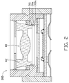
- FIG. 2 is a cross sectional view of an imaging module, according to a second exemplary embodiment of the present disclosure.
- the imaging module 100 includes a substrate 10 , an image sensor 20 , a lens barrel 30 , a lens 40 , and a holder 50 .
- the image sensor 20 is fixed on the substrate 10 .
- the lens 40 is received in the lens barrel 30 .
- the substrate 10 is fixed on an end of the lens barrel 30 .
- the lens barrel 30 is partially inserted into the holder 50 .
- the substrate 10 includes a first surface 11 and a second surface 12 at opposite sides thereof.
- the substrate 10 includes a plurality of first soldering pads 111 formed on the first surface 11 , and a plurality of first connecting portions 121 formed on the second surface 12 .
- Each first soldering pad 111 is electrically connected to a corresponding first connecting portion 121 .
- the image sensor 20 is fixed on the first surface 11 .
- the image sensor 20 includes a plurality of second soldering pads 21 each connected to one first soldering pad 111 using one wire 22 .
- the lens barrel 30 is connected to the substrate 10 to enclose the image sensor 20 .
- the lens barrel 30 defines a receiving hole 301 passing through the lens barrel 30 from an object end 33 to an image end 34 of the lens barrel 30 .
- the lens barrel 30 includes an inner side surface 35 surrounding the receiving hole 301 , the inner side surface 35 is an interface between the lens barrel 30 and the receiving hole 301 .
- the lens barrel 30 includes a protruding portion 31 positioned in the receiving hole 301 , the protruding portion 31 is formed on the inner side surface 35 and protrudes from the inner side surface 35 to an optical axis O-O of the imaging module 100 .
- the protruding portion 31 is elastic and can be elastically deformed relative to the inner side surface 35 of the lens barrel 30 .
- the protruding portion 31 is made of rubber.
- the protruding portion 31 can be annular.
- the lens barrel 30 defines a groove 32 in an outer side surface 36 thereof. In one embodiment, the groove 32 can be annular.
- the lens 40 includes a central optical portion 41 , and a supporting portion 42 around the optical portion 41 .
- the optical portion 41 is formed as a convex lens for converging passing light.
- the supporting portion 42 is integrally connected to the optical portion 41 to support the optical portion 41 in the lens barrel 30 . That is, the optical portion 41 and the supporting portion 42 are portions of a single, one-piece, monolithic body that is the lens 40 .
- the supporting portion 42 includes a planar object side surface 421 close to an object side of the imaging module 100 and a planar image side surface 422 close to an image side of the imaging module 100 . A size of the object side surface 421 is larger than that of the image side surface 422 .
- the outside diameter of the supporting portion 42 gradually reduces from the object side to the image side of the image module 100 .
- a part of the supporting portion 42 near the image side of the imaging module 100 is inserted into the protruding portion 31 of the lens barrel 30 .
- the inserting distance of the supporting portion 42 is determined by the inserting (pressing) force applied on the lens 40 . Therefore, a fixing position of the lens 40 can be adjusted by adjusting the pressing force.
- the adhesive 90 is located on an annular path around the outer surface of the supporting portion 42 , and interconnects the supporting portion 42 , a top wall of the protruding portion 31 , and an adjacent part of the inner surface of the lens barrel 30 .
- the holder 50 includes a peripheral side wall 51 , and a number of connecting members 52 fixed on the side wall 51 .
- the side wall 51 partially receives the lens barrel 30 .
- the side wall 51 includes an engaging portion 511 on an inner surface corresponding to the groove 32 of the lens barrel 30 .
- the engaging portion 511 can be annular.
- the connecting members 52 includes a third soldering pad 521 and a second connecting portion 522 .
- the third soldering pad 521 is fixed on an end of the side wall 51 .
- each of the second connecting portions 522 includes a contacting section 522 a in contact with the corresponding first connecting portion 121 .
- the contacting section 522 a resiliently abuts against the corresponding first connecting portion 121 .
- the second connecting portions 522 can be jointed to the corresponding first connecting portions 121 via solder.
- the imaging module 100 further includes an infrared filter 60 , a first shielding member 70 , and a second shielding member 80 .
- the infrared filter 60 is fixed in the lens barrel 30 between the first shielding member 70 and the image sensor 20 .
- the first shielding member 70 is fixed in the lens barrel 30 between the infrared filter 60 and the lens 40 .
- the second shielding member 80 is attached to an end of the lens 40 near the object side of the imaging module 100 . In one embodiment, the second shielding member 80 is attached and supported on the object side surface 421 of the supporting portion 40 .
- the infrared filter 60 is configured to keep infrared light from reaching the image sensor 20 .
- the first shielding member 70 and the second shielding member 80 are configured for keeping undesired visible light from reaching the image sensor 20 .
- the infrared filter 60 , the first shielding member 70 and the second shielding member 80 are fixed in the lens barrel 30 by glue (not labeled).
- a protruding portion 31 a includes an elastic adjusting section 311 .
- the elastic adjusting section 311 is generally a hollow, circular truncated cone in shape.
- the inside diameter of the adjusting section 311 gradually reduces from the object side to the image side of the imaging module 200 , and an end of the adjusting section 311 nearest the object side of the imaging module 200 is integrally connected with the protruding portion 31 a . That is, the protruding portion 31 a is a single, one-piece, monolithic body that includes the adjusting section 311 .
- the adjusting section 311 defines a number of adjusting grooves 311 a in an inner surface thereof.
- the adjusting grooves 311 a are annular.
- the supporting portion 42 of the lens 40 is inserted into the adjusting section 311 , and an inserted end of the supporting portion 42 is engaged in one of the adjusting grooves 311 a .
- a position of the lens 40 can be adjusted by engaging the inserted end of the supporting portion 42 in a selected one of the different adjusting grooves 311 a.
Landscapes
- Physics & Mathematics (AREA)
- General Physics & Mathematics (AREA)
- Optics & Photonics (AREA)
- Engineering & Computer Science (AREA)
- Multimedia (AREA)
- Signal Processing (AREA)
- Lens Barrels (AREA)
- Studio Devices (AREA)
Abstract
Description
Claims (18)
Applications Claiming Priority (3)
Application Number | Priority Date | Filing Date | Title |
---|---|---|---|
CN200910308015.3 | 2009-09-30 | ||
CN200910308015 | 2009-09-30 | ||
CN2009103080153A CN102036004B (en) | 2009-09-30 | 2009-09-30 | Imaging module |
Publications (2)
Publication Number | Publication Date |
---|---|
US20110075021A1 US20110075021A1 (en) | 2011-03-31 |
US8773572B2 true US8773572B2 (en) | 2014-07-08 |
Family
ID=43779952
Family Applications (1)
Application Number | Title | Priority Date | Filing Date |
---|---|---|---|
US12/756,121 Expired - Fee Related US8773572B2 (en) | 2009-09-30 | 2010-04-07 | Optical imaging module with fixed-focus lens |
Country Status (2)
Country | Link |
---|---|
US (1) | US8773572B2 (en) |
CN (1) | CN102036004B (en) |
Cited By (2)
Publication number | Priority date | Publication date | Assignee | Title |
---|---|---|---|---|
US20140132815A1 (en) * | 2014-01-27 | 2014-05-15 | Meizhou XiuYing Enterprise Company Limited | Digital camera structure capable of selectively mounting a camera lens |
US20230209161A1 (en) * | 2021-12-27 | 2023-06-29 | Samsung Electro-Mechanics Co., Ltd. | Camera module |
Families Citing this family (22)
Publication number | Priority date | Publication date | Assignee | Title |
---|---|---|---|---|
DE102012206252A1 (en) * | 2012-04-17 | 2013-10-17 | Robert Bosch Gmbh | Camera module and method of making a camera module |
US9307128B2 (en) * | 2012-06-26 | 2016-04-05 | Alex Ning | Lens mount |
KR20140140260A (en) * | 2013-05-29 | 2014-12-09 | 삼성전기주식회사 | Camera module |
CN105182493A (en) * | 2015-08-04 | 2015-12-23 | 南昌欧菲光电技术有限公司 | Camera module and support structure thereof |
CN105445888B (en) | 2015-12-21 | 2020-04-03 | 宁波舜宇光电信息有限公司 | Adjustable optical lens, camera module and calibration method thereof |
CN105445885B (en) * | 2015-10-30 | 2019-06-18 | 宁波舜宇光电信息有限公司 | Adjustable optical camera lens and camera module and its manufacturing method |
CN105372771B (en) * | 2015-12-16 | 2018-10-19 | 武汉优信技术股份有限公司 | A kind of optical module optical interface assemblies with collimation lens |
CN105812641A (en) * | 2016-06-02 | 2016-07-27 | 信利光电股份有限公司 | Fixed-focus camera module and electronic equipment |
CN105898127A (en) * | 2016-06-02 | 2016-08-24 | 信利光电股份有限公司 | Fixed focal camera module and electronic apparatus |
TWI600928B (en) * | 2016-09-30 | 2017-10-01 | 光寶電子(廣州)有限公司 | Filter assembly and camera module having the same |
TWI647502B (en) * | 2016-12-12 | 2019-01-11 | 台灣東電化股份有限公司 | Lens assembly and photographic device using the same |
CN208999737U (en) | 2017-10-19 | 2019-06-18 | 台湾东电化股份有限公司 | Optical drive mechanism |
WO2019150551A1 (en) | 2018-02-02 | 2019-08-08 | 富士通フロンテック株式会社 | Image pickup device |
KR102486426B1 (en) * | 2018-02-23 | 2023-01-09 | 엘지이노텍 주식회사 | Camera module |
CN110837165A (en) * | 2018-08-16 | 2020-02-25 | 宁波舜宇车载光学技术有限公司 | Optical lens and assembling method thereof |
CN109270654A (en) * | 2018-11-28 | 2019-01-25 | 信利光电股份有限公司 | A kind of optical lens |
CN109358402A (en) * | 2018-12-17 | 2019-02-19 | 浙江舜宇光学有限公司 | Imaging lens |
CN209525508U (en) * | 2018-12-27 | 2019-10-22 | 瑞声科技(新加坡)有限公司 | Camera lens and electronic equipment with camera function |
WO2021000221A1 (en) * | 2019-07-01 | 2021-01-07 | 瑞声光学解决方案私人有限公司 | Lens module and electronic apparatus |
US10942329B1 (en) * | 2019-09-23 | 2021-03-09 | Taiwan Semiconductor Manufacturing Company Ltd. | Optical module structure |
CN113960732A (en) * | 2020-07-16 | 2022-01-21 | Oppo广东移动通信有限公司 | Lens barrel, camera module, electronic device and lens barrel processing method |
WO2022051997A1 (en) * | 2020-09-10 | 2022-03-17 | 欧菲光集团股份有限公司 | Lens barrel, lens, and lens barrel manufacturing mold |
Citations (11)
Publication number | Priority date | Publication date | Assignee | Title |
---|---|---|---|---|
US20010050717A1 (en) * | 2000-06-12 | 2001-12-13 | Mitsubishi Denki Kabushiki Kaisha | Semiconductor device constituting a CMOS camera system |
US20020131782A1 (en) * | 2001-01-12 | 2002-09-19 | Susumu Yamaguchi | Image pickup device and image pickup lens |
US6734419B1 (en) * | 2001-06-28 | 2004-05-11 | Amkor Technology, Inc. | Method for forming an image sensor package with vision die in lens housing |
US20050141106A1 (en) * | 2003-12-31 | 2005-06-30 | Hyun-Ju Lee | Lens holder apparatus of camera lens module |
US20060202293A1 (en) * | 2003-09-26 | 2006-09-14 | Danut Bogdan | Optical module and optical system |
US20060215053A1 (en) * | 2005-03-22 | 2006-09-28 | Sharp Kabushiki Kaisha | Lens-position controller and imaging module |
CN1842139A (en) | 2005-03-31 | 2006-10-04 | 夏普株式会社 | Optical device module |
US20070120213A1 (en) * | 2005-11-28 | 2007-05-31 | Hiew Siew S | Wire under dam package and method for packaging image-sensor |
US20080267603A1 (en) * | 2007-04-26 | 2008-10-30 | Samsung Electro-Mechanics Co., Ltd. | Auto-focusing camera module having liquid lens |
US20080265134A1 (en) * | 2007-04-27 | 2008-10-30 | Sharp Kabushiki Kaisha | Optical unit, solid-state image sensing device and electronic apparatus comprising same |
US20080278621A1 (en) * | 2007-05-10 | 2008-11-13 | Samsung Electro-Mechanics Co., Ltd. | Camera module |
Family Cites Families (3)
Publication number | Priority date | Publication date | Assignee | Title |
---|---|---|---|---|
KR100571779B1 (en) * | 2003-11-27 | 2006-04-18 | 삼성전자주식회사 | An apparatus for controlling a project-lens of a projector to shift |
CN1744210A (en) * | 2004-09-01 | 2006-03-08 | 上海乐金广电电子有限公司 | Optical pick-up device regulator |
JP2008287784A (en) * | 2007-05-16 | 2008-11-27 | Sharp Corp | Optical pickup device |
-
2009
- 2009-09-30 CN CN2009103080153A patent/CN102036004B/en not_active Expired - Fee Related
-
2010
- 2010-04-07 US US12/756,121 patent/US8773572B2/en not_active Expired - Fee Related
Patent Citations (12)
Publication number | Priority date | Publication date | Assignee | Title |
---|---|---|---|---|
US20010050717A1 (en) * | 2000-06-12 | 2001-12-13 | Mitsubishi Denki Kabushiki Kaisha | Semiconductor device constituting a CMOS camera system |
US20020131782A1 (en) * | 2001-01-12 | 2002-09-19 | Susumu Yamaguchi | Image pickup device and image pickup lens |
US6734419B1 (en) * | 2001-06-28 | 2004-05-11 | Amkor Technology, Inc. | Method for forming an image sensor package with vision die in lens housing |
US20060202293A1 (en) * | 2003-09-26 | 2006-09-14 | Danut Bogdan | Optical module and optical system |
US20050141106A1 (en) * | 2003-12-31 | 2005-06-30 | Hyun-Ju Lee | Lens holder apparatus of camera lens module |
US20060215053A1 (en) * | 2005-03-22 | 2006-09-28 | Sharp Kabushiki Kaisha | Lens-position controller and imaging module |
CN1842139A (en) | 2005-03-31 | 2006-10-04 | 夏普株式会社 | Optical device module |
US20060219885A1 (en) * | 2005-03-31 | 2006-10-05 | Sharp Kabushiki Kaisha | Optical device module |
US20070120213A1 (en) * | 2005-11-28 | 2007-05-31 | Hiew Siew S | Wire under dam package and method for packaging image-sensor |
US20080267603A1 (en) * | 2007-04-26 | 2008-10-30 | Samsung Electro-Mechanics Co., Ltd. | Auto-focusing camera module having liquid lens |
US20080265134A1 (en) * | 2007-04-27 | 2008-10-30 | Sharp Kabushiki Kaisha | Optical unit, solid-state image sensing device and electronic apparatus comprising same |
US20080278621A1 (en) * | 2007-05-10 | 2008-11-13 | Samsung Electro-Mechanics Co., Ltd. | Camera module |
Cited By (3)
Publication number | Priority date | Publication date | Assignee | Title |
---|---|---|---|---|
US20140132815A1 (en) * | 2014-01-27 | 2014-05-15 | Meizhou XiuYing Enterprise Company Limited | Digital camera structure capable of selectively mounting a camera lens |
US20230209161A1 (en) * | 2021-12-27 | 2023-06-29 | Samsung Electro-Mechanics Co., Ltd. | Camera module |
US12063428B2 (en) * | 2021-12-27 | 2024-08-13 | Samsung Electro-Mechanics Co., Ltd. | Camera module |
Also Published As
Publication number | Publication date |
---|---|
US20110075021A1 (en) | 2011-03-31 |
CN102036004A (en) | 2011-04-27 |
CN102036004B (en) | 2013-07-03 |
Similar Documents
Publication | Publication Date | Title |
---|---|---|
US8773572B2 (en) | Optical imaging module with fixed-focus lens | |
US7729606B2 (en) | Lens module and digital camera module using same | |
US20240171842A1 (en) | Integrated image sensor and lens assembly | |
WO2011024387A1 (en) | Lens tube, image pickup device, and portable terminal apparatus | |
US8558938B2 (en) | Camera module and manufacturing method thereof | |
US7738196B2 (en) | Optical unit | |
US8436937B2 (en) | Camera module having socket with protrusion and method for assembling the same | |
CN112649938B (en) | Imaging lens, camera module and electronic device | |
JP2010191345A (en) | Lens unit, camera module, and method for manufacturing lens unit | |
JP2009526268A (en) | Integrated lens system for image sensor and manufacturing method thereof | |
US20090135297A1 (en) | Camera module | |
US5533159A (en) | Module for optical fiber communication | |
US20090096047A1 (en) | Imaging module package | |
JP4061936B2 (en) | Imaging device | |
US9810854B2 (en) | Optical fiber holding component, receptacle-equipped pigtail, patch cord, and optical module | |
JP2010219713A (en) | Imaging device | |
JPWO2018061295A1 (en) | Optical equipment and camera module | |
US7969669B1 (en) | Lens module | |
JP2008039895A (en) | Lens unit | |
KR101628296B1 (en) | Camera module | |
JP2008122636A (en) | Camera module | |
CN102595046A (en) | Focus-free camera module | |
KR20050000722A (en) | Small camera optical system | |
KR100854748B1 (en) | Camera module | |
KR20100083924A (en) | Camera module |
Legal Events
Date | Code | Title | Description |
---|---|---|---|
AS | Assignment |
Owner name: HON HAI PRECISION INDUSTRY CO., LTD., TAIWAN Free format text: ASSIGNMENT OF ASSIGNORS INTEREST;ASSIGNOR:CHANG, JEN-TSORNG;REEL/FRAME:024201/0677 Effective date: 20100401 |
|
FEPP | Fee payment procedure |
Free format text: MAINTENANCE FEE REMINDER MAILED (ORIGINAL EVENT CODE: REM.) |
|
LAPS | Lapse for failure to pay maintenance fees |
Free format text: PATENT EXPIRED FOR FAILURE TO PAY MAINTENANCE FEES (ORIGINAL EVENT CODE: EXP.) |
|
STCH | Information on status: patent discontinuation |
Free format text: PATENT EXPIRED DUE TO NONPAYMENT OF MAINTENANCE FEES UNDER 37 CFR 1.362 |
|
FP | Lapsed due to failure to pay maintenance fee |
Effective date: 20180708 |