US8771900B2 - Super-hydrophobic composite bipolar plate including a porous surface layer - Google Patents
Super-hydrophobic composite bipolar plate including a porous surface layer Download PDFInfo
- Publication number
- US8771900B2 US8771900B2 US12/841,813 US84181310A US8771900B2 US 8771900 B2 US8771900 B2 US 8771900B2 US 84181310 A US84181310 A US 84181310A US 8771900 B2 US8771900 B2 US 8771900B2
- Authority
- US
- United States
- Prior art keywords
- set forth
- substrate
- surface layer
- product
- porous surface
- Prior art date
- Legal status (The legal status is an assumption and is not a legal conclusion. Google has not performed a legal analysis and makes no representation as to the accuracy of the status listed.)
- Active, expires
Links
Images


Classifications
-
- H—ELECTRICITY
- H01—ELECTRIC ELEMENTS
- H01M—PROCESSES OR MEANS, e.g. BATTERIES, FOR THE DIRECT CONVERSION OF CHEMICAL ENERGY INTO ELECTRICAL ENERGY
- H01M8/00—Fuel cells; Manufacture thereof
- H01M8/02—Details
- H01M8/0202—Collectors; Separators, e.g. bipolar separators; Interconnectors
- H01M8/0204—Non-porous and characterised by the material
- H01M8/0223—Composites
- H01M8/0228—Composites in the form of layered or coated products
-
- H—ELECTRICITY
- H01—ELECTRIC ELEMENTS
- H01M—PROCESSES OR MEANS, e.g. BATTERIES, FOR THE DIRECT CONVERSION OF CHEMICAL ENERGY INTO ELECTRICAL ENERGY
- H01M8/00—Fuel cells; Manufacture thereof
- H01M8/02—Details
- H01M8/0202—Collectors; Separators, e.g. bipolar separators; Interconnectors
- H01M8/0204—Non-porous and characterised by the material
- H01M8/0206—Metals or alloys
-
- H—ELECTRICITY
- H01—ELECTRIC ELEMENTS
- H01M—PROCESSES OR MEANS, e.g. BATTERIES, FOR THE DIRECT CONVERSION OF CHEMICAL ENERGY INTO ELECTRICAL ENERGY
- H01M8/00—Fuel cells; Manufacture thereof
- H01M8/02—Details
- H01M8/0202—Collectors; Separators, e.g. bipolar separators; Interconnectors
- H01M8/023—Porous and characterised by the material
- H01M8/0234—Carbonaceous material
-
- Y—GENERAL TAGGING OF NEW TECHNOLOGICAL DEVELOPMENTS; GENERAL TAGGING OF CROSS-SECTIONAL TECHNOLOGIES SPANNING OVER SEVERAL SECTIONS OF THE IPC; TECHNICAL SUBJECTS COVERED BY FORMER USPC CROSS-REFERENCE ART COLLECTIONS [XRACs] AND DIGESTS
- Y02—TECHNOLOGIES OR APPLICATIONS FOR MITIGATION OR ADAPTATION AGAINST CLIMATE CHANGE
- Y02E—REDUCTION OF GREENHOUSE GAS [GHG] EMISSIONS, RELATED TO ENERGY GENERATION, TRANSMISSION OR DISTRIBUTION
- Y02E60/00—Enabling technologies; Technologies with a potential or indirect contribution to GHG emissions mitigation
- Y02E60/30—Hydrogen technology
- Y02E60/50—Fuel cells
Definitions
- This invention relates generally to a bipolar plate for a fuel cell and, more particularly, a bipolar plate for a fuel cell that includes a super-hydrophobic coating.
- a hydrogen fuel cell is an electro-chemical device that includes an anode and a cathode with an electrolyte therebetween.
- the anode receives hydrogen gas and the cathode receives oxygen or air.
- the hydrogen gas is dissociated in the anode to generate free protons and electrons.
- the protons pass through the electrolyte to the cathode.
- the protons react with the oxygen and the electrons in the cathode to generate water.
- the electrons from the anode cannot pass through the electrolyte, and thus are directed through a load to perform work before being sent to the cathode. The work acts to operate the vehicle.
- PEMFC Proton exchange membrane fuel cells
- the PEMFC generally includes a solid polymer-electrolyte proton-conducting membrane, such as a perfluorosulfonic acid membrane.
- the anode and cathode typically include finely divided catalytic particles, usually platinum (Pt), supported on carbon particles and mixed with an ionomer.
- the catalytic mixture is deposited on opposing sides of the membrane.
- the combination of the anode catalytic mixture, the cathode catalytic mixture and the membrane define a membrane electrode assembly (MEA).
- MEA membrane electrode assembly
- the stack may include two hundred or more fuel cells.
- the fuel cell stack receives a cathode reactant gas, typically a flow of air forced through the stack by a compressor. Not all of the oxygen is consumed by the stack and some of the air is output as a cathode exhaust gas that may include water as a stack by-product.
- the fuel cell stack also receives an anode hydrogen reactant gas that flows into the anode side of the stack.
- the fuel cell stack includes a series of bipolar plates positioned between the several MEAs in the stack, where the bipolar plates and the MEAs are positioned between two end plates.
- the bipolar plates include an anode side and a cathode side for adjacent fuel cells in the stack.
- Anode gas flow channels are provided on the anode side of the bipolar plates that allow the anode reactant gas to flow to the respective MEA.
- Cathode gas flow channels are provided on the cathode side of the bipolar plates that allow the cathode reactant gas to flow to the respective MEA.
- One end plate includes anode gas flow channels, and the other end plate includes cathode gas flow channels.
- the bipolar plates and end plates are made of a conductive material, such as stainless steel or a conductive composite. The end plates conduct the electricity generated by the fuel cells out of the stack.
- the bipolar plates are typically made of a conductive material, such as stainless steel, titanium, aluminum, polymeric carbon composites, etc., so that they conduct the electricity generated by the fuel cells from one cell to the next cell and out of the stack.
- Metal bipolar plates typically produce a natural oxide on their outer surface that makes them resistant to corrosion. However, the oxide layer is not conductive, and thus increases the internal resistance of the fuel cell, reducing its electrical performance. It is known in the art to deposit a thin layer of a conductive material, such as gold, on the bipolar plates to reduce the contact resistance between the plate and diffusion media in the fuel cells.
- the membranes within a fuel cell need to have a certain relative humidity so that the ionic resistance across the membrane is low enough to effectively conduct protons.
- moisture from the MEAs and external humidification may enter the anode and cathode flow channels.
- the water may accumulate within the flow channels because the flow rate of the reactant gas is too low to force the water out of the channels.
- the water forms droplets that continue to expand because of the relatively hydrophobic nature of the plate material. The droplets form in the flow channels substantially perpendicular to the flow of the reactant gas.
- the flow channel is closed off, and the reactant gas is diverted to other flow channels because the channels are in parallel between common inlet and outlet manifolds. Because the reactant gas may not flow through a channel that is blocked with water, the reactant gas cannot force the water out of the channel. Those areas of the membrane that do not receive reactant gas as a result of the channel being blocked will not generate electricity, thus resulting in a non-homogenous current distribution and reducing the overall efficiency of the fuel cell. As more and more flow channels are blocked by water, the electricity produced by the fuel cell decreases, where a cell voltage potential less than 200 mV is considered a cell failure. Because the fuel cells are electrically coupled in series, if one of the fuel cells stops performing, the entire fuel cell stack may stop performing.
- Reducing accumulated water in the channels can also be accomplished by reducing inlet humidification.
- a dry inlet gas has a drying effect on the membrane that could increase the cell's ionic resistance, and limit the membrane's long-term durability.
- a hydrophilic plate causes water in the channels to form a thin film that has less of a tendency to alter the flow distribution along the array of channels connected to the common inlet and outlet headers. If the plate material is sufficiently wettable, water transport through the diffusion media will contact the channel walls and then, by capillary force, be transported into the bottom corners of the channel along its length.
- the physical requirements to support spontaneous wetting in the corners of a flow channel are described by the Concus-Finn condition,
- Hydrophilic treatments of bipolar plates may be suitable for inducing capillary flows in fine-pitched flow fields. However, it may be desirable to provide hydrophobic surfaces for other bipolar plate designs, for example, in flow field designs with wider channels and/or if external contamination is found to contaminate hydrophilic surfaces because the hydrophobic surfaces are less prone to contamination than are hydrophilic surfaces. In addition, a hydrophobic bipolar plate is desired from an electrochemical and chemical durability standpoint.
- Water and water-containing hydrogen ions and fluoride ions i.e., hydrofluoric acid observed from degradation of the perfluorosulfonic acid membrane materials, will have a high contact angle and not wet out the hydrophobic plate surface, thereby reducing the rate of chemical and electro-chemical degradation of composite and stainless steel plates, respectively. More importantly, because of the high contact angle exhibited by water droplets on hydrophobic surfaces, lower reactant gas velocities are required to force the droplets out of the channels, thereby enabling the gases to effectively react in the electrodes. Lower gas velocities result in a reduction of compressor parasitic losses and in an increase in hydrogen gas utilization.
- One embodiment of the invention includes a product including a fuel cell component having a porous layer comprising silicon, oxygen and carbon, where the porous layer is super-hydrophobic having a contact angle of greater than 130°.
- Another embodiment of the invention includes a fuel cell bipolar plate including a composite substrate comprising carbon, and a porous layer comprising silicon, oxygen and carbon, where the porous layer is super-hydrophobic having a contact angle greater than 130°.
- Another embodiment of the invention includes a bipolar plate comprising a substrate, a first layer over the substrate comprising carbon, a porous layer over the first layer, where the porous layer comprises silicon, oxygen and carbon, and where the porous layer has a contact angle greater than 130°.
- Another embodiment of the invention includes a method for making a super-hydrophobic bipolar plate including providing a substrate including carbon, and a porous layer over the substrate, where the porous layer includes silicon and oxygen.
- the method includes causing the carbon in the substrate to diffuse outwardly through the porous layer and attaching to at least one of the silicon or oxygen.
- Another embodiment of the invention includes a method for making a super-hydrophobic composite bipolar plate including providing a substrate comprising a composite material including carbon, and a porous layer on the substrate, where the porous layer includes silicon and oxygen.
- the method includes heating the substrate and surface layer to cause moieties including carbon from the substrate to diffuse outwardly through the porous layer and so that the moiety is attached to one of the silicon or oxygen.
- FIG. 1 illustrates one embodiment of the invention that includes making a super-hydrophobic fuel cell component including heating a substrate including carbon to diffuse the carbon into an overlying porous layer that includes silicon and oxygen so that the carbon attaches to at least one of the silicon and oxygen.
- FIG. 2 illustrates another embodiment of the invention that includes making a super-hydrophobic fuel cell component including selectively heating portions of a substrate including carbon so that carbon diffuses through an overlying porous layer including silicon and oxygen and so that the carbon attaches to at least one of the silicon or oxygen in selective regions of the porous layer.
- FIG. 3 illustrates another embodiment of the invention that includes making a super-hydrophobic fuel cell component including providing a substrate including carbon and a porous layer selectively deposited over portions of the substrate and selectively heating portions of the substrate so that carbon diffuses into the porous layer and attaches to at least one of the silicon or oxygen.
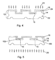
- FIG. 4 illustrates another embodiment of the invention that includes making a super-hydrophobic fuel cell component including providing a first substrate and a first layer including carbon over the first substrate and a porous layer including silicon and oxygen over the first layer, and heating the first substrate, first layer and porous layer so that carbon from the first layer diffuses into the porous layer and attaches to at least one of the silicon or oxygen therein.
- FIG. 5 illustrates another embodiment of the invention that includes making a super-hydrophobic fuel cell component including a first substrate having an upper surface and depositing a diffusion barrier material over selected portions of the upper surface of the substrate leaving portions of the upper surface exposed, where the substrate comprises a hydrocarbon material, and depositing a porous layer comprising silicon and oxygen over the diffusion barrier material and the exposed portions of the upper surface of the substrate and heating the substrate so that hydrocarbon moieties diffuse from the substrate into the porous layer in portions of the porous layer that overlie the exposed portions of the upper surface of the substrate.
- FIG. 6 is a graphic illustration of a SIMS analysis of the surface composition of a composite bipolar plate having a siloxane coating thereon that has not been heated.
- FIG. 7 is a graphic illustration of a SIMS analysis of the surface composition of a composite bipolar plate having a siloxane coating thereon that has been heated.
- FIG. 1 illustrates a method for making a fuel cell component 10 including a substrate 12 which may, for example, be a composite bipolar plate including a carbon containing material such as graphite, according to an embodiment of the present invention.
- the substrate 12 may include a plurality of lands 14 and channels 16 to form a gas flow field useful in a fuel cell.
- a porous surface layer 18 is deposited over the lands 14 and channels 16 of the substrate 12 .
- the surface layer 18 may be deposited by any suitable process, such as chemical vapor deposition (CVD), physical vapor deposition (PVD), dipping, spraying, etc.
- CVD chemical vapor deposition
- PVD physical vapor deposition
- the porous surface layer 18 may include silicon and oxygen, such as for example, silicon dioxide, siloxane, a siloxane derived material or a material including SiO x , where 0.1 ⁇ x ⁇ 2.0.
- carbon material such as hydrocarbon moieties from the substrate 12 , is diffused through the porous surface layer 18 and attached to at least one of the silicon and oxygen.
- the substrate 12 is heated to a temperature ranging from 90° C. to 200° C. for 10 to 90 minutes by heat radiation on 20 to cause the hydrocarbon moieties to diffuse outwardly from the substrate 12 and into and through the porous surface layer 18 .
- the hydrocarbon moieties attached to one of the silicon and/or oxygen creates a super-hydrophobic surface having a contact angle greater than 130°.
- the heat radiation 20 can be any heat radiation suitable for the purposes described herein. Suitable examples include electron beam or laser beam heating. Laser beam heating may present certain concerns because of the localized heating required in that the composite plate materials typically have a high thermal conductivity, and thus, temperature gradings could be produced. When using a laser beam for the heat radiation 20 , it may be desirable to only heat the channels, and not the lands, of the plates so that the channels can become hydrophobic and thereby facilitate channel water removal.
- Hydrocarbons and composite plates include non-reactant monomers and oligomers, such as styrene, vinyl esther, phenols, esthers, epoxy, amines, etc., internal low-molecular weight processing additives and internal mold release agents. Hydrocarbons in the carbon coating on metal plates also includes these non-reactant monomers and oligomers as well as residual solvents used in the coating application.
- the heat radiation 20 is applied to selective areas of the substrate 12 , such as only over the lands 14 so that hydrocarbon moieties are diffused through the porous layer only in the areas near the lands 14 .
- a diffusion barrier material 100 may be selectively deposited over the substrate 12 , for example in the area of the channel 16 , so that hydrocarbon moieties are prevented from diffusing into the porous layer 18 in the area where the diffusion barrier material 100 is provided.
- the diffusion barrier material 100 may be selectively deposited using masking techniques or by selectively removing portions of a diffusion barrier material 100 deposited over the upper surface of the substrate 12 , for example, by removing portions of the diffusion barrier material 100 deposited over the lands 14 . Consequently, super-hydrophobic surfaces are selectively formed on the porous layer 18 , for example, only over the lands 14 .
- the porous layer 18 may be selectively deposited, for example, only over the lands 14 and heat applied directed only to the area of the lands 14 of the substrate.
- FIG. 4 illustrates another embodiment of the invention where the substrate 12 includes a base material 22 such as a metal, for example, stainless steel, and a first layer 24 overlying the base material 22 .
- the first layer 24 includes a carbon material, such as graphite.
- the first layer 24 consists of carbon black and/or graphite particles mixed with an organic resin, such as polymide imide, phenolic, epoxy, etc.
- a porous layer 18 is provided over the first layer 24 and hydrocarbon moieties are diffused through the porous layer 18 , for example, by applying heat to the substrate 12 so that the hydrocarbon moiety is attached to at least one of silicon and/or oxygen in the porous layer 18 to create super-hydrophobic surfaces having a contact angle greater than 130°.
- the diffusion of hydrocarbon moieties from the substrate 12 into the porous layer 18 may be accomplished, for example, by heating the substrate 12 in an oven, or on a hot plate, with a laser beam or electron beam, or by hot pressing portions of the porous layer 18
- Table I presents contact angle results as a function of 175° C. oven exposure time for various composite plate materials coated with PlasmaTech Inc. SiO x coating ( ⁇ 80 nm thick) via a plasma enhanced chemical vapor deposition process. The samples were wrapped in aluminum foil in the oven to eliminate external contamination effects. Contact angle measurements were made at 21° C. using the Kruss DSA 10 Mk2 drop analyzer and a 10 ⁇ l DI-water drop volume. Except for material D, the carbon coating typically consists of carbon black and/or graphite particles, mixed with an organic resin, such as polymide imide, phenolic, epoxy, etc. The contact angles for all of the composite materials increased to super-hydrophobic levels within 30 minutes. Note that the uncoated VE and NBO B samples did not increase in phobicity with 175 C oven exposures, indicating that a silica philic layer is required.
- FIG. 6 is a graphic illustration of a SIMS analysis of the surface composition of a composite bipolar plate having a silica coating thereon that has not been heated.
- FIG. 7 is a graphic illustration of a SIMS analysis of the surface composition of a composite bipolar plate having a silica coating thereon that has not been heated.
- the porous layer 18 includes hydrocarbon moieties attached to at least one of the silicon or oxygen therein (atomic mass units of 27, 41 and 43). Fragments identified in the SIMS analysis were as follows:
Landscapes
- Chemical & Material Sciences (AREA)
- Life Sciences & Earth Sciences (AREA)
- Engineering & Computer Science (AREA)
- Manufacturing & Machinery (AREA)
- Sustainable Development (AREA)
- Sustainable Energy (AREA)
- Chemical Kinetics & Catalysis (AREA)
- Electrochemistry (AREA)
- General Chemical & Material Sciences (AREA)
- Composite Materials (AREA)
- Fuel Cell (AREA)
Abstract
Description
where β is the static contact angle and α is the channel corner angle. For a rectangular channel α/2=45°, which dictates that spontaneous wetting will occur when the static contact angle is less than 45°. For the roughly rectangular channels used in current fuel cell stack designs, this sets an approximate upper limit on the contact angle needed to realize the beneficial effects of hydrophilic plate surfaces on channel water transport and low load stability.
| TABLE I | ||||||||
| VE | NBO B | |||||||
| time | (no | (no | ||||||
| (hr) | SiOx) | VE | SiOx) | NBO B | S | | NBO C2 | |
| 0 | 76.13 | <10 | 81.22 | <10 | <10 | <10 | <10 |
| 0.5 | 75.26 | 68.4 | 80.22 | 139.21 | 154.89 | ~13 | 139 |
| 1 | 76.96 | 121.5 | 79.85 | 139.11 | 139 | 43.9 | 146.8 |
| 54 | 74 | 135.67 | 81.25 | 150.98 | 130.77 | 10-60 | 153.69 |
| non- | |||||||
| uniform | |||||||
Claims (18)
Priority Applications (1)
| Application Number | Priority Date | Filing Date | Title |
|---|---|---|---|
| US12/841,813 US8771900B2 (en) | 2006-10-31 | 2010-07-22 | Super-hydrophobic composite bipolar plate including a porous surface layer |
Applications Claiming Priority (2)
| Application Number | Priority Date | Filing Date | Title |
|---|---|---|---|
| US11/590,284 US7803499B2 (en) | 2006-10-31 | 2006-10-31 | Super-hydrophobic composite bipolar plate |
| US12/841,813 US8771900B2 (en) | 2006-10-31 | 2010-07-22 | Super-hydrophobic composite bipolar plate including a porous surface layer |
Related Parent Applications (1)
| Application Number | Title | Priority Date | Filing Date |
|---|---|---|---|
| US11/590,284 Division US7803499B2 (en) | 2006-10-31 | 2006-10-31 | Super-hydrophobic composite bipolar plate |
Publications (2)
| Publication Number | Publication Date |
|---|---|
| US20120021336A1 US20120021336A1 (en) | 2012-01-26 |
| US8771900B2 true US8771900B2 (en) | 2014-07-08 |
Family
ID=45493900
Family Applications (1)
| Application Number | Title | Priority Date | Filing Date |
|---|---|---|---|
| US12/841,813 Active 2029-02-05 US8771900B2 (en) | 2006-10-31 | 2010-07-22 | Super-hydrophobic composite bipolar plate including a porous surface layer |
Country Status (1)
| Country | Link |
|---|---|
| US (1) | US8771900B2 (en) |
Families Citing this family (1)
| Publication number | Priority date | Publication date | Assignee | Title |
|---|---|---|---|---|
| US10388916B2 (en) * | 2015-09-18 | 2019-08-20 | Gs Yuasa International Ltd. | Energy storage apparatus |
Citations (9)
| Publication number | Priority date | Publication date | Assignee | Title |
|---|---|---|---|---|
| US4943496A (en) | 1988-01-25 | 1990-07-24 | Hitachi, Ltd. | Fuel cell, electrode for the cell and method of preparation thereof |
| US5618392A (en) * | 1991-10-31 | 1997-04-08 | Tanaka Kikinzoku Kogyo K.K. | Gas diffusion electrode |
| US5998058A (en) | 1998-04-29 | 1999-12-07 | International Fuel Cells Corporation | Porous support layer for an electrochemical cell |
| US20030054221A1 (en) * | 1998-02-06 | 2003-03-20 | Kazuo Saito | Fuel cell separator and process for producing the same |
| WO2003047016A2 (en) | 2001-11-30 | 2003-06-05 | Schunk Kohlenstofftechnik Gmbh | Bipolar plate, press device and method for production thereof |
| US20030157391A1 (en) * | 2002-02-05 | 2003-08-21 | Gencell Corporation | Silane coated metallic fuel cell components and methods of manufacture |
| WO2005117176A2 (en) | 2004-05-24 | 2005-12-08 | Universita' Degli Studi Di Milano - Bicocca | Method for making components for fuel cells and fuel cells made thereby |
| US20060093735A1 (en) | 2004-11-01 | 2006-05-04 | Yang-Tse Cheng | Fuel cell water management enhancement method |
| US20080102347A1 (en) * | 2006-10-31 | 2008-05-01 | Gm Global Technology Operations, Inc. | Super-hydrophobic composite bipolar plate |
-
2010
- 2010-07-22 US US12/841,813 patent/US8771900B2/en active Active
Patent Citations (9)
| Publication number | Priority date | Publication date | Assignee | Title |
|---|---|---|---|---|
| US4943496A (en) | 1988-01-25 | 1990-07-24 | Hitachi, Ltd. | Fuel cell, electrode for the cell and method of preparation thereof |
| US5618392A (en) * | 1991-10-31 | 1997-04-08 | Tanaka Kikinzoku Kogyo K.K. | Gas diffusion electrode |
| US20030054221A1 (en) * | 1998-02-06 | 2003-03-20 | Kazuo Saito | Fuel cell separator and process for producing the same |
| US5998058A (en) | 1998-04-29 | 1999-12-07 | International Fuel Cells Corporation | Porous support layer for an electrochemical cell |
| WO2003047016A2 (en) | 2001-11-30 | 2003-06-05 | Schunk Kohlenstofftechnik Gmbh | Bipolar plate, press device and method for production thereof |
| US20030157391A1 (en) * | 2002-02-05 | 2003-08-21 | Gencell Corporation | Silane coated metallic fuel cell components and methods of manufacture |
| WO2005117176A2 (en) | 2004-05-24 | 2005-12-08 | Universita' Degli Studi Di Milano - Bicocca | Method for making components for fuel cells and fuel cells made thereby |
| US20060093735A1 (en) | 2004-11-01 | 2006-05-04 | Yang-Tse Cheng | Fuel cell water management enhancement method |
| US20080102347A1 (en) * | 2006-10-31 | 2008-05-01 | Gm Global Technology Operations, Inc. | Super-hydrophobic composite bipolar plate |
Also Published As
| Publication number | Publication date |
|---|---|
| US20120021336A1 (en) | 2012-01-26 |
Similar Documents
| Publication | Publication Date | Title |
|---|---|---|
| US7803499B2 (en) | Super-hydrophobic composite bipolar plate | |
| US9029046B2 (en) | Hydrophilic coating for fuel cell bipolar plate and methods of making the same | |
| US8470488B2 (en) | Metallic bipolar plates with high electrochemical stability and improved water management | |
| US8735022B2 (en) | Fuel cell component with coating including nanoparticles | |
| US7879389B2 (en) | Low-cost bipolar plate coatings for PEM fuel cell | |
| US7897295B2 (en) | Surface engineering of bipolar plate materials for better water management | |
| US20060216571A1 (en) | Metal oxide based hydrophilic coatings for PEM fuel cell bipolar plates | |
| US8389174B2 (en) | Super-hydrophilic nanoporous electrically conductive coatings for PEM fuel cells | |
| US8603703B2 (en) | Method for making super-hydrophilic and electrically conducting surfaces for fuel cell bipolar plates | |
| US7531100B2 (en) | Method of making a fuel cell component using an easily removed mask | |
| US20070287057A1 (en) | Method for making a hydrophilic corrosion resistant coating on low grade stainless steel/alloys for bipolar plates | |
| US20090191351A1 (en) | Fuel cell bipolar plate with variable surface properties | |
| US8323415B2 (en) | Fast recycling process for ruthenium, gold and titanium coatings from hydrophilic PEM fuel cell bipolar plates | |
| US8182884B2 (en) | Process for application of a hydrophilic coating to fuel cell bipolar plates | |
| US20060216570A1 (en) | Durable hydrophilic coatings for fuel cell bipolar plates | |
| US8771900B2 (en) | Super-hydrophobic composite bipolar plate including a porous surface layer | |
| US9281536B2 (en) | Material design to enable high mid-temperature performance of a fuel cell with ultrathin electrodes | |
| US8497049B2 (en) | Hydrophilic and corrosion resistant fuel cell components | |
| US8389047B2 (en) | Low-cost hydrophilic treatment method for assembled PEMFC stacks | |
| JP4970007B2 (en) | Water management of PEM fuel cell stacks using surfactants | |
| WO2007021688A2 (en) | Process for application of a hydrophilic coating to fuel cell bipolar plates | |
| US20070036890A1 (en) | Method of making a fuel cell component using a mask |
Legal Events
| Date | Code | Title | Description |
|---|---|---|---|
| AS | Assignment |
Owner name: WILMINGTON TRUST COMPANY, DELAWARE Free format text: SECURITY AGREEMENT;ASSIGNOR:GM GLOBAL TECHNOLOGY OPERATIONS, INC.;REEL/FRAME:025327/0156 Effective date: 20101027 |
|
| AS | Assignment |
Owner name: GM GLOBAL TECHNOLOGY OPERATIONS LLC, MICHIGAN Free format text: CHANGE OF NAME;ASSIGNOR:GM GLOBAL TECHNOLOGY OPERATIONS, INC.;REEL/FRAME:025781/0333 Effective date: 20101202 |
|
| FEPP | Fee payment procedure |
Free format text: PAYOR NUMBER ASSIGNED (ORIGINAL EVENT CODE: ASPN); ENTITY STATUS OF PATENT OWNER: LARGE ENTITY |
|
| STCF | Information on status: patent grant |
Free format text: PATENTED CASE |
|
| AS | Assignment |
Owner name: GM GLOBAL TECHNOLOGY OPERATIONS LLC, MICHIGAN Free format text: RELEASE BY SECURED PARTY;ASSIGNOR:WILMINGTON TRUST COMPANY;REEL/FRAME:034287/0159 Effective date: 20141017 |
|
| MAFP | Maintenance fee payment |
Free format text: PAYMENT OF MAINTENANCE FEE, 4TH YEAR, LARGE ENTITY (ORIGINAL EVENT CODE: M1551) Year of fee payment: 4 |
|
| MAFP | Maintenance fee payment |
Free format text: PAYMENT OF MAINTENANCE FEE, 8TH YEAR, LARGE ENTITY (ORIGINAL EVENT CODE: M1552); ENTITY STATUS OF PATENT OWNER: LARGE ENTITY Year of fee payment: 8 |
|
| FEPP | Fee payment procedure |
Free format text: MAINTENANCE FEE REMINDER MAILED (ORIGINAL EVENT CODE: REM.); ENTITY STATUS OF PATENT OWNER: LARGE ENTITY |