US8770646B2 - Adjustable floating seat - Google Patents

Adjustable floating seat Download PDF

Info

Publication number
US8770646B2
US8770646B2 US13/251,469 US201113251469A US8770646B2 US 8770646 B2 US8770646 B2 US 8770646B2 US 201113251469 A US201113251469 A US 201113251469A US 8770646 B2 US8770646 B2 US 8770646B2
Authority
US
United States
Prior art keywords
seat
vehicle
frame
brace
assembly
Prior art date
Legal status (The legal status is an assumption and is not a legal conclusion. Google has not performed a legal analysis and makes no representation as to the accuracy of the status listed.)
Expired - Fee Related, expires
Application number
US13/251,469
Other versions
US20130082478A1 (en
Inventor
Johnathan Andrew Line
Kendrick Alden Harper
John W. Jaranson
Michael John Kitti
Daniel Ferretti
Current Assignee (The listed assignees may be inaccurate. Google has not performed a legal analysis and makes no representation or warranty as to the accuracy of the list.)
Ford Global Technologies LLC
Original Assignee
Ford Global Technologies LLC
Priority date (The priority date is an assumption and is not a legal conclusion. Google has not performed a legal analysis and makes no representation as to the accuracy of the date listed.)
Filing date
Publication date
Application filed by Ford Global Technologies LLC filed Critical Ford Global Technologies LLC
Priority to US13/251,469 priority Critical patent/US8770646B2/en
Assigned to FORD GLOBAL TECHNOLOGIES, LLC reassignment FORD GLOBAL TECHNOLOGIES, LLC ASSIGNMENT OF ASSIGNORS INTEREST (SEE DOCUMENT FOR DETAILS). Assignors: HARPER, KENDRICK ALDEN, MR., KITTI, MICHAEL JOHN, MR., JARANSON, JOHN W., MR., FERRETTI, DANIEL, MR., LINE, JOHNATHAN ANDREW, MR.
Priority to CN201220472156.6U priority patent/CN202827207U/en
Publication of US20130082478A1 publication Critical patent/US20130082478A1/en
Application granted granted Critical
Publication of US8770646B2 publication Critical patent/US8770646B2/en
Expired - Fee Related legal-status Critical Current
Adjusted expiration legal-status Critical

Links

Images

Classifications

    • BPERFORMING OPERATIONS; TRANSPORTING
    • B60VEHICLES IN GENERAL
    • B60NSEATS SPECIALLY ADAPTED FOR VEHICLES; VEHICLE PASSENGER ACCOMMODATION NOT OTHERWISE PROVIDED FOR
    • B60N2/00Seats specially adapted for vehicles; Arrangement or mounting of seats in vehicles
    • B60N2/02Seats specially adapted for vehicles; Arrangement or mounting of seats in vehicles the seat or part thereof being movable, e.g. adjustable
    • B60N2/0224Non-manual adjustments, e.g. with electrical operation
    • B60N2/02246Electric motors therefor
    • B60N2/02258Electric motors therefor characterised by the mounting of the electric motor for adjusting the seat
    • BPERFORMING OPERATIONS; TRANSPORTING
    • B60VEHICLES IN GENERAL
    • B60NSEATS SPECIALLY ADAPTED FOR VEHICLES; VEHICLE PASSENGER ACCOMMODATION NOT OTHERWISE PROVIDED FOR
    • B60N2/00Seats specially adapted for vehicles; Arrangement or mounting of seats in vehicles
    • B60N2/02Seats specially adapted for vehicles; Arrangement or mounting of seats in vehicles the seat or part thereof being movable, e.g. adjustable
    • B60N2/04Seats specially adapted for vehicles; Arrangement or mounting of seats in vehicles the seat or part thereof being movable, e.g. adjustable the whole seat being movable
    • B60N2/06Seats specially adapted for vehicles; Arrangement or mounting of seats in vehicles the seat or part thereof being movable, e.g. adjustable the whole seat being movable slidable
    • B60N2/07Slide construction
    • B60N2/0735Position and orientation of the slide as a whole
    • B60N2/0747Position and orientation of the slide as a whole the opening of the cross section being oriented in a direction different from the vertical, e.g. transversal
    • BPERFORMING OPERATIONS; TRANSPORTING
    • B60VEHICLES IN GENERAL
    • B60NSEATS SPECIALLY ADAPTED FOR VEHICLES; VEHICLE PASSENGER ACCOMMODATION NOT OTHERWISE PROVIDED FOR
    • B60N2/00Seats specially adapted for vehicles; Arrangement or mounting of seats in vehicles
    • B60N2/02Seats specially adapted for vehicles; Arrangement or mounting of seats in vehicles the seat or part thereof being movable, e.g. adjustable
    • B60N2/04Seats specially adapted for vehicles; Arrangement or mounting of seats in vehicles the seat or part thereof being movable, e.g. adjustable the whole seat being movable
    • B60N2/16Seats specially adapted for vehicles; Arrangement or mounting of seats in vehicles the seat or part thereof being movable, e.g. adjustable the whole seat being movable height-adjustable
    • B60N2/1605Seats specially adapted for vehicles; Arrangement or mounting of seats in vehicles the seat or part thereof being movable, e.g. adjustable the whole seat being movable height-adjustable characterised by the cinematic
    • B60N2/161Rods
    • B60N2/1615Parallelogram-like structure
    • BPERFORMING OPERATIONS; TRANSPORTING
    • B60VEHICLES IN GENERAL
    • B60NSEATS SPECIALLY ADAPTED FOR VEHICLES; VEHICLE PASSENGER ACCOMMODATION NOT OTHERWISE PROVIDED FOR
    • B60N2/00Seats specially adapted for vehicles; Arrangement or mounting of seats in vehicles
    • B60N2/02Seats specially adapted for vehicles; Arrangement or mounting of seats in vehicles the seat or part thereof being movable, e.g. adjustable
    • B60N2/04Seats specially adapted for vehicles; Arrangement or mounting of seats in vehicles the seat or part thereof being movable, e.g. adjustable the whole seat being movable
    • B60N2/16Seats specially adapted for vehicles; Arrangement or mounting of seats in vehicles the seat or part thereof being movable, e.g. adjustable the whole seat being movable height-adjustable
    • B60N2/1635Seats specially adapted for vehicles; Arrangement or mounting of seats in vehicles the seat or part thereof being movable, e.g. adjustable the whole seat being movable height-adjustable characterised by the drive mechanism
    • B60N2/165Gear wheel driven mechanism
    • BPERFORMING OPERATIONS; TRANSPORTING
    • B60VEHICLES IN GENERAL
    • B60NSEATS SPECIALLY ADAPTED FOR VEHICLES; VEHICLE PASSENGER ACCOMMODATION NOT OTHERWISE PROVIDED FOR
    • B60N2/00Seats specially adapted for vehicles; Arrangement or mounting of seats in vehicles
    • B60N2/24Seats specially adapted for vehicles; Arrangement or mounting of seats in vehicles for particular purposes or particular vehicles
    • B60N2/30Non-dismountable or dismountable seats storable in a non-use position, e.g. foldable spare seats
    • B60N2/3038Cushion movements
    • B60N2/304Cushion movements by rotation only
    • B60N2/3045Cushion movements by rotation only about transversal axis
    • B60N2/305Cushion movements by rotation only about transversal axis the cushion being hinged on the vehicle frame

Definitions

  • the present invention generally relates to a vehicle seat, and more particularly to an adjustable fore-aft and vertical floating seat.
  • Seat assemblies are generally designed for vehicles to maximize comfort and provide a safe manner of transporting individuals in the vehicle.
  • a seat assembly for a vehicle includes a support base.
  • a seat is supported on the support base and cantilevered forwardly therefrom.
  • the support base includes a first brace operably connecting the frame with a first slide assembly disposed on a rocker panel of the vehicle.
  • a second brace operably connects the frame with a second slide assembly disposed on a transmission tunnel of the vehicle.
  • a seat assembly for a vehicle includes a support base having a seat disposed thereon.
  • a first brace operably connects the frame to a rocker panel of the vehicle.
  • a second brace operably connects the frame to a transmission tunnel of the vehicle. The entire seat assembly is suspended above a floor of the vehicle.
  • a front passenger seat for a vehicle including a frame.
  • a seat is operably connected to the frame.
  • a first brace supports the frame and movably connects to a rocker panel of the vehicle.
  • a second brace supports the frame and movably connects to a transmission tunnel of the vehicle.
  • the seat is cantilevered forwardly from the first and second braces.
  • FIG. 1 is a top perspective view of a vehicle having a vehicle seating arrangement of the present invention
  • FIG. 1A is a front elevational view of the vehicle seating arrangement of FIG. 1 ;
  • FIG. 2 is a top perspective view of a vehicle seating arrangement of the present invention
  • FIG. 3 is a front elevational view of one embodiment of a floating flip-up seat of the present invention.
  • FIG. 4 is a top rear perspective view of the seat of FIG. 3 ;
  • FIG. 5 is a top front perspective view of the seat of FIG. 3 ;
  • FIG. 6 is a side elevational view of the seat of FIG. 3 ;
  • FIG. 7 is a partial side elevational view of a seat in a substantially horizontal position
  • FIG. 7A is a partial side elevational view of the seat of FIG. 7 transitioning to a substantially vertical position
  • FIG. 8 is a partial top perspective view of a vehicle seat in the substantially horizontal position
  • FIG. 8A is a bottom perspective view of the vehicle seat of FIG. 8 ;
  • FIG. 9 is a side elevational view of a vehicle seat in a substantially vertical position
  • FIG. 10 is a top perspective view of the vehicle seat of FIG. 8 with the seat in a substantially vertical position;
  • FIG. 11 is a partial top perspective view of the vehicle seat in a substantially vertical position
  • FIG. 12 is a bottom perspective of the vehicle seat of FIG. 11 with the seat removed;
  • FIG. 13 is a first side top perspective exploded view of components of one embodiment of a seating arrangement of the present invention.
  • FIG. 13A is a second side top perspective exploded view of the components of FIG. 13 ;
  • FIG. 14 is a first side top perspective view of another embodiment of a vehicle seat of the present invention.
  • FIG. 15 is a second side top perspective view of the vehicle seat of FIG. 14 ;
  • FIG. 16 is a front elevational view of the vehicle seat of FIG. 14 ;
  • FIG. 17 is a first side elevational view of the vehicle seat of FIG. 14 ;
  • FIG. 18 is a second side elevational view of the vehicle seat of FIG. 14 ;
  • FIG. 19 is a partial side elevational view of the vehicle seat of FIG. 14 in a rearward position
  • FIG. 20 is a partial side elevational view of the vehicle seat of FIG. 14 in a forward position
  • FIG. 21 is a side elevational view of the vehicle seat of FIG. 19 in a lowered position
  • FIG. 22 is a side elevational view of the vehicle seat of FIG. 19 moving from the lowered positioned to a raised position;
  • FIG. 23 is a side elevational view of the vehicle seat of FIG. 19 in the raised position
  • FIG. 24 is a top perspective view of supporting components of the vehicle seat partially exploded
  • FIG. 25 is a top perspective view of the supporting components of the vehicle seat partially exploded.
  • FIG. 26 is a top perspective view of the supporting components of the vehicle seat.
  • the terms “upper,” “lower,” “right,” “left,” “rear,” “front,” “vertical,” “horizontal,” and derivatives thereof shall relate to the invention as oriented in FIG. 1 .
  • the invention may assume various alternative orientations, except where expressly specified to the contrary.
  • the specific devices and processes illustrated in the attached drawing, and described in the following specification are simply exemplary embodiments of the inventive concepts defined in the appended claims. Hence, specific dimensions and other physical characteristics relating to the embodiments disclosed herein are not to be considered as limiting, unless the claims expressly state otherwise.
  • the reference numeral 10 generally designates a seat assembly for a vehicle 12 that includes a frame 14 having a seat 16 and a seat back 18 .
  • the seat 16 is operable between a substantially horizontal deployed position 20 ( FIG. 6 ) and a substantially vertical stowed position 22 ( FIG. 10 ).
  • a first brace 24 operably connects the frame 14 with a vehicle rocker panel 26 .
  • a second brace 27 operably connects the frame 14 with a vehicle transmission tunnel 28 .
  • the seat back 18 includes first and second side supports 30 , 32 that are connected at a bottom portion thereof by a lower cross member 34 and at an upper portion thereof by an upper cross member 36 .
  • the upper cross member 36 includes headrest support slots 38 for receiving headrest supports.
  • the front of the upper cross member 36 is concave and configured to provide support to the upper back of a user.
  • the first and second side supports 30 , 32 are connected with each end of the upper cross member 36 via welding, fasteners, etc.
  • the first and second side supports 30 , 32 are generally S-shaped and are connected via welding, fasteners, etc. to the lower cross member 34 .
  • a torsion bar 50 extends between the first and second side supports 30 , 32 proximate the lower cross member 34 .
  • the lower cross member 34 wraps around the bottom portion of the first and second side supports 30 , 32 and also assists in protecting the torsion bar 50 .
  • the first and second side supports 30 , 32 are generally mirror images of one another.
  • the construction of the first and second side supports 30 , 32 is designed to provide comfort to the back of a user while also cradling an individual during a collision event to protect the user.
  • the seat back 18 is designed for pivotal rotation relative to the seat 16 about a pivot axis defined by the torsion bar 50 .
  • the seat 16 includes a forward pan 52 that is supported on first and second seat side members 54 , 56 operably connected with the first and second braces 24 , 27 .
  • Spring members 58 extend from the forward pan 52 to a rear lateral member 59 and provide support to a cushion after assembly.
  • the first and second braces 24 , 27 suspend the seat 16 as well as the entire seat assembly 10 above a floor 60 ( FIG. 2 ) of the vehicle 12 .
  • the first and second braces 24 , 27 each include a vertically-extending web 62 and an outer-reinforcement flange 64 .
  • the first brace 24 also includes a rocker engagement member 66 , which includes a generally inverted U-shaped bracket 68 that is configured to connect with the rocker panel 26 . Together, the first brace 24 and the rocker engagement member 66 provide a strong structural component configured to support the seat assembly 10 inside the vehicle 12 in a suspended condition over the floor 60 .
  • a top forward corner 70 of the first brace 24 includes a pivot pin 72 , which generally defines an axis 71 of pivotal rotation of the seat 16 .
  • the pivot pin 72 extends from the top forward corner 70 of the first brace 24 into an aperture 74 defined on a top flange 76 of the first seat side member 54 . It is also contemplated that the pivot pin 72 may extend from the top flange 76 of the seat 16 into an aperture defined in the first brace 24 .
  • the second seat side member 56 includes a similar construction to the first seat side member 54 of the seat 16 , but is designed for pivotal rotation with the second brace 27 .
  • the second brace 27 is operably connected with a transmission tunnel casing 80 ( FIG. 2 ).
  • the second brace 27 is positioned on a top portion of the transmission tunnel casing 80 , thus suspending, along with the first brace 24 , the entire seat assembly 10 above the floor 60 . Accordingly, the seat 16 is free to rotate about the axis 71 between the substantially vertical stowed position 22 and the substantially horizontal deployed position 20 .
  • the first seat side member 54 and the second seat side member 56 each have an outwardly-extending engagement flange 90 on a bottom edge 92 thereof adapted to abut a stop flange 94 of the vertically-extending web 62 when the seat 16 is in the substantially horizontal deployed position 20 .
  • the inwardly-extending engagement flange 90 extends in an outward direction from the first seat side member 54 and second seat side member 56 , such that a distal edge 96 of the engagement flange 90 is in very close proximity to the vertically-extending web 62 of the first brace 24 and the second brace 27 . As shown in FIGS.
  • a space is generally defined between the first brace 24 and first seat side member 54 , as well as between the second brace 27 and second seat side member 56 , respectively.
  • the space provides ample room for the engagement flange 90 to freely rotate between the substantially horizontal deployed position 20 and substantially vertical stowed position 22 .
  • the space allows adequate room for the stop flange 94 to project slightly inwardly without it inhibiting rotational movement of the first seat side member 54 and second seat side member 56 during deployment from the substantially horizontal deployed position 20 to the substantially vertical stowed position 22 , or from the substantially vertical stowed position 22 to the substantially horizontal deployed position 20 .
  • the stop flange 94 is aligned with the direction of travel of the outwardly-extending engagement flange 90 , such that the stop flange 94 abuts the outwardly-extending engagement flange 90 when the first seat side member 54 and the second seat side member 56 are in the substantially horizontal deployed position 20 ( FIG. 7 ). Accordingly, the first seat side member 54 and second seat side member 56 , and consequently the seat 16 as a whole, are configured to stop rotational movement at the substantially horizontal deployed position 20 , thereby maintaining a seated user in a substantially comfortable horizontal position.
  • the seat 16 is configured to move to the substantially vertical stowed position 22 .
  • the outwardly-extending engagement flange 90 is rotated out of abutting contact with the stop flange 94 ( FIG. 8 ), until the first and second seat side members 54 , 56 , as well as the seat 16 generally, are in the substantially vertical stowed position 22 ( FIGS. 10 and 11 ).
  • the seat 16 may be spring-biased to the substantially vertical stowed position 22 .
  • the user When a user wishes to sit on the seat assembly 10 , the user simply rotates the seat 16 manually downward until the outwardly-extending engagement flange 90 abuts the stop flange 94 on the interior side of the vertically-extending web 62 of the first and second braces 24 , 27 . It is also contemplated that the seat 16 may be operably connected with a motorized control that allows the user to move the seat 16 between the substantially vertical stowed position 22 and the substantially horizontal deployed position 20 .
  • the first brace 24 includes an arcuate rear edge 98 configured to engage a recliner heart assembly 100 , which is operably connected to the first side support 30 of the seat assembly 10 .
  • the second brace 27 includes an arcuate rear 99 configured to engage a recliner heart 101 , which is operably connected to the second side support 32 of the seat assembly 10 .
  • the recliner heart assembly 100 allows the seat back 18 to rotate between a variety of reclined positions, thereby providing additional comfort to a user.
  • First and second support pins 102 , 104 extend inwardly from the first brace 24 and engage apertures 106 in the recliner heart assembly 100 .
  • Brace engagement bolts 108 , 110 extend from a lower portion of the first brace 24 and the second brace 27 .
  • the seat assembly 200 generally includes a seat 201 , as well as a seat back 202 having first and second side supports 204 , 206 that are connected at a bottom portion thereof by a lower cross member 210 and at an upper portion thereof by an upper cross member 212 .
  • the front of the upper cross member 212 is concave and configured to provide support to the upper back of a user.
  • a torsion bar 228 extends proximate to the lower cross member 210 between the first and second side supports 204 , 206 .
  • the lower cross member 210 wraps around the bottom portion 208 of the first and second side supports 204 , 206 and also protects the torsion bar 228 on a bottom side of the torsion bar 228 .
  • the first and second side supports 204 , 206 are generally S-shaped mirror images of one another.
  • the construction of the first and second side supports 204 , 206 is designed to provide comfort to the back of a user while also cradling an individual during a collision event to protect the user.
  • the seat back 202 is designed for pivotal rotation relative to the seat 201 about a pivot axis defined by the torsion bar 228 , which extends through the recliner heart assembly 100 .
  • the seat 201 of the seat assembly 200 includes a first seat side member 230 and a second seat side member 232 , supported on first and second braces 252 , 254 , respectively.
  • the seat 201 also includes a forward pan 240 that is supported on the first and second seat side members 230 , 232 .
  • Spring members 242 extend from the forward pan 240 to a rear lateral member 244 and provide support to a cushion after assembly.
  • the first brace 252 is operably connected with a first slide assembly 260 disposed on the rocker panel 26 of the vehicle 12 .
  • the second side brace 254 is operably connected with a second slide assembly 262 disposed on the transmission tunnel casing 80 of the vehicle 12 .
  • the first and second braces 252 , 254 are suspended above the floor 60 of the vehicle 12 and do not touch the floor 60 of the vehicle 12 , but instead are suspended from the rocker panel 26 and transmission tunnel casing 80 , respectively.
  • the first slide assembly 260 includes a rocker panel rail 264 and a first brace slide 266 , which are slidably engaged.
  • the second slide assembly 262 includes a transmission tunnel casing rail 268 and a second brace slide 270 that are slidably engaged. Together, the first slide assembly 260 and second slide assembly 262 allow linear translation of the entire seat assembly 200 between a forward position 272 ( FIG. 19 ) and a rearward position 274 ( FIG. 20 ).
  • the planar extent of the first slide assembly 260 and the second slide assembly 262 is generally vertically aligned, as illustrated in FIG. 16 .
  • the transmission tunnel casing rail 268 is fixedly connected with a forward support 280 and a rearward support 282 that are connected with the transmission tunnel casing 80 .
  • the second brace 254 of the seat assembly 200 is fixedly connected with the second brace slide 270 , which is slidably connected with the transmission tunnel casing rail 268 .
  • the rocker panel rail 264 which is fixedly connected with the rocker panel 26 , is slidably connected with the first brace slide 266 of the first slide assembly 260 .
  • the first brace slide 266 is fixedly connected with the first brace 252 .
  • the seat assembly 200 is allowed to move between the forward and rearward positions 272 , 274 as the first brace slide 266 slides over the rocker panel rail 264 and the second base slide 270 slides over the transmission tunnel casing rail 268 .
  • the first and second slide assemblies 260 , 262 may include a plurality of ball bearings located between the first and second slides 266 , 270 and the rails 264 , 268 , respectively, that allow for lateral translation of the seat 201 between the forward and rearward positions 272 , 274 , although other configurations, such as greased slides, etc., may also be used.
  • the seat assembly 200 is also vertically movable between a lowered position 300 ( FIG. 21 ) and a raised position 302 ( FIG. 23 ).
  • the seat assembly 200 includes a toothed bracket 304 having a plurality of teeth 305 in communication with a gear 306 .
  • the toothed bracket 304 engages the first seat side member 230 of a pivot member 307 .
  • the gear 306 is operably connected with a motorized unit 310 ( FIGS. 15 and 24 ) that is adapted to rotate the gear 306 in clockwise and counterclockwise directions.
  • a rear portion of the seat 201 is connected to a rear support member 312 .
  • the rear support member 312 is rotatably coupled with the rear portion of the seat 201 at a top end thereof and the first brace 252 at a lower portion thereof. Rotation of the gear 306 by the motorized unit 310 in a counterclockwise direction results in the gear 306 rotating the toothed bracket 304 about a pivot point 313 in a clockwise direction. Consequently, the seat assembly 200 elevates from position A to position B (an intermediate position of the seat assembly 200 , illustrated in FIG. 22 ). At the same time, the rear support member 312 rotates slightly clockwise, supporting a rear portion of the seat 201 . Further rotation of the gear 306 in a counterclockwise direction causes further rotation of the toothed bracket 304 to a fully elevated position C ( FIG. 23 ).
  • the rear support member 312 rotates in a clockwise direction, supporting the rear portion of the seat assembly 200 over the first brace 252 .
  • Forward and rearward seat supports 320 , 322 ( FIG. 26 ) connect the second brace 252 with the second seat side member 232 .
  • the forward and reward seat supports 320 , 322 allow for raising and lowering of the seat 201 .
  • the rotation of the gear 306 moves the first seat side member 230 and the second seat side member 232 equally to allow for uniform raising and lowering of the seat assembly 200 .
  • the first and second braces are connected with the vehicle rocker panel and transmission tunnel, respectively, of the vehicle.
  • the seat assembly of the present invention provides substantial leg and foot room beneath the seat assembly to provide additional comfort to a user sitting behind the seat assembly.
  • the seat assembly can provide increased storage space for items that are to be transported in the vehicle.
  • the seat when a passenger is not present to sit on the seat assembly, the seat, when in the substantially vertical stowed position, provides additional cargo area for transporting various items in a foot well of a passenger seat.

Abstract

A seat assembly for a vehicle includes a support base. A seat is supported on the support base and cantilevered forwardly therefrom. The support base includes a first brace operably connecting the frame with a first slide assembly disposed on a rocker panel of the vehicle. A second brace operably connects the frame with a second slide assembly disposed on a transmission tunnel of the vehicle.

Description

FIELD OF THE INVENTION
The present invention generally relates to a vehicle seat, and more particularly to an adjustable fore-aft and vertical floating seat.
BACKGROUND OF THE INVENTION
Seat assemblies are generally designed for vehicles to maximize comfort and provide a safe manner of transporting individuals in the vehicle.
SUMMARY OF THE INVENTION
According to one aspect of the present invention, a seat assembly for a vehicle includes a support base. A seat is supported on the support base and cantilevered forwardly therefrom. The support base includes a first brace operably connecting the frame with a first slide assembly disposed on a rocker panel of the vehicle. A second brace operably connects the frame with a second slide assembly disposed on a transmission tunnel of the vehicle.
According to another aspect of the present invention, a seat assembly for a vehicle includes a support base having a seat disposed thereon. A first brace operably connects the frame to a rocker panel of the vehicle. A second brace operably connects the frame to a transmission tunnel of the vehicle. The entire seat assembly is suspended above a floor of the vehicle.
According to yet another aspect of the present invention, a front passenger seat for a vehicle including a frame. A seat is operably connected to the frame. A first brace supports the frame and movably connects to a rocker panel of the vehicle. A second brace supports the frame and movably connects to a transmission tunnel of the vehicle. The seat is cantilevered forwardly from the first and second braces.
These and other aspects, objects, and features of the present invention will be understood and appreciated by those skilled in the art upon studying the following specification, claims, and appended drawings.
BRIEF DESCRIPTION OF DRAWINGS
In the drawings:
FIG. 1 is a top perspective view of a vehicle having a vehicle seating arrangement of the present invention;
FIG. 1A is a front elevational view of the vehicle seating arrangement of FIG. 1;
FIG. 2 is a top perspective view of a vehicle seating arrangement of the present invention;
FIG. 3 is a front elevational view of one embodiment of a floating flip-up seat of the present invention;
FIG. 4 is a top rear perspective view of the seat of FIG. 3;
FIG. 5 is a top front perspective view of the seat of FIG. 3;
FIG. 6 is a side elevational view of the seat of FIG. 3;
FIG. 7 is a partial side elevational view of a seat in a substantially horizontal position;
FIG. 7A is a partial side elevational view of the seat of FIG. 7 transitioning to a substantially vertical position;
FIG. 8 is a partial top perspective view of a vehicle seat in the substantially horizontal position;
FIG. 8A is a bottom perspective view of the vehicle seat of FIG. 8;
FIG. 9 is a side elevational view of a vehicle seat in a substantially vertical position;
FIG. 10 is a top perspective view of the vehicle seat of FIG. 8 with the seat in a substantially vertical position;
FIG. 11 is a partial top perspective view of the vehicle seat in a substantially vertical position;
FIG. 12 is a bottom perspective of the vehicle seat of FIG. 11 with the seat removed;
FIG. 13 is a first side top perspective exploded view of components of one embodiment of a seating arrangement of the present invention;
FIG. 13A is a second side top perspective exploded view of the components of FIG. 13;
FIG. 14 is a first side top perspective view of another embodiment of a vehicle seat of the present invention;
FIG. 15 is a second side top perspective view of the vehicle seat of FIG. 14;
FIG. 16 is a front elevational view of the vehicle seat of FIG. 14;
FIG. 17 is a first side elevational view of the vehicle seat of FIG. 14;
FIG. 18 is a second side elevational view of the vehicle seat of FIG. 14;
FIG. 19 is a partial side elevational view of the vehicle seat of FIG. 14 in a rearward position;
FIG. 20 is a partial side elevational view of the vehicle seat of FIG. 14 in a forward position;
FIG. 21 is a side elevational view of the vehicle seat of FIG. 19 in a lowered position;
FIG. 22 is a side elevational view of the vehicle seat of FIG. 19 moving from the lowered positioned to a raised position;
FIG. 23 is a side elevational view of the vehicle seat of FIG. 19 in the raised position;
FIG. 24 is a top perspective view of supporting components of the vehicle seat partially exploded;
FIG. 25 is a top perspective view of the supporting components of the vehicle seat partially exploded; and
FIG. 26 is a top perspective view of the supporting components of the vehicle seat.
DETAILED DESCRIPTION OF EMBODIMENTS
For purposes of description herein, the terms “upper,” “lower,” “right,” “left,” “rear,” “front,” “vertical,” “horizontal,” and derivatives thereof shall relate to the invention as oriented in FIG. 1. However, it is to be understood that the invention may assume various alternative orientations, except where expressly specified to the contrary. It is also to be understood that the specific devices and processes illustrated in the attached drawing, and described in the following specification are simply exemplary embodiments of the inventive concepts defined in the appended claims. Hence, specific dimensions and other physical characteristics relating to the embodiments disclosed herein are not to be considered as limiting, unless the claims expressly state otherwise.
Referring to FIGS. 1-5, the reference numeral 10 generally designates a seat assembly for a vehicle 12 that includes a frame 14 having a seat 16 and a seat back 18. The seat 16 is operable between a substantially horizontal deployed position 20 (FIG. 6) and a substantially vertical stowed position 22 (FIG. 10). A first brace 24 operably connects the frame 14 with a vehicle rocker panel 26. A second brace 27 operably connects the frame 14 with a vehicle transmission tunnel 28.
Referring again to FIGS. 1-5, the seat back 18 includes first and second side supports 30, 32 that are connected at a bottom portion thereof by a lower cross member 34 and at an upper portion thereof by an upper cross member 36. The upper cross member 36 includes headrest support slots 38 for receiving headrest supports. The front of the upper cross member 36 is concave and configured to provide support to the upper back of a user. The first and second side supports 30, 32 are connected with each end of the upper cross member 36 via welding, fasteners, etc. The first and second side supports 30, 32 are generally S-shaped and are connected via welding, fasteners, etc. to the lower cross member 34. A torsion bar 50 extends between the first and second side supports 30, 32 proximate the lower cross member 34. The lower cross member 34 wraps around the bottom portion of the first and second side supports 30, 32 and also assists in protecting the torsion bar 50. The first and second side supports 30, 32 are generally mirror images of one another. The construction of the first and second side supports 30, 32 is designed to provide comfort to the back of a user while also cradling an individual during a collision event to protect the user. The seat back 18 is designed for pivotal rotation relative to the seat 16 about a pivot axis defined by the torsion bar 50.
Referring again to FIGS. 1-5, the seat 16 includes a forward pan 52 that is supported on first and second seat side members 54, 56 operably connected with the first and second braces 24, 27. Spring members 58 extend from the forward pan 52 to a rear lateral member 59 and provide support to a cushion after assembly. The first and second braces 24, 27 suspend the seat 16 as well as the entire seat assembly 10 above a floor 60 (FIG. 2) of the vehicle 12. The first and second braces 24, 27 each include a vertically-extending web 62 and an outer-reinforcement flange 64. The first brace 24 also includes a rocker engagement member 66, which includes a generally inverted U-shaped bracket 68 that is configured to connect with the rocker panel 26. Together, the first brace 24 and the rocker engagement member 66 provide a strong structural component configured to support the seat assembly 10 inside the vehicle 12 in a suspended condition over the floor 60.
Referring now to FIGS. 6-8A, a top forward corner 70 of the first brace 24 includes a pivot pin 72, which generally defines an axis 71 of pivotal rotation of the seat 16. The pivot pin 72 extends from the top forward corner 70 of the first brace 24 into an aperture 74 defined on a top flange 76 of the first seat side member 54. It is also contemplated that the pivot pin 72 may extend from the top flange 76 of the seat 16 into an aperture defined in the first brace 24. The second seat side member 56 includes a similar construction to the first seat side member 54 of the seat 16, but is designed for pivotal rotation with the second brace 27. The second brace 27 is operably connected with a transmission tunnel casing 80 (FIG. 2). The second brace 27 is positioned on a top portion of the transmission tunnel casing 80, thus suspending, along with the first brace 24, the entire seat assembly 10 above the floor 60. Accordingly, the seat 16 is free to rotate about the axis 71 between the substantially vertical stowed position 22 and the substantially horizontal deployed position 20.
As illustrated in the embodiments of FIGS. 9-12, the first seat side member 54 and the second seat side member 56 each have an outwardly-extending engagement flange 90 on a bottom edge 92 thereof adapted to abut a stop flange 94 of the vertically-extending web 62 when the seat 16 is in the substantially horizontal deployed position 20. The inwardly-extending engagement flange 90 extends in an outward direction from the first seat side member 54 and second seat side member 56, such that a distal edge 96 of the engagement flange 90 is in very close proximity to the vertically-extending web 62 of the first brace 24 and the second brace 27. As shown in FIGS. 13 and 13A, a space is generally defined between the first brace 24 and first seat side member 54, as well as between the second brace 27 and second seat side member 56, respectively. The space provides ample room for the engagement flange 90 to freely rotate between the substantially horizontal deployed position 20 and substantially vertical stowed position 22. Further, the space allows adequate room for the stop flange 94 to project slightly inwardly without it inhibiting rotational movement of the first seat side member 54 and second seat side member 56 during deployment from the substantially horizontal deployed position 20 to the substantially vertical stowed position 22, or from the substantially vertical stowed position 22 to the substantially horizontal deployed position 20. The stop flange 94 is aligned with the direction of travel of the outwardly-extending engagement flange 90, such that the stop flange 94 abuts the outwardly-extending engagement flange 90 when the first seat side member 54 and the second seat side member 56 are in the substantially horizontal deployed position 20 (FIG. 7). Accordingly, the first seat side member 54 and second seat side member 56, and consequently the seat 16 as a whole, are configured to stop rotational movement at the substantially horizontal deployed position 20, thereby maintaining a seated user in a substantially comfortable horizontal position.
Referring now to FIGS. 8, 10, and 11, the seat 16 is configured to move to the substantially vertical stowed position 22. To move the seat 16 to the substantially vertical stowed position 22, the outwardly-extending engagement flange 90 is rotated out of abutting contact with the stop flange 94 (FIG. 8), until the first and second seat side members 54, 56, as well as the seat 16 generally, are in the substantially vertical stowed position 22 (FIGS. 10 and 11). It is generally contemplated that the seat 16 may be spring-biased to the substantially vertical stowed position 22. When a user wishes to sit on the seat assembly 10, the user simply rotates the seat 16 manually downward until the outwardly-extending engagement flange 90 abuts the stop flange 94 on the interior side of the vertically-extending web 62 of the first and second braces 24, 27. It is also contemplated that the seat 16 may be operably connected with a motorized control that allows the user to move the seat 16 between the substantially vertical stowed position 22 and the substantially horizontal deployed position 20.
Referring to FIGS. 13 and 13A, the first brace 24 includes an arcuate rear edge 98 configured to engage a recliner heart assembly 100, which is operably connected to the first side support 30 of the seat assembly 10. Similarly, the second brace 27 includes an arcuate rear 99 configured to engage a recliner heart 101, which is operably connected to the second side support 32 of the seat assembly 10. The recliner heart assembly 100 allows the seat back 18 to rotate between a variety of reclined positions, thereby providing additional comfort to a user. First and second support pins 102, 104 extend inwardly from the first brace 24 and engage apertures 106 in the recliner heart assembly 100. Brace engagement bolts 108, 110 extend from a lower portion of the first brace 24 and the second brace 27.
Referring now to FIGS. 14-26, another embodiment of the present invention is illustrated. It will be generally understood that several of the components of the seat assembly 10 and a seat assembly 200 are similar, while others, including, but not limited to, how the seat assembly 200 is supported in the vehicle 12, are different. The seat assembly 200 generally includes a seat 201, as well as a seat back 202 having first and second side supports 204, 206 that are connected at a bottom portion thereof by a lower cross member 210 and at an upper portion thereof by an upper cross member 212. The front of the upper cross member 212 is concave and configured to provide support to the upper back of a user. A torsion bar 228 extends proximate to the lower cross member 210 between the first and second side supports 204, 206. The lower cross member 210 wraps around the bottom portion 208 of the first and second side supports 204, 206 and also protects the torsion bar 228 on a bottom side of the torsion bar 228. The first and second side supports 204, 206 are generally S-shaped mirror images of one another. The construction of the first and second side supports 204, 206 is designed to provide comfort to the back of a user while also cradling an individual during a collision event to protect the user. The seat back 202 is designed for pivotal rotation relative to the seat 201 about a pivot axis defined by the torsion bar 228, which extends through the recliner heart assembly 100.
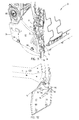
Referring now to FIGS. 14-18, the seat 201 of the seat assembly 200 includes a first seat side member 230 and a second seat side member 232, supported on first and second braces 252, 254, respectively. The seat 201 also includes a forward pan 240 that is supported on the first and second seat side members 230, 232. Spring members 242 extend from the forward pan 240 to a rear lateral member 244 and provide support to a cushion after assembly. The first brace 252 is operably connected with a first slide assembly 260 disposed on the rocker panel 26 of the vehicle 12. The second side brace 254 is operably connected with a second slide assembly 262 disposed on the transmission tunnel casing 80 of the vehicle 12. The first and second braces 252, 254 are suspended above the floor 60 of the vehicle 12 and do not touch the floor 60 of the vehicle 12, but instead are suspended from the rocker panel 26 and transmission tunnel casing 80, respectively. The first slide assembly 260 includes a rocker panel rail 264 and a first brace slide 266, which are slidably engaged. The second slide assembly 262 includes a transmission tunnel casing rail 268 and a second brace slide 270 that are slidably engaged. Together, the first slide assembly 260 and second slide assembly 262 allow linear translation of the entire seat assembly 200 between a forward position 272 (FIG. 19) and a rearward position 274 (FIG. 20). The planar extent of the first slide assembly 260 and the second slide assembly 262 is generally vertically aligned, as illustrated in FIG. 16.
Referring again to FIGS. 14-18, as well as FIGS. 24-26, the transmission tunnel casing rail 268 is fixedly connected with a forward support 280 and a rearward support 282 that are connected with the transmission tunnel casing 80. The second brace 254 of the seat assembly 200 is fixedly connected with the second brace slide 270, which is slidably connected with the transmission tunnel casing rail 268. Similarly, the rocker panel rail 264, which is fixedly connected with the rocker panel 26, is slidably connected with the first brace slide 266 of the first slide assembly 260. The first brace slide 266 is fixedly connected with the first brace 252. Therefore, the seat assembly 200 is allowed to move between the forward and rearward positions 272, 274 as the first brace slide 266 slides over the rocker panel rail 264 and the second base slide 270 slides over the transmission tunnel casing rail 268. It is generally contemplated that the first and second slide assemblies 260, 262 may include a plurality of ball bearings located between the first and second slides 266, 270 and the rails 264, 268, respectively, that allow for lateral translation of the seat 201 between the forward and rearward positions 272, 274, although other configurations, such as greased slides, etc., may also be used.
Referring now to FIGS. 21-23, the seat assembly 200 is also vertically movable between a lowered position 300 (FIG. 21) and a raised position 302 (FIG. 23). As shown in FIG. 21, the seat assembly 200 includes a toothed bracket 304 having a plurality of teeth 305 in communication with a gear 306. The toothed bracket 304 engages the first seat side member 230 of a pivot member 307. The gear 306 is operably connected with a motorized unit 310 (FIGS. 15 and 24) that is adapted to rotate the gear 306 in clockwise and counterclockwise directions. A rear portion of the seat 201 is connected to a rear support member 312. The rear support member 312 is rotatably coupled with the rear portion of the seat 201 at a top end thereof and the first brace 252 at a lower portion thereof. Rotation of the gear 306 by the motorized unit 310 in a counterclockwise direction results in the gear 306 rotating the toothed bracket 304 about a pivot point 313 in a clockwise direction. Consequently, the seat assembly 200 elevates from position A to position B (an intermediate position of the seat assembly 200, illustrated in FIG. 22). At the same time, the rear support member 312 rotates slightly clockwise, supporting a rear portion of the seat 201. Further rotation of the gear 306 in a counterclockwise direction causes further rotation of the toothed bracket 304 to a fully elevated position C (FIG. 23). At the same time, the rear support member 312 rotates in a clockwise direction, supporting the rear portion of the seat assembly 200 over the first brace 252. Forward and rearward seat supports 320, 322 (FIG. 26) connect the second brace 252 with the second seat side member 232. The forward and reward seat supports 320, 322 allow for raising and lowering of the seat 201. Thus, it will be understood that the rotation of the gear 306 moves the first seat side member 230 and the second seat side member 232 equally to allow for uniform raising and lowering of the seat assembly 200.
Notably, with respect to each embodiment discussed herein, the first and second braces are connected with the vehicle rocker panel and transmission tunnel, respectively, of the vehicle. Accordingly, the seat assembly of the present invention provides substantial leg and foot room beneath the seat assembly to provide additional comfort to a user sitting behind the seat assembly. Alternatively, the seat assembly can provide increased storage space for items that are to be transported in the vehicle. In addition, when a passenger is not present to sit on the seat assembly, the seat, when in the substantially vertical stowed position, provides additional cargo area for transporting various items in a foot well of a passenger seat.
It is to be understood that variations and modifications can be made on the aforementioned structure without departing from the concepts of the present invention, and further it is to be understood that such concepts are intended to be covered by the following claims unless these claims by their language expressly state otherwise.

Claims (12)

We claim:
1. A passenger seat assembly for a vehicle comprising:
a seat operably connected to a seat frame and rotatable between deployed and stowed positions, wherein the seat is rotatable relative to the frame about a first axis;
a forward seat pan pivotally coupled to first and second side seat members about a second axis;
a seatback rotatable relative to the frame about a third axis;
a first brace supporting the frame and movably connected to a vehicle rocker panel; and
a second brace supporting the frame and movably connected to a vehicle transmission tunnel.
2. The passenger seat assembly of claim 1, further comprising:
a first slide assembly connecting the first brace to the vehicle rocker panel and a second slide assembly connecting the second brace to the vehicle transmission tunnel.
3. The passenger seat assembly of claim 2, wherein a planar portion of the first and second slide assemblies is vertically aligned against the vehicle rocker panel and vehicle transmission tunnel, respectively.
4. The passenger seat assembly of claim 1, wherein the seat is rotatably and slidably connected to the frame.
5. The passenger seat assembly of claim 1, wherein the first and second braces each include a vertically-extending web with an upper support flange.
6. The passenger seat assembly of claim 1, wherein the seatback is disposed substantially directly above the first and second braces.
7. The passenger seat assembly of claim 1, wherein only the first and second braces support the seat inside the vehicle.
8. The passenger seat assembly of claim 1, wherein the seat is vertically adjustable between raised and lowered positions.
9. The passenger seat assembly of claim 5, wherein each vertically-extending web includes an inwardly-extending stop flange.
10. The passenger seat assembly of claim 9, wherein the first and second side seat members, each having an outwardly-extending engagement flange configured to abut the inwardly-extending stop flange on each vertically-extending web.
11. The passenger seat assembly of claim 1, wherein the first axis is positioned below and forward relative to the third axis.
12. A vehicle seat assembly comprising: a seat operably connected to a seat frame and rotatable relative thereto about a first axis between deployed and stowed positions; a seatback rotatable relative to the frame about a second axis; a first brace supporting the frame and disposed between the seat and a vehicle rocker panel; and a second brace positioned under the seat between sides of the frame and connecting the frame to a vehicle transmission tunnel.
US13/251,469 2011-10-03 2011-10-03 Adjustable floating seat Expired - Fee Related US8770646B2 (en)

Priority Applications (2)

Application Number Priority Date Filing Date Title
US13/251,469 US8770646B2 (en) 2011-10-03 2011-10-03 Adjustable floating seat
CN201220472156.6U CN202827207U (en) 2011-10-03 2012-09-14 Seat component and front passenger seat for vehicle

Applications Claiming Priority (1)

Application Number Priority Date Filing Date Title
US13/251,469 US8770646B2 (en) 2011-10-03 2011-10-03 Adjustable floating seat

Publications (2)

Publication Number Publication Date
US20130082478A1 US20130082478A1 (en) 2013-04-04
US8770646B2 true US8770646B2 (en) 2014-07-08

Family

ID=47938979

Family Applications (1)

Application Number Title Priority Date Filing Date
US13/251,469 Expired - Fee Related US8770646B2 (en) 2011-10-03 2011-10-03 Adjustable floating seat

Country Status (2)

Country Link
US (1) US8770646B2 (en)
CN (1) CN202827207U (en)

Cited By (7)

* Cited by examiner, † Cited by third party
Publication number Priority date Publication date Assignee Title
US9381962B2 (en) * 2014-09-12 2016-07-05 Dur-A-Bus Coach Builders Ltd. Passenger van
US9573490B1 (en) * 2015-09-24 2017-02-21 Fca Us Llc Reclining seat for a vehicle
USD780629S1 (en) 2014-09-12 2017-03-07 Dur-A-Bus Coach Builders Ltd. Bus
CN107738599A (en) * 2017-10-15 2018-02-27 佛山市神风航空科技有限公司 It is a kind of can be with the pony car of open passenger view
US9914371B2 (en) 2015-05-05 2018-03-13 Faurecia Automotive Seating, Llc Seat mover system
US9926027B2 (en) 2015-11-17 2018-03-27 Dur-A-Bus Coach Builders Ltd. Method for producing a bus
US10065536B2 (en) * 2015-09-24 2018-09-04 Fca Us Llc Reclining seat for a vehicle

Families Citing this family (2)

* Cited by examiner, † Cited by third party
Publication number Priority date Publication date Assignee Title
DE102012024429A1 (en) * 2012-12-14 2014-07-03 GM Global Technology Operations LLC (n. d. Gesetzen des Staates Delaware) vehicle seat
GB2541924B (en) * 2015-09-04 2018-04-18 Jaguar Land Rover Ltd Vehicle seat assembly

Citations (25)

* Cited by examiner, † Cited by third party
Publication number Priority date Publication date Assignee Title
US3258289A (en) * 1963-10-07 1966-06-28 Gen Motors Corp Vehicle seat
US3476435A (en) * 1966-05-20 1969-11-04 Daimler Benz Ag Motor vehicle seat
US4183493A (en) 1977-01-13 1980-01-15 Sears Manufacturing Company Roller fore-aft adjustment for a vehicle seat
US5320411A (en) 1991-11-25 1994-06-14 Kotobuki Seating Co., Ltd. Flip-up seat construction
US5711505A (en) * 1996-09-30 1998-01-27 Tachi-S Co., Ltd. Slide rail device for jump seat
US6012771A (en) * 1998-08-06 2000-01-11 Chrysler Corporation Seat fold mechanism
US20050057081A1 (en) * 2003-09-16 2005-03-17 Kahn Zaki A. Vehicle seat
US6883868B2 (en) * 2003-02-19 2005-04-26 Ts Tech Co., Ltd. Tip-up automotive seat provided with interlocking means
US20050146186A1 (en) * 2003-12-18 2005-07-07 Mazda Motor Corporation Seat device of vehicle
US6916057B2 (en) * 2003-02-20 2005-07-12 Deere & Company Folding vehicle seat
US6935691B1 (en) * 2004-04-13 2005-08-30 Tachi-S Co., Ltd. Vehicle seat with seat cushion tip-up structure
US20050218683A1 (en) * 2004-03-31 2005-10-06 Mazda Motor Corporation Seat device for vehicle
US20060113828A1 (en) * 2004-12-01 2006-06-01 Ryan Christopher J Flip and slide seat assembly
US7229117B2 (en) * 2005-05-20 2007-06-12 Toyota Boshoku Kabushiki Kaisha Vehicle seat moving devices
US7252318B2 (en) * 2004-03-30 2007-08-07 Mazda Motor Corporation Seat device for vehicle
US7374242B2 (en) * 2006-05-24 2008-05-20 Bae Industries, Inc. Seat latch assembly for a rear row standing seat including a slotted inertial lock plate with resistive support in both design and upright positions
US7434871B2 (en) * 2005-12-01 2008-10-14 Mazda Motor Corporation Lower vehicle body structure of vehicle
US7517008B2 (en) * 2006-02-07 2009-04-14 Toyota Motor Engineering & Manufacturing North America, Inc. Remote release seat cushion lock with one hand operation
US7611200B2 (en) * 2008-03-13 2009-11-03 Nissan Technical Center North America, Inc. Adjustable seat for use in a vehicle
US7780234B2 (en) * 2006-05-24 2010-08-24 Bae Industries, Inc. Inertial latch assembly such as incorporated into a rear row pivoting seat bottom including a slotted inertial lock plate with resistive support in both design and upright positions
US7854461B2 (en) 2006-05-19 2010-12-21 Ts Tech Co., Ltd. Slide/flip-up type seat for automobile
US20110209924A1 (en) * 2004-07-30 2011-09-01 Ts Tech Co., Ltd. Vehicle seat and passenger's weight measurement device for vehicle seat
US8104834B2 (en) * 2009-04-27 2012-01-31 Toyota Motor Engineering & Manufacturing North America, Inc. Automatic seat cushion locking mechanism with automatic tip-up
US8444223B2 (en) * 2009-04-27 2013-05-21 Toyota Motor Engineering & Manufacturing North America, Inc. Folding seat assembly having automatic seat cushion tip-up
US8459748B2 (en) * 2011-01-11 2013-06-11 Nissan North America, Inc. Vehicle seat assembly

Patent Citations (25)

* Cited by examiner, † Cited by third party
Publication number Priority date Publication date Assignee Title
US3258289A (en) * 1963-10-07 1966-06-28 Gen Motors Corp Vehicle seat
US3476435A (en) * 1966-05-20 1969-11-04 Daimler Benz Ag Motor vehicle seat
US4183493A (en) 1977-01-13 1980-01-15 Sears Manufacturing Company Roller fore-aft adjustment for a vehicle seat
US5320411A (en) 1991-11-25 1994-06-14 Kotobuki Seating Co., Ltd. Flip-up seat construction
US5711505A (en) * 1996-09-30 1998-01-27 Tachi-S Co., Ltd. Slide rail device for jump seat
US6012771A (en) * 1998-08-06 2000-01-11 Chrysler Corporation Seat fold mechanism
US6883868B2 (en) * 2003-02-19 2005-04-26 Ts Tech Co., Ltd. Tip-up automotive seat provided with interlocking means
US6916057B2 (en) * 2003-02-20 2005-07-12 Deere & Company Folding vehicle seat
US20050057081A1 (en) * 2003-09-16 2005-03-17 Kahn Zaki A. Vehicle seat
US20050146186A1 (en) * 2003-12-18 2005-07-07 Mazda Motor Corporation Seat device of vehicle
US7252318B2 (en) * 2004-03-30 2007-08-07 Mazda Motor Corporation Seat device for vehicle
US20050218683A1 (en) * 2004-03-31 2005-10-06 Mazda Motor Corporation Seat device for vehicle
US6935691B1 (en) * 2004-04-13 2005-08-30 Tachi-S Co., Ltd. Vehicle seat with seat cushion tip-up structure
US20110209924A1 (en) * 2004-07-30 2011-09-01 Ts Tech Co., Ltd. Vehicle seat and passenger's weight measurement device for vehicle seat
US20060113828A1 (en) * 2004-12-01 2006-06-01 Ryan Christopher J Flip and slide seat assembly
US7229117B2 (en) * 2005-05-20 2007-06-12 Toyota Boshoku Kabushiki Kaisha Vehicle seat moving devices
US7434871B2 (en) * 2005-12-01 2008-10-14 Mazda Motor Corporation Lower vehicle body structure of vehicle
US7517008B2 (en) * 2006-02-07 2009-04-14 Toyota Motor Engineering & Manufacturing North America, Inc. Remote release seat cushion lock with one hand operation
US7854461B2 (en) 2006-05-19 2010-12-21 Ts Tech Co., Ltd. Slide/flip-up type seat for automobile
US7374242B2 (en) * 2006-05-24 2008-05-20 Bae Industries, Inc. Seat latch assembly for a rear row standing seat including a slotted inertial lock plate with resistive support in both design and upright positions
US7780234B2 (en) * 2006-05-24 2010-08-24 Bae Industries, Inc. Inertial latch assembly such as incorporated into a rear row pivoting seat bottom including a slotted inertial lock plate with resistive support in both design and upright positions
US7611200B2 (en) * 2008-03-13 2009-11-03 Nissan Technical Center North America, Inc. Adjustable seat for use in a vehicle
US8104834B2 (en) * 2009-04-27 2012-01-31 Toyota Motor Engineering & Manufacturing North America, Inc. Automatic seat cushion locking mechanism with automatic tip-up
US8444223B2 (en) * 2009-04-27 2013-05-21 Toyota Motor Engineering & Manufacturing North America, Inc. Folding seat assembly having automatic seat cushion tip-up
US8459748B2 (en) * 2011-01-11 2013-06-11 Nissan North America, Inc. Vehicle seat assembly

Cited By (7)

* Cited by examiner, † Cited by third party
Publication number Priority date Publication date Assignee Title
US9381962B2 (en) * 2014-09-12 2016-07-05 Dur-A-Bus Coach Builders Ltd. Passenger van
USD780629S1 (en) 2014-09-12 2017-03-07 Dur-A-Bus Coach Builders Ltd. Bus
US9914371B2 (en) 2015-05-05 2018-03-13 Faurecia Automotive Seating, Llc Seat mover system
US9573490B1 (en) * 2015-09-24 2017-02-21 Fca Us Llc Reclining seat for a vehicle
US10065536B2 (en) * 2015-09-24 2018-09-04 Fca Us Llc Reclining seat for a vehicle
US9926027B2 (en) 2015-11-17 2018-03-27 Dur-A-Bus Coach Builders Ltd. Method for producing a bus
CN107738599A (en) * 2017-10-15 2018-02-27 佛山市神风航空科技有限公司 It is a kind of can be with the pony car of open passenger view

Also Published As

Publication number Publication date
CN202827207U (en) 2013-03-27
US20130082478A1 (en) 2013-04-04

Similar Documents

Publication Publication Date Title
US8770646B2 (en) Adjustable floating seat
US7677656B2 (en) Modular seat/console for a vehicle
US7255384B2 (en) Vehicle seat that tips and kneels and folds into a stowage well
US9187012B2 (en) Pivoting and reclining vehicle seating assembly
US6827394B2 (en) Vehicle seat system
JP6230590B2 (en) Vehicle seat
US20130082500A1 (en) Flip-up floating seat
JP5746424B2 (en) Stadium and retractable seats
US9649957B2 (en) Second row vehicle seat
US8287048B2 (en) Pinch guard for a vehicle seat
GB2386550A (en) Adjustable seat
CN112140955A (en) Adjustable seat assembly
CA2874041C (en) Fold and kneel seat with rearward folding motion
US9333885B2 (en) Folding vehicle seat
US9604553B2 (en) Virtual H-point seat back system
US9840176B1 (en) Seat with integrated foldable table
JP6470035B2 (en) Table device for seat
JP7449756B2 (en) seat equipment
US20230191960A1 (en) Vehicle seat
JPWO2014125631A1 (en) Vehicle seat
JP7216272B2 (en) Seat storage structure
JP2018095062A (en) seat
JP2019011001A (en) Seat device for vehicle
JP2002120607A (en) Seat device for vehicle

Legal Events

Date Code Title Description
AS Assignment

Owner name: FORD GLOBAL TECHNOLOGIES, LLC, MICHIGAN

Free format text: ASSIGNMENT OF ASSIGNORS INTEREST;ASSIGNORS:LINE, JOHNATHAN ANDREW, MR.;HARPER, KENDRICK ALDEN, MR.;JARANSON, JOHN W., MR.;AND OTHERS;SIGNING DATES FROM 20110923 TO 20111003;REEL/FRAME:027093/0609

STCF Information on status: patent grant

Free format text: PATENTED CASE

MAFP Maintenance fee payment

Free format text: PAYMENT OF MAINTENANCE FEE, 4TH YEAR, LARGE ENTITY (ORIGINAL EVENT CODE: M1551)

Year of fee payment: 4

FEPP Fee payment procedure

Free format text: MAINTENANCE FEE REMINDER MAILED (ORIGINAL EVENT CODE: REM.); ENTITY STATUS OF PATENT OWNER: LARGE ENTITY

LAPS Lapse for failure to pay maintenance fees

Free format text: PATENT EXPIRED FOR FAILURE TO PAY MAINTENANCE FEES (ORIGINAL EVENT CODE: EXP.); ENTITY STATUS OF PATENT OWNER: LARGE ENTITY

STCH Information on status: patent discontinuation

Free format text: PATENT EXPIRED DUE TO NONPAYMENT OF MAINTENANCE FEES UNDER 37 CFR 1.362

FP Lapsed due to failure to pay maintenance fee

Effective date: 20220708