US8752742B2 - Holster assembly and method using same - Google Patents
Holster assembly and method using same Download PDFInfo
- Publication number
- US8752742B2 US8752742B2 US11/455,412 US45541206A US8752742B2 US 8752742 B2 US8752742 B2 US 8752742B2 US 45541206 A US45541206 A US 45541206A US 8752742 B2 US8752742 B2 US 8752742B2
- Authority
- US
- United States
- Prior art keywords
- holster
- assembly
- trigger guard
- moveable
- inches
- Prior art date
- Legal status (The legal status is an assumption and is not a legal conclusion. Google has not performed a legal analysis and makes no representation as to the accuracy of the status listed.)
- Expired - Fee Related, expires
Links
Images


Classifications
-
- F—MECHANICAL ENGINEERING; LIGHTING; HEATING; WEAPONS; BLASTING
- F41—WEAPONS
- F41C—SMALLARMS, e.g. PISTOLS, RIFLES; ACCESSORIES THEREFOR
- F41C33/00—Means for wearing or carrying smallarms
- F41C33/02—Holsters, i.e. cases for pistols having means for being carried or worn, e.g. at the belt or under the arm
- F41C33/0281—Holsters, i.e. cases for pistols having means for being carried or worn, e.g. at the belt or under the arm with means for assisting in cocking or loading the small arm
Definitions
- the invention relates to a holster for a handgun, and a method using same.
- holster assembly that facilitates loading a round into the firing chamber, and assists the removal of the loaded pistol from the holster. Applicant's holster assembly, and method using same, achieves these objectives.
- Applicant's invention includes a holster, comprising a base; a barrel housing assembly fixedly attached to said base; and a moveable trigger guard assembly slidably attached to the barrel housing assembly, and one or more springs disposed between the barrel housing assembly and the moveable trigger guard assembly, wherein the moveable trigger guard assembly can be slidingly moved bidirectionally between a first position and a second position.
- FIG. 1A is a perspective view of the base portion of Applicant's holster assembly
- FIG. 1B is a top view of the base portion of FIG. 1A ;
- FIG. 1C is a bottom view of the base portion of FIG. 1A ;
- FIG. 1D is a side view of the base portion of FIG. 1A ;
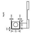
- FIG. 2A is a perspective view showing the base of FIG. 1A in combination with a riser
- FIG. 2B is a side view showing the elements of FIG. 2A ;
- FIG. 2C is a top view showing the elements of FIG. 2A ;
- FIG. 3A is a perspective view showing the elements of FIG. 2A in combination with Applicants' barrel housing;
- FIG. 3B is a top view showing the elements of FIG. 3A ;
- FIG. 3C is a side view showing one of the elements of FIG. 3A ;
- FIG. 4A is a perspective view showing the elements of FIG. 3A in combination with two slide rail elements
- FIG. 4B is a side view a first slide rail
- FIG. 4C is a side view of a second slide rail
- FIG. 4D shows a subassembly comprising Applicants' slide rails attached to Applicants' barrel housing
- FIG. 5A is a perspective view showing the elements of FIG. 4A in combination with a slide block moveably disposed within each of Applicants' slide rails, wherein those slide blocks are disposed in a first position;
- FIG. 5B is a side view of a first slide rail formed to include a first aperture, wherein a first spring and a first slide block are disposed within that first aperture, wherein the first slide block is in a first position and wherein the first spring comprises an elongated configuration;
- FIG. 5C is a side view of a second slide rail formed to include a second aperture, wherein a second spring and a second slide block are disposed within that second aperture, wherein the second slide block is in a first position and wherein the second spring comprises an elongated configuration;
- FIG. 5D is a perspective view showing Applicants' slide blocks moved to a second position
- FIG. 5E is a side view of the first slide rail of FIG. 5B , wherein the first slide block is in the second position of FIG. 5D , and wherein the first spring comprises a compressed configuration;
- FIG. 5F is a side view of the second slide rail of FIG. 5C , wherein the second slide block is in the second position of FIG. 5D , and wherein the second spring comprises a compressed configuration;
- FIG. 5G is a side view showing the elements of FIG. 5A ;
- FIG. 6A is a perspective view showing the elements of FIG. 5A in combination with Applicants' trigger guard
- FIG. 6B is a perspective view showing an element of Applicants' trigger guard
- FIG. 6C is a perspective view showing an additional element of Applicants' trigger guard
- FIG. 7A is a perspective view of Applicant's holster showing the moveable trigger guard in a first position
- FIG. 7B is a perspective view of Applicant's holster showing the moveable trigger guard in a second position
- FIG. 8A is a perspective view showing a pistol removeably disposed within Applicants' holster assembly, wherein Applicants' moveable trigger guard is shown in the first position of FIG. 7A ;
- FIG. 8B is a perspective view showing a pistol removeably disposed within Applicants' holster assembly, wherein Applicants' moveable trigger guard is shown in the second position of FIG. 7B ;
- FIG. 8C is a side view of a self-loading pistol in an operational configuration
- FIG. 8D is a side view of the pistol of FIG. 8C in a loading configuration
- FIG. 9 is a flow chart summarizing the steps of Applicant's method.
- FIG. 7A shows a perspective view of Applicant's holster assembly 700 .
- FIG. 8A shows a perspective view of Applicant's holster assembly 700 with pistol 810 removeably disposed therein.
- Applicant's holster assembly 700 facilitates loading a round into the firing chamber of pistol 810 , and assists the removal of the loaded pistol from the holster.
- Applicant's holster assembly and method allow the user to load pistol 810 using only one hand. Using prior art holsters, two hands are needed to withdraw and load a pistol from a holster.
- Such one-handed operation allows disabled persons, or persons having limited use of one arm, to operate an automatic pistol for self protection, hunting, competition, or target shooting in general.
- one-handed operation is a significant benefit for police, military, and/or security personnel. For example, if a police officer is detaining a suspect with one hand and another person charges towards that officer, using a prior art holster the officer would have to release the suspect in order to use both hands to draw and cycle the pistol. Using Applicant's holster assembly and method, however, the officer can continue to detain the suspect with one hand, dispose a round into the firing chamber of the pistol in the holster with the other hand, and draw the pistol on the charging person without releasing the suspect.
- Applicant's holster assembly 700 comprises base 110 .
- Base 110 comprises a planar member having a first end 111 , a second end 113 , a first width 116 A at end 111 , and a second width 116 B at end 113 .
- Ends 111 and 113 are interconnected by a first side 115 having length 114 , and a second side 117 , wherein side 117 is parallel to side 115 for a distance 118 measured from first end 111 , and wherein side 117 then tapers inwardly toward side 115 thereafter.
- Base 110 further comprises a thickness 119 , optional first clip 121 , and optional second clip 123 .
- base 110 is formed from a rigid material, such as without limitation wood, metal, molded plastic, leather, combinations thereof, and the like.
- length 114 is between about 4 inches and about 12 inches. In certain embodiments, length 114 is about 9 inches. In certain embodiments, width 116 A is between about 2 inches and about 6 inches. In certain embodiments, width 116 A is about 4 inches. In certain embodiments, width 116 B is between about 0.50 inches and about 3 inches. In certain embodiments, width 116 B is about 1 inch.
- thickness 119 is between about 0.20 inches and about 0.50 inches. In certain embodiments, thickness 119 is about 0.30 inches. In certain embodiments, width 116 A tapers after length 118 to width 116 B at end 113 .
- first clip 121 and second clip 123 can be used to attach Applicants' holster assembly 700 to a belt, pant, or other clothing portion.
- clips 121 and 123 are integrally molded with base 110 .
- clip 121 and/or clip 123 are separately formed, and subsequently attached to base 110 using conventional attachment means, such as and without limitation, adhesive bonding, welding, and the like.
- First clip 121 and second clip 123 comprise a length 120 . In certain embodiments, length 120 is between about 2 inches and 3 inches.
- riser 210 comprises a first side 211 attached to base 110 and an opposing second side 213 .
- Riser 210 further comprises length 212 , height 214 , and width 216 .
- length 212 is between about 4 inches and about 12 inches. In certain embodiments, length 212 is about 7 inches.
- height 214 is between about 0.75 inches and about 1.50 inches. In certain embodiments, height 214 is about 1 inch.
- width 216 is between about 0.50 inches and about 1 inch. In certain embodiments, width 216 is about 0.75 inches.
- barrel housing 310 comprises base planar member 320 , side planar member 330 , and top planar member 340 .
- Housing 310 is mounted on side 213 of riser 210 such that member 330 is flush with side 215 of riser 210 .
- top planar member 340 is formed to include aperture 350 .
- housing 310 comprises an integrally molded assembly.
- base planar member 320 , side planar member 330 , and top planar member 340 comprise separate elements which are attached to one another using conventional attachment means.
- base 110 , riser 210 , and housing 310 comprise an integrally molded assembly.
- Base planar member 320 has a length 358 , width 323 , and thickness 325 .
- length 358 is between about 4 inches and about 12 inches. In certain embodiments, length 358 is about 9 inches.
- width 323 is between about 0.5 inches and about 2 inches. In certain embodiments, width 323 is about 1.30 inches.
- thickness 325 is between about 0.05 inches and about 0.15 inches. In certain embodiments, thickness 325 is about 0.09 inches
- Side planar member 330 is attached to base member 320 , and extends upwardly therefrom.
- Side planar member 330 has a length 358 , a height 327 , and a thickness 329 .
- height 327 is between about 0.50 inches and about 2 inches. In certain embodiments, height 327 is about 1.30 inches. In certain embodiments, height 327 is between about 0.5 inches and about 2 inches. In certain embodiments, height 327 is about 1.33 inches.
- thickness 329 is between about 0.05 inches and about 0.15 inches. In certain embodiments, thickness 329 is about 0.09 inches.
- Aperture 350 has a length 352 and width 354 .
- length 352 is between about 0.50 inch and about 2 inches. In certain embodiments, length 352 is about 1.33 inches. In certain embodiments, width 354 is between about 0.50 inches and about 2 inches. In certain embodiments, width 354 is about 1 inch.
- Top planar member 340 is attached to side planar member 330 and extends inwardly therefrom.
- Top planar member 340 has a length 358 , a width 356 , and a thickness 335 .
- width 356 is between about 0.5 inches and about 2 inches. In certain embodiments, width 356 is about 1.30 inches. In certain embodiments, thickness 335 is between about 0.05 inches and about 0.15 inches. In certain embodiments, thickness 335 is about 0.09 inches.
- barrel port block 360 comprises a rectangular parallelepiped formed to include aperture 362 extending therethrough, wherein aperture 362 comprises a cylindrical shape.
- aperture 362 comprises a shape selected from the group consisting of an inverted “U” shape, an “H” shape, and the like.
- Barrel port block 360 is disposed in distal end 312 of housing 310 .
- aperture 362 has a diameter between about 0.5 inches and about 1 inches. In certain embodiments, aperture 362 has a diameter of about 0.7 inches.
- first slide rail 410 and second slide rail 420 are attached to housing 310 such that side 416 and side 426 are flush with edge 342 and edge 322 , respectively, of housing 310 .
- slide rail 420 is attached to the side of riser 210 such that side 426 is flush with edge 322 .
- slide rail 410 and slide rail 420 are formed from a rigid material, such as without limitation wood, metal, molded plastic, leather, combinations thereof, and the like.
- Slide rail 410 and slide rail 420 comprise length 430 , width 413 , and thickness 415 .
- length 430 is between about 2 inches and about 10 inches. In certain embodiments, length 430 is about 6 inches.
- width 413 is between about 0.25 inches and about 1 inch. In certain embodiments, width 413 is about 0.375 inches.
- thickness 415 is between about 0.25 inches and about 1 inch. In certain embodiments, thickness 415 is about 0.375 inches.
- slide rail 410 and slide rail 420 are attached to housing 310 using conventional attachment means, such as and without limitation adhesive bonding, welding, plastic welding, mechanical fasteners, i.e. nuts, bolts, and the like.
- slide rail 410 , slide rail 420 , and housing 310 comprise an integrally molded assembly.
- Slide rail 410 comprises a tubular member formed to include aperture 440 .
- aperture 440 is about 4 inches long and about 0.25 inches wide.
- Slide rail 420 comprises a tubular member formed to include aperture 450 .
- aperture 450 is about 4 inches long and about 0.25 inches wide.
- slide block 510 is slidingly disposed in aperture 440 .
- Slide block 510 comprises first end 512 and opposing second end 514 .
- Slide block 520 is slidingly disposed in aperture 450 .
- Slide block 520 comprises first end 522 and opposing second end 524 .
- slide block 510 comprises length 513 and width 516 .
- Slide block 510 extends outwardly from slide rail 410 a distance 518 .
- slide block 520 comprises length 523 , and width 526 . Slide block 520 extends outwardly from slide rail 420 a distance 528 .
- lengths 513 and 523 are between about 0.50 inches and about 3 inches. In certain embodiments, lengths 513 and 523 are about 2 inches. In certain embodiments, distance 518 is between about 0.25 inches and about 1.50 inches. In certain embodiments, distance 518 is about 0.75 inches. In certain embodiments, distance 528 is between about 0.25 inches and about 1.50 inches. In certain embodiments, distance 528 is about 0.75 inches.
- width 516 is between about 0.12 inches and about 0.50 inch. In certain embodiments, width 516 is about 0.25 inches. In certain embodiments, width 526 is between about 0.12 inches and about 0.50 inch. In certain embodiments, width 526 is about 0.25 inches.
- spring 530 is disposed within aperture 440 with one end of that springe in contact with end 514 of slide block 510 .
- spring 530 exerts a first force against slide block 510 thereby disposing slide block in 510 the first configuration shown in FIGS. 5A and 5B .
- spring 540 is disposed within aperture 450 with one end of that spring in contact with end 524 of slide block 520 .
- spring 540 exerts a second force against slide block 520 thereby disposing slide block 520 in the first configuration shown in FIGS. 5A and 5C .
- FIG. 5D shows slide block 510 and slide block 520 in a second configuration.
- spring 530 is placed in the compressed configuration shown in FIG. 5E .
- spring 530 exerts a third force on slide block 510 , wherein that third force is greater than the first force described hereinabove.
- spring 540 when slide block 520 is moved fowardly within aperture 450 into the second configuration of FIG. 5D , spring 540 is placed in the compressed configuration shown in FIG. 5F .
- spring 540 exerts a fourth force on slide block 520 , wherein that fourth force is greater than the second force described hereinabove.
- trigger guard 610 comprises side member 612 , side member 614 , and interconnecting member 616 .
- side member 612 , side member 614 , and interconnecting member 616 comprise irregular-shaped members.
- trigger guard 610 comprises an integrally molded assembly.
- side member 612 , side member 614 , and interconnecting member 616 are separately formed and then attached as shown using conventional attachment means.
- Side members 612 and 614 are attached to slide block 510 and slide block 520 , respectively, and extend outwardly therefrom.
- FIGS. 7A and 8A show holser assembly 700 wherein moveable trigger guard 610 is disposed in a first position.
- FIG. 7B shows and 8 B show holster assembly 700 wherein moveable trigger guard 610 has been slidably moved to a second position to load pistol 810 .
- Applicant's invention comprises a method to holster and load a self-loading pistol, wherein that pistol as initially holstered using Applicant's holster assembly and method does not have a round in the firing chamber.
- FIG. 9 summarizes the steps of Applicant's method.
- Applicant's method provides a holster, such as Applicant's holster assembly 700 as described herein, comprising a base; a barrel housing assembly fixedly attached to the base, and a moveable trigger guard assembly slidably disposed on the barrel housing assembly.
- Applicant's barrel housing assembly comprises housing 310 in combination with slide rail 410 , and slide rail 420 .
- Applicants' moveable trigger guard assembly comprises trigger guard 610 in combination with slide block 510 and slide block 520 .
- Applicants' trigger guard assembly can be slidingly moved bidirectionally between a first position shown in FIG. 7A and a second position shown in FIG. 7B , wherein the moveable trigger guard assembly is initially disposed in the first position shown in FIG. 7A .
- step 905 further comprises steps 910 and 920 .
- Applicant's method provides a holster comprising one or more springs, such as spring 530 and/or spring 540 , wherein each of those one or more springs is disposed between a portion of Applicants' barrel housing assembly and a portion of Applicant's moveable trigger guard assembly.
- the one or more springs of step 910 exert an aggregate upward force, holding Applicants' moveable trigger guard assembly in a first position shown in FIG. 7A .
- Applicant's method provides a self-loading pistol comprising a trigger, a barrel, a firing chamber, a moveable slide mechanism, a grip, and one or more rounds disposed in the grip, wherein the moveable slide mechanism can be slidingly moved between a first position and a second position, wherein the slide mechanism is disposed in the first position.
- One of the one or more rounds is loaded into the firing chamber when the moveable slide mechanism is moved to the second position
- a self-loading pistol reloads the firing chamber with a new round automatically each time the weapon is fired, without additional action by the user. This is accomplished by recoil.
- a semi-automatic pistol will fire only one shot per trigger pull, in contrast to a “fully automatic” pistol which continues to fire as long as the trigger is held back or until all rounds have been fired.
- self-loading pistol 810 comprises grip 812 , slide mechanism 814 , trigger 816 , and barrel 818 .
- pistol 810 further comprises a clip mechanism disposed within grip 812 , wherein that clip mechanism is designed to hold a plurality of rounds, i.e. bullets, and to feed a round into the firing chamber each time a round is fired.
- slide mechanism 814 in order to load a round into the firing chamber slide mechanism 814 is moved backwardly manually to configuration 811 , thereby causing the clip mechanism to load a round into the firing chamber.
- moving slide mechanism 814 backwardly also cocks a trigger.
- an internal spring mechanism pulls slide mechanism forward to the configuration shown in FIG. 8C with a round loaded in the firing chamber.
- pistol 810 automatically reloads until the supply of rounds disposed in the clip assembly is depleted.
- step 940 Applicant's method removeably disposes the self-loading pistol of step 930 in the holster of step 905 such that the trigger is removeably inserted into the moveable trigger guard assembly, and such that the barrel is removeably inserted into the barrel housing assembly, wherein the self-loading pistol does not have a round in the firing chamber.
- FIGS. 8A and 8C FIG. 8A shows pistol 810 removeably disposed in Applicant's holster assembly 700 such that barrel portion 818 is removeably disposed in the barrel housing assembly of Applicant's holster, and such that trigger 816 is removeably disposed in Applicant's trigger guard assembly, as that assembly is described and defined herein.
- step 950 Applicant's method slides the moveable trigger guard assembly from the first position of FIG. 8A to the second position of FIG. 8B , thereby sliding the moveable slide mechanism 814 from the first position of FIG. 8C to the second position of FIG. 8D .
- Step 950 comprises exerting a downward force on grip 812 , thereby sliding moveable trigger guard assembly from the first position shown in FIG. 8A to the second position shown in FIG. 8B , thereby placing pistol 810 in the loading configuration shown in FIG. 8D .
- FIGS. 5E , 5 F, and 8 B sliding Applicant's trigger guard assembly to the second position shown in FIG. 8B , compresses spring 530 and/or spring 540 as shown in FIGS. 5E and 5F , respectively.
- step 970 After pistol 810 is placed in the loading configuration of FIG. 8D , in step 970 , a round is disposed in the firing chamber thereby “loading” the pistol.
- step 995 Applicant's method removes the loaded pistol from Applicant's holster assembly.
- step 995 comprises steps 980 and 990 .
- step 980 Applicant's method releases the downward force exerted in step 960 .
- step 990 the one or more compressed springs 530 and/or 540 push the trigger guard assembly back to the first position thereby assisting the removal of pistol 810 from holster assembly 700 .
- Applicant's holster assembly 700 also allows the user to unload pistol 810 using one hand.
- the user After the user has cycled, drawn, and fired pistol 810 , there may be a live round in the firing chamber.
- the user then, using the hand carrying pistol 810 causes pistol 810 to eject the clip, and any live rounds disposed therein, from grip portion 812 , and then using that same hand inserts pistol 810 into holster assembly 700 , and using that same hand pushes pistol 810 downwardly such that pistol 810 is disposed in the configuration of FIG. 8D .
- Disposing pistol 810 in the configuration of FIG. 8D causes the live round in the firing chamber to be ejected through aperture 350 in barrel housing 310 , thereby unloading pistol 810 .
- Another live round cannot be placed in the firing chamber because the clip has been removed.
- the user may forget that pistol 810 has a round in the firing chamber when the user cycles the pistol using Applicant's holster assembly 700 .
- the round already disposed in the firing chamber is ejected, and a different live round is placed into the chamber from the loaded magazine or clip.
- holster assembly 700 can also be used to carry pistol 810 without using Applicant's method.
- pistol 810 is withdrawn from holster assembly 700 without pushing that pistol downwardly to load a round in the firing chamber, and without engaging the upward pull of compressed springs 530 and/or 540 to assist removal of the pistol from the holster assembly.
- Applicant's holster assembly 700 can be fashioned to work with either a right-handed carry, or a left-handed carry.
- right-handed carry Applicant's mean that pistol 810 is grasped using the right hand, pushed downwardly using the right hand, and removed from holster assembly 700 using the right hand.
Landscapes
- Engineering & Computer Science (AREA)
- General Engineering & Computer Science (AREA)
- Knives (AREA)
- User Interface Of Digital Computer (AREA)
- Toys (AREA)
- Packaging Of Annular Or Rod-Shaped Articles, Wearing Apparel, Cassettes, Or The Like (AREA)
Abstract
Description
Claims (6)
Priority Applications (2)
| Application Number | Priority Date | Filing Date | Title |
|---|---|---|---|
| US11/455,412 US8752742B2 (en) | 2005-11-30 | 2006-06-19 | Holster assembly and method using same |
| PCT/US2007/014356 WO2008097251A2 (en) | 2006-06-19 | 2007-06-19 | Holster assembly and method using same |
Applications Claiming Priority (2)
| Application Number | Priority Date | Filing Date | Title |
|---|---|---|---|
| US11/291,631 US8752741B2 (en) | 2005-11-30 | 2005-11-30 | Holster assembly and method using same |
| US11/455,412 US8752742B2 (en) | 2005-11-30 | 2006-06-19 | Holster assembly and method using same |
Related Parent Applications (1)
| Application Number | Title | Priority Date | Filing Date |
|---|---|---|---|
| US11/291,631 Continuation-In-Part US8752741B2 (en) | 2005-11-30 | 2005-11-30 | Holster assembly and method using same |
Publications (2)
| Publication Number | Publication Date |
|---|---|
| US20100219216A1 US20100219216A1 (en) | 2010-09-02 |
| US8752742B2 true US8752742B2 (en) | 2014-06-17 |
Family
ID=39682232
Family Applications (1)
| Application Number | Title | Priority Date | Filing Date |
|---|---|---|---|
| US11/455,412 Expired - Fee Related US8752742B2 (en) | 2005-11-30 | 2006-06-19 | Holster assembly and method using same |
Country Status (2)
| Country | Link |
|---|---|
| US (1) | US8752742B2 (en) |
| WO (1) | WO2008097251A2 (en) |
Cited By (4)
| Publication number | Priority date | Publication date | Assignee | Title |
|---|---|---|---|---|
| US9879944B1 (en) | 2014-04-08 | 2018-01-30 | Taser International, Inc. | Systems and methods for cooperation among weapons, holsters, and recorders |
| US10040401B1 (en) * | 2016-08-08 | 2018-08-07 | Echo Zulu, LLC | Locking firearm holder |
| US20210372728A1 (en) * | 2018-07-23 | 2021-12-02 | Charlie R. Cerda | Firearm mounting device |
| US11933581B1 (en) * | 2022-09-13 | 2024-03-19 | Richard Levette | Rifle stock with magnetic pistol holder |
Families Citing this family (10)
| Publication number | Priority date | Publication date | Assignee | Title |
|---|---|---|---|---|
| US8684242B2 (en) * | 2006-01-23 | 2014-04-01 | Eagle Industries Unlimited, Inc. | Holster with interchangeable cowlings |
| EP2204630A3 (en) | 2009-01-06 | 2013-06-12 | Evgeny Abushaev | Self-loading holster for semi-automatic or automatic pistols |
| CN102313490B (en) * | 2010-07-06 | 2015-12-09 | 也夫根尼·阿布沙耶夫 | Self-loading holster for semi-automatic or automatic pistol |
| TR201006950A2 (en) * | 2010-08-20 | 2011-07-21 | Erteki̇n Seydi̇ | Side slide sleeve mechanism with fast one-handed gun. |
| TR201006952A2 (en) * | 2010-08-20 | 2011-06-21 | Erteki̇n Seydi̇ | U-shaped spring and slide sleeve mechanism, which can be quickly loaded with one hand. |
| TR201006949A2 (en) * | 2010-10-08 | 2011-08-22 | Erteki̇n Seydi̇ | One-hand quick gun refill holster mechanism. |
| ITMI20112176A1 (en) * | 2011-11-29 | 2013-05-30 | Fulvio Buonavoglia | SEMI-AUTOMATIC PISTOL HOLSTER WITH AUXILIARY ARMORING MECHANISM |
| WO2016123078A1 (en) * | 2015-01-26 | 2016-08-04 | Jon Rossi | Self-disguising holster |
| US9791226B1 (en) * | 2016-04-20 | 2017-10-17 | Nathan David Bozzo | Bolt action slide conversion device |
| IL256692B (en) * | 2018-01-01 | 2018-10-31 | Ages Daniel | Pistol-loading holster apparatus |
Citations (9)
| Publication number | Priority date | Publication date | Assignee | Title |
|---|---|---|---|---|
| US1046912A (en) | 1912-04-27 | 1912-12-10 | George M Wanee | Gun-holder. |
| US1557339A (en) * | 1924-01-31 | 1925-10-13 | John R Sander | Pistol-holding device |
| US2132323A (en) * | 1937-04-28 | 1938-10-04 | John R Sander | Pistol holding device |
| US3105611A (en) * | 1962-06-19 | 1963-10-01 | Conti Vincent | Cartridge carrier and dispenser |
| US3763587A (en) | 1969-08-18 | 1973-10-09 | I Firmalino | In-cranked automatic pistol |
| US3804306A (en) | 1972-06-08 | 1974-04-16 | S Azurin | Automatic pistol holster |
| US4138044A (en) | 1977-10-18 | 1979-02-06 | Musgrave Daniel D | Pistol charging holster |
| US4298150A (en) | 1980-08-21 | 1981-11-03 | Richard Seldeen | Pistol charging holster |
| US6948644B1 (en) * | 2001-08-13 | 2005-09-27 | Bianchi International | Movable welt holster |
-
2006
- 2006-06-19 US US11/455,412 patent/US8752742B2/en not_active Expired - Fee Related
-
2007
- 2007-06-19 WO PCT/US2007/014356 patent/WO2008097251A2/en not_active Ceased
Patent Citations (9)
| Publication number | Priority date | Publication date | Assignee | Title |
|---|---|---|---|---|
| US1046912A (en) | 1912-04-27 | 1912-12-10 | George M Wanee | Gun-holder. |
| US1557339A (en) * | 1924-01-31 | 1925-10-13 | John R Sander | Pistol-holding device |
| US2132323A (en) * | 1937-04-28 | 1938-10-04 | John R Sander | Pistol holding device |
| US3105611A (en) * | 1962-06-19 | 1963-10-01 | Conti Vincent | Cartridge carrier and dispenser |
| US3763587A (en) | 1969-08-18 | 1973-10-09 | I Firmalino | In-cranked automatic pistol |
| US3804306A (en) | 1972-06-08 | 1974-04-16 | S Azurin | Automatic pistol holster |
| US4138044A (en) | 1977-10-18 | 1979-02-06 | Musgrave Daniel D | Pistol charging holster |
| US4298150A (en) | 1980-08-21 | 1981-11-03 | Richard Seldeen | Pistol charging holster |
| US6948644B1 (en) * | 2001-08-13 | 2005-09-27 | Bianchi International | Movable welt holster |
Cited By (7)
| Publication number | Priority date | Publication date | Assignee | Title |
|---|---|---|---|---|
| US9879944B1 (en) | 2014-04-08 | 2018-01-30 | Taser International, Inc. | Systems and methods for cooperation among weapons, holsters, and recorders |
| US10040401B1 (en) * | 2016-08-08 | 2018-08-07 | Echo Zulu, LLC | Locking firearm holder |
| US20210372728A1 (en) * | 2018-07-23 | 2021-12-02 | Charlie R. Cerda | Firearm mounting device |
| US11619464B2 (en) * | 2018-07-23 | 2023-04-04 | Vulcan Arms LLC | Firearm mounting device |
| US20230272993A1 (en) * | 2018-07-23 | 2023-08-31 | Vulcan Arms, Llc | Firearm mounting device |
| US12313363B2 (en) | 2018-07-23 | 2025-05-27 | Vulcan Arms, Llc | Firearm mounting device |
| US11933581B1 (en) * | 2022-09-13 | 2024-03-19 | Richard Levette | Rifle stock with magnetic pistol holder |
Also Published As
| Publication number | Publication date |
|---|---|
| WO2008097251A2 (en) | 2008-08-14 |
| US20100219216A1 (en) | 2010-09-02 |
| WO2008097251A3 (en) | 2008-11-27 |
Similar Documents
| Publication | Publication Date | Title |
|---|---|---|
| WO2008097251A2 (en) | Holster assembly and method using same | |
| US10955208B2 (en) | Automatic spent magazine ejection and control group | |
| CN1069399C (en) | insurance and development agency | |
| US7257919B1 (en) | Magazine loader | |
| US7497043B2 (en) | Magazine doubler | |
| US10760874B2 (en) | Concealable firearm | |
| CN100458356C (en) | Lockable holster for handheld firearm | |
| US8438774B2 (en) | Pistol cocking assistive device | |
| US20130232843A1 (en) | Magazine Loading Device for Loading Bullets or Cartridges into a Magazine | |
| US12215951B2 (en) | Firearm with spare magazine storage facility | |
| US8826577B1 (en) | Shotgun shoulder stock shell carrier | |
| US20120036757A1 (en) | Gun-stock riser for AR15 type tactical firearm | |
| US20160370138A1 (en) | Spring-adjustment assembly of firearm magazine | |
| US8122635B2 (en) | Shotgun forearm-stock shot shell carrier | |
| US8752741B2 (en) | Holster assembly and method using same | |
| US4914845A (en) | Breech load pistol and conversion | |
| US4936035A (en) | Breech load pistol and conversion | |
| US10077958B2 (en) | Recoil spring for a firearm | |
| US10365056B2 (en) | Magazine follower for enhancing reliability of firearms and firearm magazines | |
| US10012463B2 (en) | Firearm magazine release assist device | |
| US12305952B2 (en) | Systems and methods related to selective capture of spent shell casings | |
| MXPA97009779A (en) | Assembly of security and desplie |
Legal Events
| Date | Code | Title | Description |
|---|---|---|---|
| AS | Assignment |
Owner name: STEVENS AND CLARK, L.L.C., ARIZONA Free format text: ASSIGNMENT OF ASSIGNORS INTEREST;ASSIGNOR:CLARK, WILLIAM E.;REEL/FRAME:018484/0320 Effective date: 20060614 |
|
| AS | Assignment |
Owner name: STEVENS & CLARK, L.L.C., ARIZONA Free format text: ASSIGNMENT OF ASSIGNORS INTEREST;ASSIGNOR:STEVENS, VICTOR;REEL/FRAME:021447/0588 Effective date: 20060614 |
|
| AS | Assignment |
Owner name: SLIDETEK LLC, WASHINGTON Free format text: CHANGE OF NAME;ASSIGNOR:STEVENS & CLARK, L.L.C.;REEL/FRAME:032845/0627 Effective date: 20100916 |
|
| STCF | Information on status: patent grant |
Free format text: PATENTED CASE |
|
| MAFP | Maintenance fee payment |
Free format text: PAYMENT OF MAINTENANCE FEE, 4TH YR, SMALL ENTITY (ORIGINAL EVENT CODE: M2551) Year of fee payment: 4 |
|
| FEPP | Fee payment procedure |
Free format text: MAINTENANCE FEE REMINDER MAILED (ORIGINAL EVENT CODE: REM.); ENTITY STATUS OF PATENT OWNER: SMALL ENTITY |
|
| LAPS | Lapse for failure to pay maintenance fees |
Free format text: PATENT EXPIRED FOR FAILURE TO PAY MAINTENANCE FEES (ORIGINAL EVENT CODE: EXP.); ENTITY STATUS OF PATENT OWNER: SMALL ENTITY |
|
| STCH | Information on status: patent discontinuation |
Free format text: PATENT EXPIRED DUE TO NONPAYMENT OF MAINTENANCE FEES UNDER 37 CFR 1.362 |
|
| FP | Lapsed due to failure to pay maintenance fee |
Effective date: 20220617 |