US8745606B2 - Critical section ordering for multiple trace applications - Google Patents
Critical section ordering for multiple trace applications Download PDFInfo
- Publication number
- US8745606B2 US8745606B2 US11/863,703 US86370307A US8745606B2 US 8745606 B2 US8745606 B2 US 8745606B2 US 86370307 A US86370307 A US 86370307A US 8745606 B2 US8745606 B2 US 8745606B2
- Authority
- US
- United States
- Prior art keywords
- critical
- code
- dependence
- critical sections
- graph
- Prior art date
- Legal status (The legal status is an assumption and is not a legal conclusion. Google has not performed a legal analysis and makes no representation as to the accuracy of the status listed.)
- Expired - Fee Related, expires
Links
Images


Classifications
-
- G—PHYSICS
- G06—COMPUTING OR CALCULATING; COUNTING
- G06F—ELECTRIC DIGITAL DATA PROCESSING
- G06F8/00—Arrangements for software engineering
- G06F8/40—Transformation of program code
- G06F8/41—Compilation
- G06F8/44—Encoding
- G06F8/443—Optimisation
-
- G—PHYSICS
- G06—COMPUTING OR CALCULATING; COUNTING
- G06F—ELECTRIC DIGITAL DATA PROCESSING
- G06F8/00—Arrangements for software engineering
- G06F8/40—Transformation of program code
- G06F8/41—Compilation
- G06F8/43—Checking; Contextual analysis
- G06F8/433—Dependency analysis; Data or control flow analysis
Definitions
- This disclosure relates generally to compiling technologies in a computing system, and more specifically but not exclusively, to code optimization techniques.
- Multithreading and multiprocessing are common programming techniques often used to maximize the efficiency of computer programs by providing a tool to permit concurrency or multitasking. Threads are ways for a computer program to be divided into multiple and distinct sequences of programming instructions where each sequence is treated as a single task and to be processed simultaneously.
- One example application that may use the multithreaded programming technique is a packet-switched network application that processes network packets in a high speed packet-switched system concurrently.
- a new thread may be created for each incoming packet.
- the processor may divide its time between different threads.
- different threads may be processed on different processors.
- the Intel® IXATM network processors (IXPs) have multiple microengines (MEs) processing network packets in parallel where each ME supports multiple threads.
- critical sections are created by using a signal mechanism in a multiprocessor system.
- a signal may be used to permit entering or to indicate exiting of a critical section.
- packets are distributed to a chain of threads in order (i.e., an earlier thread in the chain processes an earlier packet).
- Each thread waits for a signal from the previous thread before entering the critical section. After the signal is received, the thread executes the critical section code exclusively. Once this thread is done, it sends the signal to the next thread after leaving the critical section.
- critical section merge is typically performed by a compiler when optimizing a code.
- the size of a critical section also affects the performance of a programming code. Typically the larger a critical section is, the longer the shared resource access latency is. Additionally, a small sized critical section is normally easier to be hidden by technologies such as multithreading than a large-sized critical section. Hence, a compiler also performs critical section minimization in addition to critical section merge when optimizing a code. Code motion techniques may be used to at least partly merge critical sections and reduce sizes of critical sections. To merge critical sections, it is desirable to first determine the order of critical sections since the order of critical sections may be different across different traces.
- FIG. 1 is a block diagram of an exemplary computing system in which an example embodiment of the subject matter disclosed in the present application may be implemented;
- FIG. 2 is a block diagram that illustrates a compiler according to an example embodiment of the subject matter disclosed in the present application
- FIG. 3 is a block diagram of an exemplary critical section ordering apparatus according to an example embodiment of the subject matter disclosed in the present application;
- FIGS. 4A , 4 B and 4 C illustrate an example of performing initiative motions to identify positions of critical sections according to an example embodiment of the subject matter disclosed in the present application
- FIGS. 5A and 5B illustrate an example of determining the order of critical sections, according to an example embodiment of the subject matter disclosed in the present application.
- FIG. 6 is a flowchart of one example process for critical section ordering for a multiple trace application, according to an example embodiment of the subject matter disclosed in the present application.
- critical sections may be ordered based at least in part on code motions when optimizing a code.
- a flow graph of a program including the critical section may be generated.
- Two initiative motions may be performed based on the flow graph to identify positions of critical codes in the flow graph.
- Dependence relationship of critical sections may be determined based on the positions of critical sections. Using the dependence relationship information, the order of critical sections may be determined. The determined order of critical sections may be further used by a compiler to perform optimizations for the code.
- FIG. 1 is a block diagram of an exemplary computing system 100 in which an example embodiment of the subject matter disclosed in the present application may be implemented.
- the computing system 100 includes a processor 101 that processes data and a memory 113 .
- the processor 101 may have multiple or many processing cores (for brevity of description, term “multiple cores” will be used hereinafter to include both multiple processing cores and many processing cores).
- the processor 101 may be a complex instruction set microprocessor, a reduced instruction set computing microprocessor, a very long instruction word computer microprocessor, a processor implementing a combination of instruction sets, or other processor device.
- FIG. 1 shows the computing system 100 with a single processor. However, it is understood that the computing system 100 may operate with multiple processors. Additionally, each of the one or more processors may support one or more hardware threads.
- the processor 101 is coupled to a CPU (Central Processing Unit) bus 110 that transmits data signals between processor 101 and other components in the computing system 100 .
- CPU Central Processing Unit
- the memory 113 may be a dynamic random access memory (“DRAM”) device, a static random access memory (“SRAM”) device, read-only memory (“ROM”), a synchronous DRAM (“SDRAM”) device, a Double Data Rate (“DDR”) SDRAM device, and/or other memory device.
- the memory 113 may store instructions and code represented by data signals that may be executed by the processor 101 .
- a compiler may be stored in the memory 113 and implemented by the processor 101 in the computing system 100 .
- the compiler may derive the flow graph of a program including multiple critical sections with multiple traces. Two initiative motions may be performed based on the flow graph to identify positions of critical codes in the flow graph.
- Dependence relationship of critical sections may be determined based on the positions of critical sections. Using the dependence relationship information, the order of critical sections may be determined. The determined order of critical sections may be further used by a compiler to perform optimizations for the code.
- a cache 102 may reside inside processor 101 to store data stored in memory 113 .
- the cache 102 speeds access to memory by the processor 101 by taking advantage of its locality of access.
- the cache 102 may reside external to the processor 101 .
- the cache 102 may include multiple levels, such as level 1 cache (L1 cache), level 2 cache (L2 cache), level 3 cache, and so on, with one or more levels (e.g., L1 cache) residing inside the processor 101 and others residing outside the processor 101 .
- a bridge memory controller 111 directs data signals between the processor 101 , the memory 113 , and other components in the computing system 100 and bridges the data signals between the CPU bus 110 , the memory 113 , and a first IO (Input/Output) bus 120 .
- the first IO bus 120 may be a single bus or a combination of multiple buses.
- the first IO bus 120 provides communication links between components in the computer system 100 .
- a network controller 121 may be coupled to the first IO bus 120 .
- the network controller 121 may link the computing system 100 to a network of computers (not shown) and support communication among the computers.
- a display device controller 122 may be coupled to the first IO bus 120 .
- the display device controller 122 allows coupling of a display device (not shown) to the computing system 100 and acts as an interface between the display device and the computing system 100 .
- a second IO bus 130 may be a single bus or a combination of multiple buses.
- the second IO bus 130 may provide communication links between components in the computing system 100 .
- a data storage device 131 is coupled to the second IO bus 130 .
- the data storage device 131 may be hard disk drive, a floppy disk drive, a compact disc (“CD”) ROM device, a flash memory device or other mass storage device.
- An input interface 132 may be coupled to the second IO bus 130 .
- the input interface 132 may be, for example, a keyboard and/or mouse controller to other input interface.
- the input interface 132 may be a dedicated device or can reside in another device such as a bus controller or other controller.
- the input interface 132 allows coupling of an input device to the computing system 100 and transmits data signals from an input device to the computing system 100 .
- An audio controller 133 may be coupled to the second IO bus 130 .
- the audio controller 133 operates to coordinate the recording and playing of sounds by a device such as an audio codec which is also coupled to the IO bus 130 .
- a bus bridge 123 couples the first IO bus 120 and the second IO bus 130 .
- the bus bridge 123 operates to buffer and bridge data signals between the first IO bus 120 and the second IO bus 130 .
- a program When a program is executed in the computing system 100 , it may be executed in multiple threads. In one embodiment, all of the threads may be running on processor 101 . In another embodiment, threads may be distributed and run on multiple processor or processing cores. Threads communicate to other threads through shared resources such as global memory, registers, or signals. In many instances, the shared resource may only be accessed by one thread. Such an exclusive access of the shared resource by one thread at a time may be implemented by using a critical section.
- a conventional method to implement a critical section is to use a signal mechanism. A thread may enter a critical section after receiving a signal and exiting the critical section by notifying the next thread that it is done and by passing a signal to the next thread. Typically, it is desirable to merge critical sections to reduce the number of signals being used and to minimize sizes of critical sections to reduce the latency of shared resource access. In a multiple trace application the order of critical sections needs to be determined so that critical section merger and minimization can be efficiently performed.
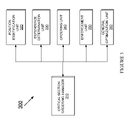
- FIG. 2 is a block diagram that illustrates a compiler 200 according to an example embodiment of the subject matter disclosed in the present application.
- the compiler 200 may include a compiler manager 210 .
- the compiler manager 210 receives source code to compile.
- the compiler manager 210 interfaces with and transmits information between other components in the compiler 200 .
- the compiler 200 may include a front end unit 220 . According to an embodiment of the compiler 200 , the front end unit 220 operates to parse source code and convert it to an abstract syntax tree.
- the compiler 200 may also include an intermediate language (“IL”) unit 230 .
- the IL unit 230 transforms the abstract syntax tree into a common intermediate form such as an intermediate representation. It should be appreciated that the IL unit 230 may transform the abstract syntax tree into one or more common intermediate forms.
- the complier may include an optimizer unit 240 .
- the optimizer unit 240 may utilize one or more optimization procedures to optimize the intermediate representation of the code.
- the optimizer unit 240 may perform peephole, local, loop, global, interprocedural and/or other optimizations.
- the optimizer unit 240 includes a critical section ordering apparatus 241 .
- the critical section ordering apparatus may perform two initiative motions based on the flow graph of a program to identify positions of critical codes in the program that include multiple critical sections with multiple traces.
- the critical section ordering apparatus may determine the dependence relationship of critical sections based on the positions of critical sections. Using the dependence relationship information, the critical section ordering apparatus may determine the order of critical sections.
- the determined order of critical sections may be further used by a compiler to perform optimizations for the code.
- the compiler 200 may include a register allocator unit 250 .
- the register allocator unit 250 identifies data in the intermediate representation that may be stored in registers in the processor rather than in memory.
- the compiler 200 may include a code generator 260 .
- the code generator 260 converts the intermediate representation into machine or assembly code.
- FIG. 3 is a block diagram of an exemplary critical section ordering apparatus 300 according to an example embodiment of the subject matter disclosed in the present application.
- the critical section ordering apparatus 300 may be used to implement the critical section ordering apparatus 241 shown in FIG. 2 .
- the critical section ordering apparatus 300 includes a critical section ordering manager 310 .
- the critical section ordering manager 310 interfaces with and transmits information between other components in the critical section ordering apparatus 300 .
- Critical section ordering apparatus 300 may include a position identification unit 320 .
- the position identification unit 320 may receive a flow graph of a program having multiple critical sections with multiple traces.
- the position identification unit 320 may perform two initiative motions for instructions in the program—“code sink” and “code hoist.”
- FIGS. 4A , 4 B, and 4 C illustrate an example of two initiative motions according to an example embodiment of the subject matter disclosed in the present application.
- FIG. 4A shows the original flow graph 400 of an example code.
- the original flow graph 400 shows that there are two critical sections: CS # 1 and CS # 2 .
- CS # 1 starts with CSBegin 1 in block 1 and ends with CSEnd 1 in block 4 .
- FIG. 4B shows a flow graph 430 after an initiative motion—code sink of the example code.
- the code sink motion keeps all of the CSEnd's at the last block of the flow graph and sinks all of the CSBegin's as low as possible in the flow graph.
- CSBegin 1 is moved from block 1 and block 2 ; while CSBegin 2 is moved to block 4 after CSEnd 1 but before CSEnd 2 . From flow graph 430 , the lowest possible positions of CSBegin's across different traces may be obtained.
- FIG. 4C shows a flow graph 470 of the example code after another initiative motion—code hoist.
- the code hoist motion keeps all CSBegin's at the top of the flow graph and hoist all of the CSEnd's as high as possible.
- CSBegin 1 and CSBegin 2 remain in block 1 ;
- CSEnd 2 is moved from block 4 to block 1 and is placed after CSBegin 2 ;
- CSEnd 1 remains in block 4 . From flow graph 470 , the highest possible positions of CSEnd's across different traces may be obtained.
- flow graphs 400 , 430 , and 470 remains the same, i.e., relationship between code blocks are the same for flow graphs 400 , 430 , and 470 .
- What is different among flow graph 400 , 430 , and 470 is what is inside each code block.
- what block 1 includes in flow graph 400 is different from what is included in block 1 in flow graph 430 , which is also different from what is included in block 1 in flow graph 470 .
- Such unchanged block-level flow graph may be referred to as control flow graph.
- the lowest possible position for CSBegin 1 is block 2 and the highest possible position for CSEnd 1 is block 4 . It can also be found that the lowest possible position for CSBegin 2 is block 4 and the highest possible position for CSEnd 2 is block 1 .
- critical section ordering apparatus 300 also includes a dependence determination unit 330 to determine the dependence relationship among critical sections based on the position results obtained from position determination unit 320 . Two reasonable decisions for ordering critical sections may be made after obtaining the position information of critical sections. First, for the i th critical section, if the lowest possible position of CSBegin i (CBLow i ) is higher than the highest possible position of CSEnd i (CEHigh i ) on a single trace, the minimal critical section on this trace must be from CBLow i to CEHigh i assuming the control flow graph remains the same.
- dependence relationships may be added into critical section a dependence graph using a formula such as: If ( CB Low1 ⁇ CE High2), add dependence CS 1 ⁇ CS 2; If ( CB Low2 ⁇ CE High1), add dependence CS 2 ⁇ CS 1. In other words, if the condition “CBLow1 ⁇ CEHigh2” is met, it means that it is impossible to sink CS 1 after CS 2 , and the best order for these two critical sections should be (CS 1 , CS 2 ). To enforce this order, a dependence CS 1 ⁇ CS 2 may be added.
- the dependence relationships among different critical sections may be inserted into the dependence graph on a single trace.
- critical section dependence relationships on multiple traces may be inserted into the dependence graph trace by trace. If two critical section relationship on a trace is affected by another trace, these two dependence relationships of the two critical sections on the two trances should be consistent because they are both obtained based on the same initiative motions. Thus, it is possible to add two consistent dependence relationships of two critical sections on two traces on the same dependence graph. On the other hand, if two critical sections relationships on different traces are irrelative to each other, both dependence relationships may be added to the dependence graph. Hence, dependence relationships obtained using the method disclosed above may be applied to multiple trace situations.
- Critical section ordering apparatus 300 may also include an ordering unit 340 to determine the order of critical sections across different traces.
- the ordering unit summarizes the dependence graph obtained from dependence determination unit 330 ; partitions critical sections into different groups; and decides the order of these groups. This is an order summary of all these critical sections.
- FIGS. 5A and 5B illustrate an example of determining the order of critical sections based on a dependence graph obtained from dependence determination unit 330 , according to an example embodiment of the subject matter disclosed in the present application.
- FIG. 5A shows a dependence graph 500 obtained from dependence determination unit 330 . Each node in graph 500 represents a critical section.
- Ordering unit 34 summarizes all the nodes in graph 500 to derive a summarized dependence graph 550 as shown in FIG. 5B .
- Graph 550 includes two summarized nodes. From the summarized graph 550 , the order of the four critical sections as shown in FIGS. 5A and 5B may be decided, i.e., (1, 2, 3) ⁇ (4).
- critical section ordering apparatus 300 may also include a enforcement unit 350 to provide the compiler with the order of critical sections obtained from ordering unit 340 ; and inform the compiler to enforce the order when perform optimizations for the program code (e.g., critical section merger, critical section minimization, etc.).
- a enforcement unit 350 to provide the compiler with the order of critical sections obtained from ordering unit 340 ; and inform the compiler to enforce the order when perform optimizations for the program code (e.g., critical section merger, critical section minimization, etc.).
- Critical section ordering apparatus 300 may also include a general optimization unit 360 .
- the general optimization unit 360 applies general optimization methods such as code scheduling and copy optimizations to hide resource access latency.
- FIG. 6 is a flowchart of one example process 600 for critical section ordering for a multiple trace application, according to an example embodiment of the subject matter disclosed in the present application.
- a flow graph of a program code may be received.
- initiative motions such as code sink and code hoist may be performed to identify possible positions of critical sections on different traces.
- dependence relationships among critical sections on different traces may be obtained based on the possible positions of the critical sections obtained in block 620 .
- the order of critical sections may be determined using the dependence information obtained in block 630 .
- the determined order of critical sections may be provided to the compiler which then enforces this order when performing optimizations to the program code.
- code optimizations including critical section merger and critical section minimization may be performed.
- Various embodiments of the disclosed subject matter may be implemented in hardware, firmware, software, or combination thereof, and may be described by reference to or in conjunction with program code, such as instructions, functions, procedures, data structures, logic, application programs, design representations or formats for simulation, emulation, and fabrication of a design, which when accessed by a machine results in the machine performing tasks, defining abstract data types or low-level hardware contexts, or producing a result.
- program code such as instructions, functions, procedures, data structures, logic, application programs, design representations or formats for simulation, emulation, and fabrication of a design, which when accessed by a machine results in the machine performing tasks, defining abstract data types or low-level hardware contexts, or producing a result.
- program code may represent hardware using a hardware description language or another functional description language which essentially provides a model of how designed hardware is expected to perform.
- Program code may be assembly or machine language, or data that may be compiled and/or interpreted.
- Program code may be stored in, for example, volatile and/or non-volatile memory, such as storage devices and/or an associated machine readable or machine accessible medium including solid-state memory, hard-drives, floppy-disks, optical storage, tapes, flash memory, memory sticks, digital video disks, digital versatile discs (DVDs), etc., as well as more exotic mediums such as machine-accessible biological state preserving storage.
- a machine readable medium may include any mechanism for storing, transmitting, or receiving information in a form readable by a machine, and the medium may include a tangible medium such as antennas, optical fibers, communications interfaces, etc.
- Program code may be transmitted in the form of packets, serial data, parallel data, propagated signals, etc., and may be used in a compressed or encrypted format.
- Program code may be implemented in programs executing on programmable machines such as mobile or stationary computers, personal digital assistants, set top boxes, cellular telephones and pagers, and other electronic devices, each including a processor, volatile and/or non-volatile memory readable by the processor, at least one input device and/or one or more output devices.
- Program code may be applied to the data entered using the input device to perform the described embodiments and to generate output information.
- the output information may be applied to one or more output devices.
- programmable machines such as mobile or stationary computers, personal digital assistants, set top boxes, cellular telephones and pagers, and other electronic devices, each including a processor, volatile and/or non-volatile memory readable by the processor, at least one input device and/or one or more output devices.
- Program code may be applied to the data entered using the input device to perform the described embodiments and to generate output information.
- the output information may be applied to one or more output devices.
- One of ordinary skill in the art may appreciate that embodiments of the disclosed subject
Landscapes
- Engineering & Computer Science (AREA)
- General Engineering & Computer Science (AREA)
- Theoretical Computer Science (AREA)
- Software Systems (AREA)
- Physics & Mathematics (AREA)
- General Physics & Mathematics (AREA)
- Devices For Executing Special Programs (AREA)
Abstract
Description
If (CBLow1<CEHigh2), add dependence CS1→CS2;
If (CBLow2<CEHigh1), add dependence CS2→CS1.
In other words, if the condition “CBLow1<CEHigh2” is met, it means that it is impossible to sink CS1 after CS2, and the best order for these two critical sections should be (CS1, CS2). To enforce this order, a dependence CS1→CS2 may be added. Similarly, when the condition “CBLow2<CEHigh1” is met, it means that it is impossible to hoist CS1 before CS2, and the best order for these two critical sections should be (CS2, CS1). To enforce this order, a dependence CS2→CS1 may be added to the dependence graph of critical sections.
Claims (19)
Priority Applications (1)
| Application Number | Priority Date | Filing Date | Title |
|---|---|---|---|
| US11/863,703 US8745606B2 (en) | 2007-09-28 | 2007-09-28 | Critical section ordering for multiple trace applications |
Applications Claiming Priority (1)
| Application Number | Priority Date | Filing Date | Title |
|---|---|---|---|
| US11/863,703 US8745606B2 (en) | 2007-09-28 | 2007-09-28 | Critical section ordering for multiple trace applications |
Publications (2)
| Publication Number | Publication Date |
|---|---|
| US20090089765A1 US20090089765A1 (en) | 2009-04-02 |
| US8745606B2 true US8745606B2 (en) | 2014-06-03 |
Family
ID=40509877
Family Applications (1)
| Application Number | Title | Priority Date | Filing Date |
|---|---|---|---|
| US11/863,703 Expired - Fee Related US8745606B2 (en) | 2007-09-28 | 2007-09-28 | Critical section ordering for multiple trace applications |
Country Status (1)
| Country | Link |
|---|---|
| US (1) | US8745606B2 (en) |
Cited By (5)
| Publication number | Priority date | Publication date | Assignee | Title |
|---|---|---|---|---|
| US9792443B1 (en) * | 2015-03-12 | 2017-10-17 | Whitehat Security, Inc. | Position analysis of source code vulnerabilities |
| US9851957B2 (en) * | 2015-12-03 | 2017-12-26 | International Business Machines Corporation | Improving application code execution performance by consolidating accesses to shared resources |
| US10210077B2 (en) | 2016-05-18 | 2019-02-19 | International Business Machines Corporation | Using multiple sequence alignment to identify security vulnerability code paths |
| US11526429B1 (en) * | 2021-09-01 | 2022-12-13 | Sap Se | Identifying critical methods and critical paths in software code |
| US11640504B2 (en) | 2019-05-17 | 2023-05-02 | Samsung Electronics Co., Ltd. | Electronic apparatus and controlling method thereof |
Families Citing this family (22)
| Publication number | Priority date | Publication date | Assignee | Title |
|---|---|---|---|---|
| US8543992B2 (en) * | 2005-12-17 | 2013-09-24 | Intel Corporation | Method and apparatus for partitioning programs to balance memory latency |
| US8037466B2 (en) * | 2006-12-29 | 2011-10-11 | Intel Corporation | Method and apparatus for merging critical sections |
| JP2014075046A (en) * | 2012-10-04 | 2014-04-24 | International Business Maschines Corporation | Trace generation method, device, and program, and multilevel compilation using the method |
| US8954546B2 (en) | 2013-01-25 | 2015-02-10 | Concurix Corporation | Tracing with a workload distributor |
| US8997063B2 (en) | 2013-02-12 | 2015-03-31 | Concurix Corporation | Periodicity optimization in an automated tracing system |
| US8924941B2 (en) | 2013-02-12 | 2014-12-30 | Concurix Corporation | Optimization analysis using similar frequencies |
| US20130283281A1 (en) | 2013-02-12 | 2013-10-24 | Concurix Corporation | Deploying Trace Objectives using Cost Analyses |
| US20130219372A1 (en) | 2013-03-15 | 2013-08-22 | Concurix Corporation | Runtime Settings Derived from Relationships Identified in Tracer Data |
| US20140317604A1 (en) * | 2013-04-20 | 2014-10-23 | Concurix Corporation | Real Time Analysis of Tracer Summaries to Change Tracer Behavior |
| US20140317603A1 (en) * | 2013-04-20 | 2014-10-23 | Concurix Corporation | Multiple Tracer Configurations Applied on a Function-by-Function Level |
| US9575874B2 (en) | 2013-04-20 | 2017-02-21 | Microsoft Technology Licensing, Llc | Error list and bug report analysis for configuring an application tracer |
| WO2014171982A1 (en) * | 2013-04-20 | 2014-10-23 | Concurix Corporation | Tracer list for automatically controlling tracer behavior |
| US8978016B2 (en) | 2013-04-20 | 2015-03-10 | Concurix Corporation | Error list and bug report analysis for configuring an application tracer |
| US8966452B2 (en) | 2013-04-20 | 2015-02-24 | Concurix Corporation | User interaction analysis of tracer data for configuring an application tracer |
| US9021445B2 (en) | 2013-04-20 | 2015-04-28 | Concurix Corporation | Tracer list for automatically controlling tracer behavior |
| US9734040B2 (en) | 2013-05-21 | 2017-08-15 | Microsoft Technology Licensing, Llc | Animated highlights in a graph representing an application |
| US8990777B2 (en) | 2013-05-21 | 2015-03-24 | Concurix Corporation | Interactive graph for navigating and monitoring execution of application code |
| US9280841B2 (en) | 2013-07-24 | 2016-03-08 | Microsoft Technology Licensing, Llc | Event chain visualization of performance data |
| US9292415B2 (en) | 2013-09-04 | 2016-03-22 | Microsoft Technology Licensing, Llc | Module specific tracing in a shared module environment |
| US9772927B2 (en) | 2013-11-13 | 2017-09-26 | Microsoft Technology Licensing, Llc | User interface for selecting tracing origins for aggregating classes of trace data |
| WO2015071777A1 (en) | 2013-11-13 | 2015-05-21 | Concurix Corporation | Software component recommendation based on multiple trace runs |
| CN107203401B (en) * | 2016-03-17 | 2020-11-06 | 创新先进技术有限公司 | A front-end project construction method, device and system |
Citations (2)
| Publication number | Priority date | Publication date | Assignee | Title |
|---|---|---|---|---|
| US20050108695A1 (en) * | 2003-11-14 | 2005-05-19 | Long Li | Apparatus and method for an automatic thread-partition compiler |
| US20060136878A1 (en) * | 2004-12-17 | 2006-06-22 | Arun Raghunath | Method and apparatus for enabling compiler and run-time optimizations for data flow applications in multi-core architectures |
-
2007
- 2007-09-28 US US11/863,703 patent/US8745606B2/en not_active Expired - Fee Related
Patent Citations (2)
| Publication number | Priority date | Publication date | Assignee | Title |
|---|---|---|---|---|
| US20050108695A1 (en) * | 2003-11-14 | 2005-05-19 | Long Li | Apparatus and method for an automatic thread-partition compiler |
| US20060136878A1 (en) * | 2004-12-17 | 2006-06-22 | Arun Raghunath | Method and apparatus for enabling compiler and run-time optimizations for data flow applications in multi-core architectures |
Non-Patent Citations (1)
| Title |
|---|
| U.S. Appl. No. 11/662,217, filed Mar. 8, 2007, entitled "Method and Apparatus for Ordering Code Based on Critical Sections," by Long Li, et al. |
Cited By (5)
| Publication number | Priority date | Publication date | Assignee | Title |
|---|---|---|---|---|
| US9792443B1 (en) * | 2015-03-12 | 2017-10-17 | Whitehat Security, Inc. | Position analysis of source code vulnerabilities |
| US9851957B2 (en) * | 2015-12-03 | 2017-12-26 | International Business Machines Corporation | Improving application code execution performance by consolidating accesses to shared resources |
| US10210077B2 (en) | 2016-05-18 | 2019-02-19 | International Business Machines Corporation | Using multiple sequence alignment to identify security vulnerability code paths |
| US11640504B2 (en) | 2019-05-17 | 2023-05-02 | Samsung Electronics Co., Ltd. | Electronic apparatus and controlling method thereof |
| US11526429B1 (en) * | 2021-09-01 | 2022-12-13 | Sap Se | Identifying critical methods and critical paths in software code |
Also Published As
| Publication number | Publication date |
|---|---|
| US20090089765A1 (en) | 2009-04-02 |
Similar Documents
| Publication | Publication Date | Title |
|---|---|---|
| US8745606B2 (en) | Critical section ordering for multiple trace applications | |
| US8037465B2 (en) | Thread-data affinity optimization using compiler | |
| US9652286B2 (en) | Runtime handling of task dependencies using dependence graphs | |
| US8984498B2 (en) | Variance analysis for translating CUDA code for execution by a general purpose processor | |
| US7882498B2 (en) | Method, system, and program of a compiler to parallelize source code | |
| US10133827B2 (en) | Automatic generation of multi-source breadth-first search from high-level graph language | |
| US8453134B2 (en) | Improving data locality and parallelism by code replication | |
| US7890943B2 (en) | Code optimization based on loop structures | |
| JP7708369B2 (en) | System and method for automatic parallelization of processing code for multiprocessor systems with optimized latency - Patents.com | |
| US9361118B2 (en) | Method for memory consistency among heterogeneous computer components | |
| JP2010529559A (en) | Parallelizing sequential frameworks using transactions | |
| US8966461B2 (en) | Vector width-aware synchronization-elision for vector processors | |
| US10318261B2 (en) | Execution of complex recursive algorithms | |
| Augonnet et al. | A unified runtime system for heterogeneous multi-core architectures | |
| Fukuhara et al. | Automated kernel fusion for GPU based on code motion | |
| Wittig et al. | Access interval prediction for tightly coupled memory systems | |
| US8037466B2 (en) | Method and apparatus for merging critical sections | |
| WO2007128168A1 (en) | Thread scheduling on multiprocessor systems | |
| US10564948B2 (en) | Method and device for processing an irregular application | |
| US20070079079A1 (en) | Apparatus, systems and methods to reduce access to shared data storage | |
| US8453131B2 (en) | Method and apparatus for ordering code based on critical sections | |
| US8543992B2 (en) | Method and apparatus for partitioning programs to balance memory latency | |
| Neelima et al. | Communication and computation optimization of concurrent kernels using kernel coalesce on a GPU | |
| US20080282237A1 (en) | Method and Apparatus For Generating Execution Equivalence Information | |
| US20050251795A1 (en) | Method, system, and program for optimizing code |
Legal Events
| Date | Code | Title | Description |
|---|---|---|---|
| AS | Assignment |
Owner name: INTEL CORPORATION, CALIFORNIA Free format text: ASSIGNMENT OF ASSIGNORS INTEREST;ASSIGNORS:GUO, XIAOFENG;DAI, JINQUAN;LI, LONG;REEL/FRAME:020782/0646;SIGNING DATES FROM 20071015 TO 20071229 Owner name: INTEL CORPORATION, CALIFORNIA Free format text: ASSIGNMENT OF ASSIGNORS INTEREST;ASSIGNORS:GUO, XIAOFENG;DAI, JINQUAN;LI, LONG;SIGNING DATES FROM 20071015 TO 20071229;REEL/FRAME:020782/0646 |
|
| FEPP | Fee payment procedure |
Free format text: PAYOR NUMBER ASSIGNED (ORIGINAL EVENT CODE: ASPN); ENTITY STATUS OF PATENT OWNER: LARGE ENTITY |
|
| STCF | Information on status: patent grant |
Free format text: PATENTED CASE |
|
| MAFP | Maintenance fee payment |
Free format text: PAYMENT OF MAINTENANCE FEE, 4TH YEAR, LARGE ENTITY (ORIGINAL EVENT CODE: M1551) Year of fee payment: 4 |
|
| FEPP | Fee payment procedure |
Free format text: MAINTENANCE FEE REMINDER MAILED (ORIGINAL EVENT CODE: REM.); ENTITY STATUS OF PATENT OWNER: LARGE ENTITY |
|
| LAPS | Lapse for failure to pay maintenance fees |
Free format text: PATENT EXPIRED FOR FAILURE TO PAY MAINTENANCE FEES (ORIGINAL EVENT CODE: EXP.); ENTITY STATUS OF PATENT OWNER: LARGE ENTITY |
|
| STCH | Information on status: patent discontinuation |
Free format text: PATENT EXPIRED DUE TO NONPAYMENT OF MAINTENANCE FEES UNDER 37 CFR 1.362 |
|
| FP | Lapsed due to failure to pay maintenance fee |
Effective date: 20220603 |