US8738293B2 - Apparatus and method for multi-sensor estimation of a property of an earth formation - Google Patents
Apparatus and method for multi-sensor estimation of a property of an earth formation Download PDFInfo
- Publication number
- US8738293B2 US8738293B2 US12/777,511 US77751110A US8738293B2 US 8738293 B2 US8738293 B2 US 8738293B2 US 77751110 A US77751110 A US 77751110A US 8738293 B2 US8738293 B2 US 8738293B2
- Authority
- US
- United States
- Prior art keywords
- sensors
- property
- sensor array
- model
- carrier
- Prior art date
- Legal status (The legal status is an assumption and is not a legal conclusion. Google has not performed a legal analysis and makes no representation as to the accuracy of the status listed.)
- Expired - Fee Related, expires
Links
Images


Classifications
-
- G—PHYSICS
- G01—MEASURING; TESTING
- G01V—GEOPHYSICS; GRAVITATIONAL MEASUREMENTS; DETECTING MASSES OR OBJECTS; TAGS
- G01V7/00—Measuring gravitational fields or waves; Gravimetric prospecting or detecting
-
- G—PHYSICS
- G01—MEASURING; TESTING
- G01V—GEOPHYSICS; GRAVITATIONAL MEASUREMENTS; DETECTING MASSES OR OBJECTS; TAGS
- G01V11/00—Prospecting or detecting by methods combining techniques covered by two or more of main groups G01V1/00 - G01V9/00
Definitions
- various properties of earth formations are measured by lowering measurement tools into a drilled borehole. For example, field of gravity measurements are taken in boreholes to monitor deep water fluids within underground reservoirs. From a geophysical point of view, a high level of precision and repeatability of borehole measurements determine the success of monitoring earth formations. Data of a high quality obtained through a high quality measurement tool may be contaminated by errors due to a poor level of repeatability.
- Depth error of the tool position i.e., movement of the tool producing variations in depth over repeated measurements, leads to errors in the measured signal.
- downhole gravity measurements include an additional error term (“ ⁇ g”) due to an input from the normal gradient (“ ⁇ g 0 ”) of the gravity field, and also due to variations in the medium in which the measurements are performed (“ ⁇ g s ”).
- ⁇ g is a unit of gravitational acceleration (“g”) equal to 1 cm/sec 2 .
- this additional term is approximated by a double Bouguer correction.
- the error ⁇ g in tool positioning can be interpreted as a random measurement error depending on rock density and relative displacement.
- An apparatus for estimating a property of an earth formation includes: a plurality of sensors configured to estimate at least one property, each of the plurality of sensors located at a known position relative to one another; and a processor in operable communication with the plurality of sensors and configured to estimate uncertainties of the location of the plurality of sensors over a period of time.
- a method of estimating a property of an earth formation includes: disposing a plurality of sensors at a selected location, the plurality of sensors located at a known position relative to one another; estimating at least one property via the plurality of sensors by taking at least two measurements with the plurality of sensors, each of the at least two measurements being temporally separated within a selected time period; and estimating uncertainties of the location of the plurality of sensors within the selected time period.
- a computer program product includes machine readable instructions stored on machine readable media.
- the instructions are for estimating a property of an earth formation by implementing a method including: disposing a plurality of sensors at a selected location, the plurality of sensors located at a known position relative to one another; estimating at least one property via the plurality of sensors by taking at least two measurements with the plurality of sensors, each of the at least two measurements being temporally separated within a selected time period; and estimating uncertainties of the location of the plurality of sensors within the selected time period.
- FIG. 1 depicts an embodiment of a well logging and/or drilling system
- FIG. 2 depicts an exemplary measurement assembly of the system of FIG. 1 ;
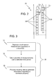
- FIG. 3 is a flow chart providing an exemplary method of estimating at least one property of an earth formation
- FIG. 4 is a cross-sectional view of an underground formation model
- FIG. 5 is a top view of the underground formation model of FIG. 4 ;
- FIGS. 6A and 6B depict exemplary results of the inversion of gravity measurements taken with a single gravity sensor
- FIG. 7 depicts exemplary results of the inversion of vertical gradient of gravity measurements taken with a single gravity sensor
- FIGS. 8A and 8B depict exemplary results of the inversion of gravity measurements taken with the exemplary measurement assembly of FIG. 2 ;
- FIGS. 9A and 9B depict exemplary results of the inversion of gravity measurements taken with the exemplary measurement assembly of FIG. 2 ;
- FIG. 10 depicts data relating to displacements of gravity sensors estimated by the method of FIG. 3 ;
- FIG. 11 is a cross-sectional view of an underground formation model.
- an exemplary embodiment of a well logging, production and/or drilling system 10 includes a borehole string 11 that is shown disposed in a borehole 12 that penetrates at least one earth formation 14 during a drilling, well logging and/or hydrocarbon production operation.
- the string 11 includes a drill pipe, which may be one or more pipe sections or coiled tubing.
- the system 10 also includes a bottomhole assembly (BHA) 18 .
- a borehole fluid 16 such as a drilling or completion fluid or drilling mud may be pumped through the drillstring 11 , the BHA 18 and/or the borehole 12 .
- the BHA 18 or other portion of the borehole string 11 , includes a measurement assembly 20 configured to estimate at least one property of the formation 14 and/or the borehole 12 .
- the assembly 20 includes a data processing unit 22 for processing and/or presenting data related to the at least one property.
- the data processing unit 22 and/or the measurement assembly 20 is incorporated into or is in communication with a surface processing unit 24 .
- the BHA 18 and/or the measurement assembly 20 incorporates any of various transmission media and connections, such as wired connections, fiber optic connections, wireless connections and mud pulse telemetry.
- the data processing unit 22 and/or the surface processing unit 24 includes components as necessary to provide for storing and/or processing data collected from the assembly 20 .
- Exemplary components include, without limitation, at least one processor, storage, memory, input devices, output devices and the like.
- the data processing unit 22 and/or the surface processing unit 24 is configured as a control unit to control the operation of the measurement assembly and/or other components of the system 10 .
- the measurement assembly 20 includes a plurality of sensors 26 , each of which is displaced or offset from one another by a fixed distance “ ⁇ z”.
- the measurement assembly 20 is configured as a borehole absolute gravity meter with multiple sensors (BHGMMS), also referred to as a g-string or g-array.
- the g-array includes two or more absolute gravity sensors disposed in a common housing at fixed spacing between each other.
- the unknown and/or initial vertical displacement, or vertical component of the unknown displacement of the measurement assembly 20 over time, is shown as “ ⁇ h i ”.
- the vertical component has a direction that may be equal to the direction of gravity and/or a direction parallel to the major axis of the borehole.
- the displacement is also referred to as positioning error. Assuming that the offset between sensors is stable, the positioning error is the same for all multiple sensors.
- FIG. 3 illustrates a method 30 of estimating at least one property of an earth formation.
- the method 30 is used in conjunction with the measurement assembly 20 , the data processing unit 22 and/or the surface processing unit 24 , although the method 30 may be utilized in conjunction with any suitable combination of processors and sensors.
- the method 30 includes one or more stages 31 , 32 and 33 . In one embodiment, the method 30 includes the execution of all of stages 31 - 33 in the order described. However, certain stages may be omitted, stages may be added, or the order of the stages changed.
- the method 30 reduces or eliminates the positioning error related to downhole measurements, such as due to displacement ⁇ h of a sensor over time, which results in unknown positioning errors of the sensors 26 associated with repeated measurements.
- the method described herein utilizes any sensor assembly or apparatus that includes multiple sensors 26 positioned relative to one another at a fixed offset. In one embodiment, the fixed offset is along the vertical direction.
- the methods described herein are utilized with exemplary gravity sensors, the methods are not limited to such sensors.
- Other types of sensors may also be utilized, such as nuclear magnetic resonance (NMR) sensors, resistivity sensors, porosity sensors, gamma ray sensors, seismic receivers, acoustic imagers and others.
- NMR nuclear magnetic resonance
- Such sensors are utilized, for example, in logging processes such as wireline logging, measurement-while-drilling (MWD) and logging-while-drilling (LWD) processes.
- a multi-sensor measurement apparatus such as the measurement assembly 20 is disposed in the borehole 12 .
- the apparatus may be lowered into the borehole via any suitable conveyance, such as the borehole string 11 or a wireline.
- the sensors 26 are absolute gravity sensors.
- a plurality of measurements “M” are taken over a selected time period.
- Each measurement “M” includes a measurement from each sensor 26 at a selected point in time.
- Each measurement is separately temporally by a selected period of time.
- the multi-sensor gravimeter includes a number “N” of gravity sensors positioned at fixed offsets. The total number of gravity measurements is thus equal to N*M.
- two sequential time-lapse measurements (“No 1” and “No 2”) are taken by the plurality of gravity sensors in a multi-sensor gravimeter or g-array.
- data received from the measurement apparatus is processed to generate information regarding at least one property of the formation 14 .
- the property information is estimated by solving an inverse problem to construct a model of the at least one property.
- gravity data is inverted to generate values of differential density and values of displacements.
- Such information is useful in observing density variations caused by the movement of gas ⁇ water contact, and in measuring fluid motion within a reservoir. Such variations can be estimated from the inverse problem solution for differential borehole gravity data.
- processing the data includes applying a multi-sensor positioning correction (MSPC) to the data obtained from a multi-sensor measurement apparatus such as the measurement assembly 20 that includes the borehole sensors 26 .
- the MSPC applies an inversion to the gravity data.
- Different approaches can be implemented to invert gravity data (Tikhonov regularization, Kalman filters, principal component inversion, etc.)
- ⁇ is an arbitrary property of a medium or component of interest (such as an earth formation)
- G is the vector of the arbitrary geophysical field related to the arbitrary property
- A is the forward problem matrix.
- the elements of Matrix B such as in the case of gravity, determine the impact of a unit displacement of the multi-sensor tool on the measured arbitrary geophysical field.
- the inversion described herein does not depend on data contents, and accordingly, any type of data may be used.
- Examples of such data include data resulting from various measurements taken of formation and/or borehole properties using surface sensors and/or sensors positioned within the borehole, as well as measurements relating to downhole or surface components of various well logging, production and/or drilling devices and systems.
- Examples of such measurements include formation and/or fluid sample measurements, formation evaluation measurements such as resistivity and nuclear magnetic resonance (NMR) measurements, and drilling or production measurements such as fluid temperature and fluid flow rates.
- NMR nuclear magnetic resonance
- the data utilized in the systems, devices and methods described herein are not limited to the specific data types described herein.
- the value of density is treated as a priori information. Different types of density logging can be used to provide each borehole gravity station with an appropriate density value.
- utilization of the modified functional (2) can be used not only for finding unknown anomalous densities, but also for estimating the gravimeter positioning error ⁇ g for any two repeated measurements.
- the algorithm described herein enables users to determine unknown displacements due to repeated positioning of the set of sensors. The more sensors involved in measurements, the smaller the random error of each gravity sensor is, and the higher the accuracy that can be achieved when these displacements are determined.
- FIGS. 4 and 5 an example of the method 30 described herein is shown in conjunction with a synthetic underground formation model 40 .
- a cross-sectional view of the sensor configuration used to generate the model 40 is shown in FIG. 4 .
- the configuration includes a plurality of boreholes 42 drilled into the formation 14 .
- the multi-sensor measurement assembly 20 is used to measure gravity at a plurality of locations 44 between the surface and the gas/saturated water layer. within each borehole.
- a relatively thin, inclined petroleum reservoir 46 is also shown.
- the reservoir is rectangular in a top view, as seen in FIG. 5 , and has a length “L” and a width “W”.
- FIG. 5 shows a top view of the reservoir 14 and the boreholes 42 , and also shows the distribution of density in the reservoir model at a fixed point of time during the gravity survey, shown by areas designated as numerals, 48 , 50 , 52 , 54 , 56 , 58 , 60 and 62 .
- the model is a three-dimensional model having orthogonal axes x, y and z. In this model, the z-axis extends in the vertical direction.
- the model includes a plurality of selected true values of density that are correlated to corresponding grids cells to form a selected density distribution that is to be estimated by the inversion algorithm using the measurement assembly 20 .
- the true values of density are fixed while the inversion algorithm is run.
- Notations and values of model parameters are shown in the following table:
- the location of water/gas contact is simulated by anomalous density changes in discrete elements of the reservoir. Expected changes in the anomalous gravity field reflect changes in reservoir fluid densities. The results described are based on forward/inverse gravity modeling for the model shown in FIGS. 4-5 .
- FIGS. 6-10 illustrate three types of gravity measurements: borehole gravity measurements taken with a single absolute gravity sensor at a single location, vertical gradient of the borehole gravity measurements taken with the single sensor, and absolute borehole gravity measurements taken with a multi-sensor gravimeter such as the measurement assembly 20 .
- the gravity sensors are absolute and/or relative gravimeters.
- An absolute gravimeter measures the actual value of g with a precision of, for example, about 1 ⁇ Gal.
- a relative gravimeter measures relative changes in g with a certain precision, such as about 10 ⁇ Gal in about 5 min.
- the relative gravity measurements are tied to the absolute gravity network.
- Vertical gradient sensors are configured to estimate a vertical gradient of gravity between the end points of interval “ ⁇ H” by continuously or intermittently measuring the gravitational field as the sensors are moved vertically between the interval ⁇ H.
- a “vertical gradient” of borehole gravity, for a vertical borehole interval, is the ratio of the gravity differences to the height differences as measured between the end points of the interval.
- FIGS. 6A and 6B the density distribution results for solving the inverse problem of borehole gravity measurements using a single sensor are shown.
- the Gaussian random noise ⁇ 0 in the signal of gravity sensor is assumed to have values of 0, 1 and 3 ⁇ Gal.
- the uncertainty ⁇ h i in the location of the sensor when repeated measurements are conducted is assumed to have values of 0, 5, 10 and 15 cm, which is equivalent to an additional random noise ⁇ l of 0, 5, 10, and 15 ⁇ Gal.
- the water-gas transient contact zone is bounded approximately by the 0.017 g/cc density isoline, and is denoted as boundary 64 .
- the inversion using a single gravity sensor produces a relatively good approximation of the original density distribution (error equals zero) for errors ⁇ ⁇ ⁇ 1-3 ⁇ Gal.
- accuracy of the solution to the inverse problem gets worse as the noise level increases.
- the smoothing image provides some information about the location of the boundary, but the image is diffused and unfocused.
- the inverted differential density shows a poor resolution if ⁇ ⁇ ⁇ 1.4 ⁇ Gal. For such errors, the zone of inverted anomalous density loses its connectedness, and thus no boundary can be practically tracked.
- the density distribution results are shown for solving the inverse problem for gravity measurements using the multi-sensor gravimeter.
- the results are shown in FIGS. 8A and 8B for uncertainties ⁇ h i (in the location of all nine sensors) of 0 and 5 cm respectively, and in FIGS. 9A and 9B for uncertainties of 10 and 15 cm respectively.
- FIGS. 8A-B and 9 A-B none of the images are diffused, and for all cases considered, the gas/water contact boundary can be revealed and tracked.
- this method utilizing a multi-sensor measurement assembly as described herein is advantageous over conventional gravity measurements.
- FIG. 10 illustrates the capability of the method to generate not only density distribution data but also unknown displacements ⁇ h i .
- FIG. 10 includes data from multiple gravity stations at various locations in an exemplary borehole. The locations of the multi-sensor gravimeter measurements are identified by station number and each has an original displacement in a borehole represented by curve 64 . Displacements are defined as Gaussian random quantities with zero mean. Therefore different values of displacements have been assigned to all gravity stations in all boreholes. The data retrieved from the gravimeters is incorporated into functional equation (2).
- FIG. 10 also includes recovered displacements 66 obtained through the inversion with the method 30 , and the difference 68 between the original and inverted displacements. All these results show a good capability of MSPC inversion to perform a positioning correction.
- the model includes two masses m and M situated in free space having orthogonal axes x, y and z.
- the z-axis extends in the vertical direction.
- the mass m is located at location P having coordinates (0, y 1 , z 1 ).
- the mass m begins to shift and at t ⁇ t 2 reaches a fixed position in the point Q with the coordinates (0, y 2 , z 2 ).
- the mass M is located in the point S with the time-independent coordinates (0, y 0 , z 0 ) and satisfies the condition that the gravity field of the mass M is by several orders of magnitude greater than the field created by the mass m, i.e., M>>>m.
- Initial measurements are performed at t ⁇ t 1 and again at t ⁇ t 2 using a measuring system located on the z-axis.
- the gravity field of the mass M corresponds to the Earth's normal field, and the field of the mass m, to the anomalous gravity field created due to the moving water-gas contact.
- the measuring system models the time-lapse borehole observations of the gravity field.
- the problem under consideration contains only two desired unknowns ⁇ y 2,1 , ⁇ z 2,1 . If the number of observation points N>>2, then for a set of N values of the differential gravity field ⁇ g z , the estimate for ⁇ y 2,1 , ⁇ z 2,1 can be obtained, e.g., using the least square method or any other suitable approach.
- the method 30 described herein provides a solution to this difficulty.
- the multi-sensor gravimeter generates not one but M values of the borehole gravity field for each position of the gravity meter in the borehole. It should be noted that, at a fixed position of the gravity meter, each of these M measurements will have the same positioning error. Thus, the number of unknowns remains the same: N+2, but the number of equations increases to N ⁇ M. These additional equations allow estimates of all unknown parameters to be obtained, including N values of the tool displacement due to re-positioning.
- borehole or “wellbore” refers to a single hole that makes up all or part of a drilled well.
- “formations” refer to the various features and materials that may be encountered in a subsurface environment. Accordingly, it should be considered that while the term “formation” generally refers to geologic formations of interest, that the term “formations,” as used herein, may, in some instances, include any geologic points or volumes of interest (such as a survey area) including the fluids contained therein. Furthermore, various drilling or completion service tools may also be contained within this borehole or wellbore, in addition to formations.
- “drillstring” or “string” as used herein refers to any structure or carrier suitable for lowering a tool through a borehole or connecting a drill bit to the surface, and is not limited to the structure and configuration described herein.
- the borehole string 11 is configured as a hydrocarbon production string or formation evaluation string.
- the assembly 20 is described as being disposed in or in communication with a borehole, the assembly 20 is not limited. The assembly 20 may be utilized for any desired surface or downhole pressure measurement and may be incorporated into or disposed with any suitable carrier.
- carrier means any device, device component, combination of devices, media and/or member that may be used to convey, house, support or otherwise facilitate the use of another device, device component, combination of devices, media and/or member.
- exemplary non-limiting carriers include drill strings of the coiled tube type, of the jointed pipe type and any combination or portion thereof.
- Other carrier examples include casing pipes, wirelines, wireline sondes, slickline sondes, drop shots, downhole subs, BHA's, drill string.
- the apparatus and methods described herein provide various advantages over prior art techniques.
- the apparatus and method provide a reliable solution for estimating errors in measurement data due to sensor positioning errors, and thus provide for more repeatable measurements than available with prior art devices and methods.
- Such repeatability is of a primary importance for 4D borehole gravity surveys, i.e., three-dimensional gravity surveys that are repeated over time, because at two successive points of time it is unlikely to locate an instrument at the same location.
- various analyses and/or analytical components may be used, including digital and/or analog systems.
- the system may have components such as a processor, storage media, memory, input, output, communications link (wired, wireless, pulsed mud, optical or other), user interfaces, software programs, signal processors (digital or analog) and other such components (such as resistors, capacitors, inductors and others) to provide for operation and analyses of the apparatus and methods disclosed herein in any of several manners well-appreciated in the art.
- teachings may be, but need not be, implemented in conjunction with a set of computer executable instructions stored on a computer readable medium, including memory (ROMs, RAMs), optical (CD-ROMs), or magnetic (disks, hard drives), or any other type that when executed causes a computer to implement the method of the present invention.
- ROMs, RAMs random access memory
- CD-ROMs compact disc-read only memory
- magnetic (disks, hard drives) any other type that when executed causes a computer to implement the method of the present invention.
- These instructions may provide for equipment operation, control, data collection and analysis and other functions deemed relevant by a system designer, owner, user or other such personnel, in addition to the functions described in this disclosure.
- a sample line, sample storage, sample chamber, sample exhaust, pump, piston, power supply e.g., at least one of a generator, a remote supply and a battery
- vacuum supply e.g., at least one of a generator, a remote supply and a battery
- refrigeration i.e., cooling
- heating component e.g., heating component
- motive force such as a translational force, propulsional force or a rotational force
- magnet electromagnet
- sensor electrode
- transmitter, receiver, transceiver e.g., transceiver
- controller e.g., optical unit, electrical unit or electromechanical unit
Landscapes
- Physics & Mathematics (AREA)
- Life Sciences & Earth Sciences (AREA)
- General Life Sciences & Earth Sciences (AREA)
- General Physics & Mathematics (AREA)
- Geophysics (AREA)
- Geophysics And Detection Of Objects (AREA)
- Testing Or Calibration Of Command Recording Devices (AREA)
- Investigating Or Analyzing Materials By The Use Of Electric Means (AREA)
Abstract
Description
Φ(σ)=∥Aσ−G∥ 2, (1)
where “σ” are the unknown anomalous densities (which may indicate water/gas contact locations), “G” is the vector of the gravity measured downhole, and “A” is a forward problem matrix. Different approaches can be implemented to invert gravity data (Tikhonov regularization, Kalman filters, principal component inversion, etc.)
Φ(σ,Δh)=∥Aσ+BΔh−G∥ 2 (2)
Here “Δh” is a vector of length M, containing elements Δhk. Matrix “B” elements determine the impact of a unit displacement on the measured gravity field, and they have this form:
The function K depends on the vertical gradient of the gravity field, and also on variations in the density of the medium in which the gravity measurements are performed. In a particular case of a homogeneous medium of density ρ the function K has this simple representation:
K=308.6−83.84ρ
where the number 308.6 is a value of the normal gradient.
| Parameter | Notation | Value |
| Depth of reservoir upper edge [m] | Htop | 2610 | |||
| Depth of reservoir lower edge [m] | Hbottom | 3820 | |||
| Simulation grid square cell size [m] | Dcell | 100 | |||
| Anomalous density distribution (g/cc) | 48-62 | 0.002-0.037 | |||
| |
42 | ||||
| Distance between | Dgz | 20 | |||
| stations [m] | |||||
| Number of borehole gravity stations | Nst | 51 | |||
| Gaussian random noise for | δ | 0 | 0, 1, 3 | ||
| μGal] | δl | ||||
| Precisions of the repeated location of the | ±0, 5, 10, 15 | ||||
| borehole gravity meter [cm] | |||||
Δy 2,1 =y 2 −y 1 , Δz 2,1 =z 2 −z 1, (3)
z B,i =z A,i +Δz i , i=1, . . . , N (4)
It is known that the gravity field of each of the masses mentioned has the following form on the z-axis:
Due to the superposition principle, the total gravity field gz measured on the z-axis can be written out as following:
g z(z,t 1)=g z,M(z)+g z,m(z,t 1)
g z(z,t 2)=g z,M(z)+g z,m(z,t 2) (8)
Δg z =g z(z,t 2)−g z(z,t 1). (9)
This equation can be re-written as follows:
Δg z=(g z,m(z B ,t 2)−g z,m(z A ,t 1))+(g z,M(z B ,t 2)−g z,M(z A ,t 1)) (10)
Claims (25)
Φ(σ,Δh)=∥Aσ+BΔh−G∥ 2,
Φ(σ,Δh)=∥Aσ+BΔh−G∥ 2,
Φ(σ,Δh)=∥Aσ+BΔh−G∥ 2,
Priority Applications (1)
| Application Number | Priority Date | Filing Date | Title |
|---|---|---|---|
| US12/777,511 US8738293B2 (en) | 2009-05-11 | 2010-05-11 | Apparatus and method for multi-sensor estimation of a property of an earth formation |
Applications Claiming Priority (2)
| Application Number | Priority Date | Filing Date | Title |
|---|---|---|---|
| US17704309P | 2009-05-11 | 2009-05-11 | |
| US12/777,511 US8738293B2 (en) | 2009-05-11 | 2010-05-11 | Apparatus and method for multi-sensor estimation of a property of an earth formation |
Publications (2)
| Publication Number | Publication Date |
|---|---|
| US20100286967A1 US20100286967A1 (en) | 2010-11-11 |
| US8738293B2 true US8738293B2 (en) | 2014-05-27 |
Family
ID=43062880
Family Applications (1)
| Application Number | Title | Priority Date | Filing Date |
|---|---|---|---|
| US12/777,511 Expired - Fee Related US8738293B2 (en) | 2009-05-11 | 2010-05-11 | Apparatus and method for multi-sensor estimation of a property of an earth formation |
Country Status (5)
| Country | Link |
|---|---|
| US (1) | US8738293B2 (en) |
| BR (1) | BRPI1010645A2 (en) |
| GB (1) | GB2482097B (en) |
| NO (1) | NO343620B1 (en) |
| WO (1) | WO2010132432A2 (en) |
Families Citing this family (25)
| Publication number | Priority date | Publication date | Assignee | Title |
|---|---|---|---|---|
| EP2361414A2 (en) * | 2008-10-09 | 2011-08-31 | Chevron U.S.A. Inc. | Iterative multi-scale method for flow in porous media |
| US8681178B1 (en) | 2010-11-02 | 2014-03-25 | Google Inc. | Showing uncertainty in an augmented reality application |
| US9651708B2 (en) * | 2011-04-21 | 2017-05-16 | Baker Hughes Incorporated | Method of mapping reservoir fluid movement using gravity sensors |
| WO2013036156A1 (en) * | 2011-09-07 | 2013-03-14 | Baker Hughes Incorporated | Apparatus and method for estimating geologic boundaries |
| US10429537B2 (en) | 2012-01-30 | 2019-10-01 | Schlumberger Technology Corporation | Efficiency of pixel-based inversion algorithms |
| US9140085B2 (en) | 2012-02-14 | 2015-09-22 | Baker Hughes Incorporated | Apparatus and method for positioning and orienting a borehole tool |
| US9939551B2 (en) | 2012-09-24 | 2018-04-10 | Schlumberger Technology Corporation | Systems, devices and methods for borehole gravimetry |
| US9201155B2 (en) | 2013-06-12 | 2015-12-01 | Halliburton Energy Services, Inc. | Systems and methods for downhole electromagnetic field measurement |
| US9291740B2 (en) | 2013-06-12 | 2016-03-22 | Halliburton Energy Services, Inc. | Systems and methods for downhole electric field measurement |
| US9250350B2 (en) | 2013-06-12 | 2016-02-02 | Halliburton Energy Services, Inc. | Systems and methods for downhole magnetic field measurement |
| EP3094997B1 (en) * | 2014-01-14 | 2020-12-16 | Baker Hughes Holdings LLC | A method for detecting fluid fronts using a combination of electric and gravity measurements in boreholes |
| US20170111112A1 (en) * | 2014-06-25 | 2017-04-20 | Halliburton Energy Services, Inc. | Optically Obtaining Gravitational Field Measurements in a Downhole or Subsea Environment |
| US20170090063A1 (en) * | 2014-06-25 | 2017-03-30 | Halliburton Energy Services, Inc. | Methods and Systems for Permanent Gravitational Field Sensor Arrays |
| US10108762B2 (en) | 2014-10-03 | 2018-10-23 | International Business Machines Corporation | Tunable miniaturized physical subsurface model for simulation and inversion |
| WO2016123014A1 (en) * | 2015-01-26 | 2016-08-04 | Schlumberger Technology Corporation | Method for determining formation properties by inversion of multisensor wellbore logging data |
| BR112017014331A2 (en) * | 2015-03-30 | 2018-03-06 | Halliburton Energy Services Inc | method, apparatus and system |
| EP3298379A1 (en) * | 2015-05-20 | 2018-03-28 | Saudi Arabian Oil Company | Sampling techniques to detect hydrocarbon seepage |
| EP3171203B1 (en) * | 2015-11-18 | 2019-01-02 | CGG Services SAS | Adaptive ensemble-based method and device for highly-nonlinear problems |
| US10408964B2 (en) * | 2015-12-18 | 2019-09-10 | Schlumberger Technology Corporation | Multiple detector NMR tool system and inversion methods for NMR logging |
| NO20211442A1 (en) * | 2019-07-29 | 2021-11-26 | Landmark Graphics Corp | Gas saturation distribution monitoring in hydrocarbon reservoir |
| US11668847B2 (en) | 2021-01-04 | 2023-06-06 | Saudi Arabian Oil Company | Generating synthetic geological formation images based on rock fragment images |
| US20230063340A1 (en) * | 2021-08-27 | 2023-03-02 | Halliburton Energy Services, Inc. | System and method of drilling a wellbore using wellbore and surface gravity sensing |
| WO2023034875A1 (en) | 2021-08-31 | 2023-03-09 | Saudi Arabian Oil Company | Quantitative hydraulic fracturing surveillance from fiber optic sensing using machine learning |
| CN115961950B (en) * | 2023-02-03 | 2024-06-25 | 西南石油大学 | Method for predicting lower limit of drilling fluid density under water rock action based on rock acoustic information |
| CN118208227B (en) * | 2024-05-16 | 2024-07-23 | 山东九商定向钻探有限公司 | Directional drilling measurement analysis method based on electromagnetic waves |
Citations (6)
| Publication number | Priority date | Publication date | Assignee | Title |
|---|---|---|---|---|
| US5821413A (en) | 1997-04-10 | 1998-10-13 | Atlantic Richfield Company | Gravity gradiometry in a wellbore using a virtual long-baseline |
| US20030220750A1 (en) * | 2002-05-24 | 2003-11-27 | Jean-Perre Delhomme | methods for monitoring fluid front movements in hydrocarbon reservoirs using permanent sensors |
| US20040250614A1 (en) * | 2003-03-21 | 2004-12-16 | Ander Mark E. | Gravity techniques for drilling and logging |
| US20050269082A1 (en) | 2004-06-07 | 2005-12-08 | Pathfinder Energy Services, Inc. | Control method for downhole steering tool |
| US20080295594A1 (en) | 2007-03-22 | 2008-12-04 | Scintrex Limited | Method and apparatus for measurements of gravity in small diameter boreholes |
| US20090223291A1 (en) | 2007-09-28 | 2009-09-10 | Schlumberger Technology Corporation | Gravity measurment methods for monitoring reservoirs |
-
2010
- 2010-05-11 WO PCT/US2010/034367 patent/WO2010132432A2/en not_active Ceased
- 2010-05-11 BR BRPI1010645A patent/BRPI1010645A2/en active Search and Examination
- 2010-05-11 GB GB1120161.3A patent/GB2482097B/en not_active Expired - Fee Related
- 2010-05-11 US US12/777,511 patent/US8738293B2/en not_active Expired - Fee Related
-
2011
- 2011-11-04 NO NO20111516A patent/NO343620B1/en not_active IP Right Cessation
Patent Citations (6)
| Publication number | Priority date | Publication date | Assignee | Title |
|---|---|---|---|---|
| US5821413A (en) | 1997-04-10 | 1998-10-13 | Atlantic Richfield Company | Gravity gradiometry in a wellbore using a virtual long-baseline |
| US20030220750A1 (en) * | 2002-05-24 | 2003-11-27 | Jean-Perre Delhomme | methods for monitoring fluid front movements in hydrocarbon reservoirs using permanent sensors |
| US20040250614A1 (en) * | 2003-03-21 | 2004-12-16 | Ander Mark E. | Gravity techniques for drilling and logging |
| US20050269082A1 (en) | 2004-06-07 | 2005-12-08 | Pathfinder Energy Services, Inc. | Control method for downhole steering tool |
| US20080295594A1 (en) | 2007-03-22 | 2008-12-04 | Scintrex Limited | Method and apparatus for measurements of gravity in small diameter boreholes |
| US20090223291A1 (en) | 2007-09-28 | 2009-09-10 | Schlumberger Technology Corporation | Gravity measurment methods for monitoring reservoirs |
Non-Patent Citations (3)
| Title |
|---|
| Last, B. J. and K. Kubik, "Compact Gravity Inversion," Geophysics, vol. 48, No. 6, Jun. 1983, pp. 713-721. |
| Notification of Transmittal of the International Search Report and the Written Opinion of the International Searching Authority, or the Declaration; PCT/US2010/034367; Jan. 26, 2011. |
| Portniaguine, Oleg and Michael S. Zhdanov, "Focusing Geophysical Inversion Images," Geophysics, vol. 64, No. 3, May-Jun. 1999, pp. 874-887. |
Also Published As
| Publication number | Publication date |
|---|---|
| WO2010132432A2 (en) | 2010-11-18 |
| NO20111516A1 (en) | 2011-11-22 |
| WO2010132432A3 (en) | 2011-03-31 |
| US20100286967A1 (en) | 2010-11-11 |
| NO343620B1 (en) | 2019-04-15 |
| GB201120161D0 (en) | 2012-01-04 |
| GB2482097B (en) | 2013-09-11 |
| GB2482097A (en) | 2012-01-18 |
| BRPI1010645A2 (en) | 2016-03-15 |
Similar Documents
| Publication | Publication Date | Title |
|---|---|---|
| US8738293B2 (en) | Apparatus and method for multi-sensor estimation of a property of an earth formation | |
| US11346833B2 (en) | Reservoir fluid characterization system | |
| US8700372B2 (en) | Method for 3-D gravity forward modeling and inversion in the wavenumber domain | |
| US10445669B2 (en) | System and method for mapping reservoir properties away from the wellbore | |
| US10324212B2 (en) | Prediction ahead of bit using vertical seismic profile data and global inversion | |
| US10329903B2 (en) | Methods of characterizing earth formations using physiochemical model | |
| US8744817B2 (en) | Method for upscaling a reservoir model using deep reading measurements | |
| CN101278209B (en) | Method and system for pre-drill pore pressure prediction | |
| US20180058211A1 (en) | Joint inversion of downhole tool measurements | |
| US9341739B2 (en) | Apparatus and method for estimating geologic boundaries | |
| US9696441B2 (en) | Apparatus and method for predicting vertical stress fields | |
| US9316761B2 (en) | Determining reservoir connectivity using fluid contact gravity measurements | |
| EP1606656A2 (en) | Gravity techniques for drilling and logging | |
| US20110098996A1 (en) | Sifting Models of a Subsurface Structure | |
| US9651708B2 (en) | Method of mapping reservoir fluid movement using gravity sensors | |
| CN113126149B (en) | Method and system for seismic image processing to enhance geological structure fidelity | |
| EP3791216B1 (en) | Geologic formation neutron porosity system | |
| US20260072189A1 (en) | Passive source seismic re-datuming/positioning and deconvolution for sub-surface imaging | |
| Дашевский | Gravity monitoring at oil and gas fields: data inversion and errors | |
| Gallagher | AAPG/Datapages Discovery Series No. 7: Multidimensional Basin Modeling, Chapter 2: Modeling Thermal Histories: How Important Are Thermal Conductivity Data? | |
| QUANTIFY et al. | Contract Date: Sept. 29, 1993 Anticipated Completion: Sept. 30, 1996 |
Legal Events
| Date | Code | Title | Description |
|---|---|---|---|
| AS | Assignment |
Owner name: BAKER HUGHES INCORPORATED, TEXAS Free format text: ASSIGNMENT OF ASSIGNORS INTEREST;ASSIGNORS:VASILEVSKIY, ALEXANDR N.;DASHEVSKY, YULIY A.;GEORGI, DANIEL T.;REEL/FRAME:024730/0046 Effective date: 20100518 |
|
| AS | Assignment |
Owner name: THE BANK OF NOVA SCOTIA, CANADA Free format text: SECURITY AGREEMENT;ASSIGNORS:ASHLAND LICENSING AND INTELLECTUAL PROPERTY LLC;HERCULES INCORPORATED;ISP INVESTMENTS INC.;REEL/FRAME:028318/0632 Effective date: 20120522 |
|
| AS | Assignment |
Owner name: THE BANK OF NOVA SCOTIA, CANADA Free format text: SECURITY AGREEMENT;ASSIGNORS:ASHLAND LICENSING AND INTELLECTUAL PROPERTY LLC;ISP INVESTMENTS INC.;REEL/FRAME:028397/0338 Effective date: 20120611 |
|
| AS | Assignment |
Owner name: ASHLAND INC., OHIO Free format text: RELEASE BY SECURED PARTY;ASSIGNOR:THE BANK OF NOVA SCOTIA;REEL/FRAME:028572/0659 Effective date: 20120716 |
|
| AS | Assignment |
Owner name: ASHLAND LICENSING AND INTELLECTUAL PROPERTY LLC, OHIO Free format text: RELEASE OF PATENT SECURITY AGREEMENT;ASSIGNOR:THE BANK OF NOVA SCOTIA;REEL/FRAME:030025/0320 Effective date: 20130314 Owner name: ISP INVESTMENTS INC., DELAWARE Free format text: RELEASE OF PATENT SECURITY AGREEMENT;ASSIGNOR:THE BANK OF NOVA SCOTIA;REEL/FRAME:030025/0320 Effective date: 20130314 Owner name: HERCULES INCORPORATED, DELAWARE Free format text: RELEASE OF PATENT SECURITY AGREEMENT;ASSIGNOR:THE BANK OF NOVA SCOTIA;REEL/FRAME:030025/0320 Effective date: 20130314 Owner name: AQUALON COMPANY, DELAWARE Free format text: RELEASE OF PATENT SECURITY AGREEMENT;ASSIGNOR:THE BANK OF NOVA SCOTIA;REEL/FRAME:030025/0320 Effective date: 20130314 Owner name: ASHLAND LICENSING AND INTELLECTUAL PROPERTY LLC, O Free format text: RELEASE OF PATENT SECURITY AGREEMENT;ASSIGNOR:THE BANK OF NOVA SCOTIA;REEL/FRAME:030025/0320 Effective date: 20130314 |
|
| STCF | Information on status: patent grant |
Free format text: PATENTED CASE |
|
| MAFP | Maintenance fee payment |
Free format text: PAYMENT OF MAINTENANCE FEE, 4TH YEAR, LARGE ENTITY (ORIGINAL EVENT CODE: M1551) Year of fee payment: 4 |
|
| FEPP | Fee payment procedure |
Free format text: MAINTENANCE FEE REMINDER MAILED (ORIGINAL EVENT CODE: REM.); ENTITY STATUS OF PATENT OWNER: LARGE ENTITY |
|
| LAPS | Lapse for failure to pay maintenance fees |
Free format text: PATENT EXPIRED FOR FAILURE TO PAY MAINTENANCE FEES (ORIGINAL EVENT CODE: EXP.); ENTITY STATUS OF PATENT OWNER: LARGE ENTITY |
|
| STCH | Information on status: patent discontinuation |
Free format text: PATENT EXPIRED DUE TO NONPAYMENT OF MAINTENANCE FEES UNDER 37 CFR 1.362 |
|
| FP | Lapsed due to failure to pay maintenance fee |
Effective date: 20220527 |