US8730388B2 - Wearable video camera with dual rotatable imaging devices - Google Patents
Wearable video camera with dual rotatable imaging devices Download PDFInfo
- Publication number
- US8730388B2 US8730388B2 US13/204,242 US201113204242A US8730388B2 US 8730388 B2 US8730388 B2 US 8730388B2 US 201113204242 A US201113204242 A US 201113204242A US 8730388 B2 US8730388 B2 US 8730388B2
- Authority
- US
- United States
- Prior art keywords
- image
- lateral
- barrel
- accessory
- longitudinal
- Prior art date
- Legal status (The legal status is an assumption and is not a legal conclusion. Google has not performed a legal analysis and makes no representation as to the accuracy of the status listed.)
- Expired - Fee Related, expires
Links
Images


Classifications
-
- H—ELECTRICITY
- H04—ELECTRIC COMMUNICATION TECHNIQUE
- H04N—PICTORIAL COMMUNICATION, e.g. TELEVISION
- H04N23/00—Cameras or camera modules comprising electronic image sensors; Control thereof
- H04N23/90—Arrangement of cameras or camera modules, e.g. multiple cameras in TV studios or sports stadiums
-
- H—ELECTRICITY
- H04—ELECTRIC COMMUNICATION TECHNIQUE
- H04N—PICTORIAL COMMUNICATION, e.g. TELEVISION
- H04N5/00—Details of television systems
- H04N5/76—Television signal recording
- H04N5/765—Interface circuits between an apparatus for recording and another apparatus
- H04N5/77—Interface circuits between an apparatus for recording and another apparatus between a recording apparatus and a television camera
-
- H—ELECTRICITY
- H04—ELECTRIC COMMUNICATION TECHNIQUE
- H04N—PICTORIAL COMMUNICATION, e.g. TELEVISION
- H04N23/00—Cameras or camera modules comprising electronic image sensors; Control thereof
- H04N23/45—Cameras or camera modules comprising electronic image sensors; Control thereof for generating image signals from two or more image sensors being of different type or operating in different modes, e.g. with a CMOS sensor for moving images in combination with a charge-coupled device [CCD] for still images
-
- H—ELECTRICITY
- H04—ELECTRIC COMMUNICATION TECHNIQUE
- H04N—PICTORIAL COMMUNICATION, e.g. TELEVISION
- H04N5/00—Details of television systems
- H04N5/76—Television signal recording
- H04N5/907—Television signal recording using static stores, e.g. storage tubes or semiconductor memories
Definitions
- the present invention relates generally to digital video cameras. More particularly, the present invention relates to wearable or point-of-view (POV) digital cameras.
- POV point-of-view
- Hands-free video recording and/or action videography/videotography can involve the use of a camera mounted on a user, such as a user's helmet and often referred to as a helmet cam.
- a camera mounted on a user such as a user's helmet and often referred to as a helmet cam.
- a helmet cam For example, see the GoPro HD helmet Hero digital camera.
- Such cameras can be bulky and awkward, and can require elaborate, bulky and awkward mounting hardware, as the entire camera is mounted to the helmet.
- such cameras may be limited in their mountability, e.g. only being mountable to a helmet.
- Other systems can use a remote camera or remote recorder.
- V.I.O. POV.HD camera and US Patent Publication Nos. 2008/0192114; 2009/0109292 and 2010/0103267.
- Such cameras can also be bulky and awkward to mount and use.
- So called “spy” cameras have a digital camera build into a pair of conspicuous and overwhelming glasses.
- the invention provides a digital imaging device including at least two image sensors carried by a body, and each capable of converting an optical image into an electrical signal.
- the at least two image sensors have image axes oriented transverse to one another and face in different directions transverse to one another.
- the at least two image sensors are rotatable with respect to the body and each has a rotational axis parallel with a respective corresponding image axis.
- Each image sensor has an upright physical orientation corresponding to an upright orientation of the optical image, and is capable of rotation about the rotational axis to orient the image sensor in the upright orientation.
- the invention provides a digital image recording system including an elongated barrel defining a longitudinal axis.
- a longitudinal ferrule is rotatably disposed on an end of the barrel, and has a rotational axis parallel with the longitudinal axis of the barrel.
- a longitudinal image sensor is carried by the longitudinal ferrule at the end of the barrel, and has an image axis parallel with the rotational axis of the longitudinal ferrule and the longitudinal axis of the barrel.
- a lateral ferrule is rotatably disposed on a side of the barrel, and has a rotational axis transverse to the longitudinal axis of the barrel.
- a lateral image sensor is carried by the lateral ferrule on the side of the barrel, and has an image axis parallel with the rotational axis of the lateral ferrule and transverse to the longitudinal axis of the barrel.
- Each image sensor is capable of converting an optical image into an electrical signal.
- the system also includes attachment means for attaching a lateral attachment side of the barrel, opposite the lateral image sensor and the lateral ferrule, to a wearable article or accessory with the lateral attachment side facing the wearable article or accessory.
- Each image sensor has an upright physical orientation corresponding to an upright orientation of the optical image.
- Each ferrule, and thus each image sensor is rotatable with respect to the barrel to orient each image sensor in the upright orientation.
- the barrel, the ferrules and the image sensors have a plurality of selectable configurations, including: 1) a left side mount with a) the lateral attachment side of the barrel facing a left side of the wearable article or accessory, b) the longitudinal image sensor and the longitudinal ferrule facing forwardly with respect to the wearable article or accessory, c) the lateral image sensor and the lateral ferrule facing left with respect to the wearable article or accessory, and d) the longitudinal and lateral image sensors oriented upright; 2) a right side mount with a) the lateral attachment side of the barrel facing a right side of the wearable article or accessory, b) the longitudinal image sensor and the longitudinal ferrule facing forwardly with respect to the wearable article or accessory, c) the lateral image sensor and the lateral ferrule facing right with respect to the wearable article or accessory, and d) the longitudinal and lateral image sensors oriented upright; 3) a top mount with a) the lateral attachment side of the barrel facing a top side of the wearable article or accessory,
- the invention provides a method for digital image recording, including: 1) obtaining a digital imaging device having at least two separate and discrete image sensors disposed in ferrules carried by an elongated barrel defining a longitudinal axis with a longitudinal image sensor and a longitudinal ferrule being rotatably disposed on an end of the barrel and having an image axis and a rotational axis parallel with the longitudinal axis, and a lateral image sensor and lateral ferrule disposed on a side of the barrel and having an image axis and a rotational axis transverse to the longitudinal axis, each image sensor being capable of converting an optical image into an electrical signal and having an upright physical orientation corresponding to an upright orientation of the optical image, and with a lateral attachment side of the barrel opposite the lateral image sensor and lateral ferrule; 2) securing the lateral attachment side of the barrel to a wearable article or accessory with the lateral attachment side facing the wearable article or accessory, and orienting the barrel, and thus the image axes
- FIG. 1 a is a perspective view of a digital imaging device or camera in accordance with an embodiment of the present invention
- FIG. 1 b is a perspective view of the digital imaging device or camera of FIG. 1 a shown disposed on a wearable article or accessory, namely a hat (showing a left side mount with the digital imaging device shown on a left side of the hat; but with top and front mounts shown in dashed lines;
- a wearable article or accessory namely a hat (showing a left side mount with the digital imaging device shown on a left side of the hat; but with top and front mounts shown in dashed lines;
- FIG. 1 c is a side view of the digital imaging device or camera of FIG. 1 a shown disposed on the wearable article or accessory, namely the hat of FIG. 1 b (showing a right side mount with the digital imaging device shown on a right hand side);
- FIG. 1 d is a side view of the digital imaging device or camera of FIG. 1 a;
- FIG. 1 e is a bottom view of the digital imaging device or camera of FIG. 1 a;
- FIG. 1 f is a front view of the digital imaging device or camera of FIG. 1 a;
- FIG. 1 g is a detailed cross-sectional view of the digital imaging device or camera of FIG. 1 taken along line 1 g of FIG. 1 e;
- FIG. 1 h is a detailed cross-sectional view of the digital imaging device or camera of FIG. 1 a taken along line 1 h of FIG. 1 f;
- FIG. 1 i is a cross-sectional view of the digital imaging device or camera of FIG. 1 a taken along line 1 i of FIG. 1 d;
- FIG. 2 is a schematic perspective view of the digital imaging device or camera of FIG. 1 a shown with a wired digital video recorder and player system in accordance with an embodiment of the present invention
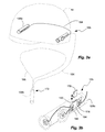
- FIG. 3 a is a schematic perspective view of a digital imaging device or camera shown with an external power source shown disposed on the hat (or with a lanyard in dashed lines) in accordance with an embodiment of the present invention
- FIG. 3 b is a schematic perspective view of a digital imaging device or camera shown with an internal power source and removable memory device in accordance with an embodiment of the present invention
- FIG. 4 a is a schematic perspective view of a digital imaging device or camera shown with a wireless digital video recorder and player system and on the hat in accordance with an embodiment of the present invention
- FIG. 4 b is a schematic perspective view of the digital imaging device or camera of FIG. 4 a;
- FIG. 5 is a perspective view of the digital imaging device or camera of FIG. 1 a shown disposed on a wearable article or accessory, namely glasses;
- FIG. 6 is a perspective view of the digital imaging device or camera of FIG. 1 a shown disposed on a wearable article or accessory, namely headphones;
- FIG. 7 is a perspective view of the digital imaging device or camera of FIG. 1 a shown disposed on a remote controllable base;
- FIG. 8 is a perspective view of the digital imaging device or camera of FIG. 1 a shown disposed in a hand held container.
- image sensor is used broadly herein to refer to a device that converts an optical or visual image into an electrical signal.
- Such an image sensor can include, by way of example, a charge-coupled device (CCD) or a complementary metal-oxide-semiconductor (CMOS) active pixel sensor, or other semiconductor image chip.
- CCD charge-coupled device
- CMOS complementary metal-oxide-semiconductor
- wearable article or accessory is used broadly herein to refer to an article or accessory wearable by a user.
- Such an article or accessory can include headgear, or can be wearable on the user's head, including by way of example, a helmet, a hat, a headband, eyeglasses, sun glasses, goggles, a headphone, and an earpiece.
- headgear can provide a point of view (POV) as the headgear moves with the user's head.
- POV point of view
- Such an article or accessory can also include clothing or a harness.
- Such a wearable article or accessory can have a front, a rear, a left side, a right side and a top; corresponding to a respective forward, rearward, left, right and upward point of view or direction with respect to the user.
- the present invention provides a digital imaging device or system capable of taking still or motion digital video images, and that is wearable by a user to capture point-of-view or action images in a hands-free manner, and that is easily attachable to the user or the user's clothing or accessories, and that is small and light weight.
- the digital imaging device can be used in many different activities, including by way of example, snowboarding, skiing, skate boarding, snowmobiling, mountain-biking, cross country cycling, climbing, golfing, horseback riding, ATVing, camping, fishing, amusement park rides, off-roading, camping, site-seeing, motorcycling, etc.
- the video recorded from these activities can be saved and viewed immediately, and relived later, and shared with friends and family.
- the present invention provides a digital imaging device with multiple image sensors oriented at different image directions to easily capture different views.
- the image sensors can be rotatable to facilitate mounting in different locations and orientations while allowing the image sensor(s) to be oriented upright.
- the image sensors can be rotated to obtain unique and interesting visual effects.
- a digital imaging device in an example implementation in accordance with the invention is shown with a wearable article or accessory, namely a hat 14 for purposes of illustration.
- the device 10 can include a body 18 that can be secured to the wearable article or accessory.
- the body 18 can take the form of an elongated barrel 22 having or defining a longitudinal axis 26 .
- the body or barrel can be cylindrical and annular and can be formed of plastic, such as by extrusion.
- the body or barrel can be formed of housing halves, such as by injection molding, and joined together, such as with adhesive or sonic welding. It will be appreciated that the body or barrel can have various different shapes, including cylindrical, rectangular block, etc.
- At least two image sensors are carried by the body or barrel, each capable of converting an optical image into an electrical signal.
- Multiple image sensors allows the device to capture different images.
- the image sensors can include a longitudinal image sensor 30 disposed at a longitudinal end of the body or barrel, and a lateral image sensor 34 disposed at a lateral side of the body or barrel. Having multiple image sensors on different sides of the body or barrel allows the body or barrel to be conveniently disposed on the wearable article or accessory.
- the image sensors can have image axes (longitudinal 38 and lateral 42 ) oriented transverse to one another, and facing (also indicated by arrows 38 and 42 ) in different directions transverse to one another. Having transverse image sensors allowed the device to capture different images from different directions.
- the at least two image sensors are rotatable (indicated by arrows 46 and 50 ) with respect to the body or barrel.
- Each image sensor has a rotational axis (also indicated by lines 38 and 42 ) parallel, or even concentric with, with a respective corresponding image axis 38 and 42 .
- the image sensor can pivot or rotate about the image axis, or image direction.
- Each image sensor has an upright physical orientation (indicated by arrows 54 and 58 ) corresponding to an upright orientation of the optical image (and an upright orientation of the display device or screen).
- the rotation of the image sensors allows the image sensors to be capable of rotation about the rotational axis to orient the image sensor in the upright orientation, despite the orientation of the body or barrel.
- the body or barrel can include ferrules to carry the image sensors and rotatably couple the image sensors to the body or barrel.
- a longitudinal ferrule 62 can be rotatably disposed on an end of the barrel 22 , and can have a rotational axis (also represented by line 38 ) parallel with, or even concentric with, the longitudinal axis 26 of the barrel.
- the longitudinal image sensor 30 can be carried by the longitudinal ferrule 62 at the end of the barrel 22 , and can have the image axis 38 parallel with the rotational axis 38 of the longitudinal ferrule and the longitudinal axis 22 of the barrel.
- a front end of the barrel can define an open front end, and the longitudinal ferrule can cover the open front end.
- a lateral ferrule 66 can be rotatably disposed on a side of the barrel 22 , and can have a rotational axis (also represented by line 42 ) transverse to the longitudinal axis 22 of the barrel.
- the lateral image sensor 34 can be carried by the lateral ferrule 66 on the side of the barrel 22 , and can have the image axis 42 parallel with the rotational axis of the lateral ferrule, and transverse to the longitudinal axis 22 of the barrel.
- the barrel can have a lateral tube or barrel extending from the side of the barrel with an opening therein covered by the lateral ferrule.
- the ferrules can be formed of plastic, such as by injection molding.
- the imaging sensors can be adhered to the inside of the ferrules, or can be held by a snap clip, or the like.
- Each ferrule can have an opening therein through which light can pass to impinge on the image sensor.
- the opening can form the aperture of a pin-hole camera.
- the opening can be formed by a bore through the ferrule.
- the opening can be covered by a transparent cover or lens (having optical power).
- the ferrules can be rotatably connected to the barrel in any appropriate manner.
- the openings in the barrel 22 can include an annular flange 70 extending inwardly.
- the ferrule 62 or 66 can have one or more fingers 74 extending in through the opening an engaging the flange 70 .
- the fingers can have an annular channel or groove 78 which receives the flange 70 so that the ferrule can rotate with respect to the barrel.
- a distal end of the fingers can have an inclined tab and a larger diameter, such that the fingers can be press-fit into the opening in the barrel with the incline surface forcing the fingers inwardly and then snapping out as the barrel encounters the channel or grove to retain the ferrule in the opening.
- annular flange can extend outwardly and the fingers can face inwardly, rather than outwardly as shown, and that the channel or groove can face outwardly, rather than inwardly as shown, so that the ferrule engages the outside of the barrel, rather than the inside of the opening.
- the fingers can be formed on the barrel and can insert into an annular opening in the ferrule, opposite that shown.
- outer fingers can be formed on the barrel to engage an outwardly facing channel or groove on the ferrule.
- the flexible fingers can be done away with by having two halves of the housing enclosed around the channel or groove of the ferrule.
- the ferrules can have an outer diameter greater than an outer diameter or size of the body or barrel to facilitate rotation of the ferrules.
- the ferrules can have the same diameter of the barrel, and may be flush therewith, to facilitate mounting.
- the ferrules can include outer rubs or knurling to facilitate a frictional grip with the user's fingers.
- the image sensors can be rotatable with respect to the body or barrel through at least 180 degrees. Electrical connection to the image sensors can be made by a length or loop of wire or wire ribbon with enough slack to allow the image sensor to rotate by the flexibility of the wire or wire ribbon.
- the image sensors, and/or ferrules can be selectively and releasably lockable, or biased at 0, 90 and 180 degree selectable increments, such as up, down and sideways.
- the ferrules can be releasable lockable with a simple detent mechanism, such as a small protrusion 80 receivable in a small indentation 81 anywhere between the interface of the ferrule and body or barrel, as shown in FIG. 1 i.
- the body or barrel can have an outer side 82 , defined by the lateral ferrule and/or lateral image sensor, and an inner side or attachment side 86 attached to the wearable article or accessory.
- an elongated bracket 90 attachable to the wearable article or accessory, can include a T-slot 94 , and a T-rail 98 , extendible from the barrel, and slideably receivable in the T-slot.
- the bracket 90 can affix to the wearable article or accessory in any appropriate manner, including by way of example, adhesive, screws, bolt and nut, flexible straps or ties, hook-and-look type fasteners, rubber sleeves, etc.
- the T-rail can have a T-shape and can be formed with the barrel.
- the bracket can be formed with the barrel, and the T-rail can be affixed to the wearable article or accessory.
- the bracket and T-rail is one example of an attachment means for attaching a lateral attachment side of the barrel opposite the lateral image sensor and the lateral ferrule to a wearable article or accessory with the lateral attachment side facing the wearable article or accessory.
- Other attachment means can include, for example, adhesive, hook-and-loop type fastener, etc. It will be appreciated that the bracket 90 and T-rail 98 mounting, as well as other attachment means, can allow the body or barrel orientation to be reversed to obtain rear images.
- the body or barrel and the image sensors can have a plurality of selectable configurations, including: a left side mount, a right side mount, a top mount and a front mount.
- the left side mount indicated at 102 in FIG. 1 b , includes: 1) the lateral attachment side 86 of the body or barrel facing a left side 104 of the wearable article or accessory 14 ; 2) one image sensor, such as the longitudinal image sensor 30 and longitudinal ferrule 62 , facing forwardly with respect to the wearable article or accessory; 3) another image sensor, such as lateral image sensor 34 and lateral ferrule 66 , facing left with respect to the wearable article or accessory; and 4) the image sensors 30 and 34 oriented upright, indicated by 54 and 58 .
- the device 10 is capable of a left side mounting with both image sensors upright. It will be appreciated that the image sensors and ferrules can be rotated away from upright to obtain interesting or unique visual effects.
- the right side mount includes: 1) the lateral attachment side 86 of the body or barrel facing a right side 108 of the wearable article or accessory 14 ; 2) one image sensor, such as the longitudinal image sensor 40 and the longitudinal ferrule 62 , facing forwardly with respect to the wearable article or accessory; 3) another image sensor, such as the lateral image sensor 34 and the lateral ferrule 66 , facing right with respect to the wearable article or accessory; and 4) the image sensors 30 and 34 oriented upright, indicated by 54 and 58 .
- the body or barrel is oriented upside down, or 180 degrees, with respect to the left side mount; but the image sensors and ferrules are oriented upright, and rotated 180 degrees with respect to the left side mount, to take or record an upright image.
- the image sensors and ferrules can be rotated away from upright to obtain interesting or unique visual effects.
- the top mount includes: 1) the lateral attachment side 86 of the body or barrel facing a top side 112 of the wearable article or accessory 14 ; 2) one sensor, such as the longitudinal image sensor 30 and longitudinal ferrule 60 , facing forwardly with respect to the wearable article or accessory; 3) another image sensor, such as the lateral image sensor 34 and lateral ferrule 66 , facing upward with respect to the wearable article or accessory.
- the longitudinal image sensor 30 can be oriented upright.
- the body or barrel is oriented sideways, or 90 degrees, with respect to the left and right side mount; but the longitudinal image sensor and ferrule are oriented upright, and oriented 90 degrees with respect to the left and right side mounts, to take or record an upright image.
- the image sensors and ferrules can be rotated away from upright to obtain interesting or unique visual effects.
- the front mount includes: 1) the lateral attachment side 86 of the body or barrel facing a front 116 of the wearable article or accessory 14 ; 2) one image sensor, such as the longitudinal image sensor 30 and lateral ferrule 60 , facing left (shown) or right (opposite that shown) with respect to the wearable article or accessory; 3) another image sensor, such as the lateral image sensor 34 and the lateral ferrule 66 , facing forward with respect to the wearable article or accessory; and 4) the image sensors 30 and 34 oriented upright, indicated by 54 and 58 .
- the body or barrel is oriented transverse, or 90 degrees, with respect to the left and right side mount, and the top mount; but the image sensors and ferrules are oriented upright to take or record an upright image.
- the image sensors and ferrules can be rotated away from upright to obtain interesting or unique visual effects.
- the device can be mounted in various different locations on the wearable article or accessory, but still have the image sensors oriented upright and capable of recording an upright image.
- the wearable article or accessory can include various different articles of clothing or accessories, including by way of example, a helmet, a hat, a headband, eyeglasses or sun glasses ( FIG. 5 ), goggles, a headphone ( FIG. 6 ), an earpiece, an article of clothing or a harness.
- the device, or body or barrel can be located in other locations, such as on the rear side or even the underside of the wearable article or accessory.
- the bracket 90 and T-rail 98 can be disposed between the attachment side 86 and the wearable article or accessory in each case.
- the device can be small and easy to mount.
- the body or barrel and the two image sensors can form a discrete unit having a weight less than 2 ounces, a length less than 3 inches, and a diameter less than 1 ⁇ 2 inch.
- the body or barrel and the two image sensors can form a discrete unit having a weight less than 1.5 ounces, a length less than 2.5 inches, and a diameter less than 3 ⁇ 8 inch.
- the camera device 10 can also include or be combined with an image storage device.
- the image storage device can save the electronic signal from the image sensor or sensors, and can be, for example, a flash drive, a hard drive, a removable flash memory card, etc.
- the image storage device can be operatively coupled to the image sensors, such as by the electronic wire or wire ribbon, electrical circuit board(s), etc.
- the image storage device can be integral with the device, or body or barrel, or can be remote from the device, or body or barrel.
- the image storage device can be, or can be included in, a separate and discrete digital video recorder and player system, indicated at 120 in FIG. 2 .
- Such a system can have an image storage device 124 , a power source 128 , such as a battery, a display screen 132 , such as a LCD or touch screen, and a speaker 136 or other sound transducer.
- the system can also include button or touch screen for control of the system, and/or control of the camera device or image sensors.
- the system 120 can be remote from the camera device 10 , and they can be coupled together with an audio/video (AV) cord 140 .
- the AV cord can have a male 3.5 mm mini AV jack 144 disposed on one end, and can have a similar jack coupled to to opposite end couplable to the system.
- the jack 144 can be couplable to a female 3.5 mm mini AV jack 148 disposed in the body or barrel of the digital imaging device.
- the AV cord 140 can provide power from the power source 128 of the digital video recorder and player 120 to the image sensors 30 and 34 of the digital imaging device 10 .
- the AV cord can provide the electrical signal corresponding to the optical image from the image sensor(s) to the image storage device 124 and/or display screen 132 of the digital video recorder and player 120 .
- the AV cord can provide an electrical signal from a microphone transducer 152 carried by the body or barrel to the image storage device 124 and/or speaker 136 .
- the screen 132 and/or speaker 136 can play image and/or sound directly from the camera device in real time, or as recorded from the image storage device 124 .
- the digital video recorder and player system can include or can be a controller for the image sensors, and can provide functions or controls, such as zoom (in and out), record, pause, etc.
- the device 10 can include a selector switch 156 to operate just one of the image sensors.
- the switch can determine which electrical signal from which image sensor is operatively coupled to the image storage device.
- the switch can have a front or longitudinal selection to select the longitudinal image sensor, and a side, middle or lateral section to select the lateral image sensor.
- both image sensors can operate at the same time and the image storage device can capture or record both images.
- the switching function can be accomplished by voice activation utilizing a microphone and associated electronics disposed in the body or barrel.
- the image storage device can be internal to the camera device.
- the power source or batteries can be internal to the camera device, or remote from the camera device.
- FIGS. 3 a and 3 b another camera device 10 b is shown that is similar in many respects to that described above, and which description is herein incorporated by reference.
- the device 10 b can have a remote or external battery compartment or power source 128 b .
- the battery compartment 128 b can be mounted to the wearable article or accessory, shown at 160 , in a similar manner as the camera device.
- the battery compartment 128 b can be mounted 160 opposite the body or barrel of the camera device, and connected by a wire 164 .
- the battery compartment 128 b can be hung by a lanyard 168 from the user's neck, indicated at 172 in FIG. 3 a .
- the battery or power source 128 c can be an internal power source carried by or disposed in the body or barrel, as shown in FIG. 3 b .
- the device 10 b can include a power switch 174 to operate the device 10 b and/or image sensors.
- the device 10 b can include or be combined with a flash memory card 176 .
- the flash memory card 176 can be removably disposed in a port 180 in the body or barrel capable of physically and electronically received the flash memory card.
- the port can operatively couple the flash memory card to the control electronics 184 .
- the control electronics can be carried by or disposed in the body or barrel, and can be coupled to the image sensors to convert the electrical signal corresponding to the optical image from at least one of the image sensors into an image format.
- the image storage device can be remote from the camera device, but wired thereto, or operatively coupled by an electrical wire.
- the image storage device can be remote and wireless with respect to the camera device.
- FIGS. 4 a and 4 b other camera devices 10 c and 10 d are shown that are similar in many respects to those described above, and which descriptions are herein incorporated by reference.
- the device 10 c or 10 d can include a wireless transmitter or transceiver 182 or 186 carried by the battery compartment 128 b (as shown in FIG. 4 a ) or carried by or disposed in the body or housing (as shown in FIG. 4 b ), and capable of transmitting the electrical signal from at least one of the image sensors.
- the device 10 c or 10 d can include or can be combined with a separate and discrete wireless electronic device 190 capable of recording and playing digital video.
- the wireless electronic device 190 can be similar to the digital video recorder and player system 120 described above, and can have an image storage device 124 , a power source 128 , a display screen 132 and a speaker 136 .
- the wireless electronic device 190 can have a wireless receiver or transceiver 194 carried by the wireless electronic device and capable of receiving the electrical signal from the body.
- the wireless electronic device 190 can be a cellular phone that can then further transmit the electrical signal.
- the images or videos can be sent to social networking or photo sharing sites on the internet, including for example, YouTubeTM, Facebook®, Picasa®, Flickr®, etc.
- the wireless electronic device can be a mobile computing device, or so called “smart phone,” with one or more associated software programs, or so called “apps” or applications, that allow the mobile computing device to record the digital still or video images and associated audio using the digital image device as a remote camera.
- the mobile computing device and/or applications can include or can be a controller for the image sensors, and can provide functions or controls, such as zoom (in and out), record, pause, etc.
- the wireless transceivers can utilize formats or standards such as Bluetooth® short range wireless connectivity standard.
- the digital imaging device or camera device described above can be mounted to eyeglasses or sunglasses.
- the bracket 90 can be secured to the earpiece of the glasses.
- the digital imaging device or camera device described above can be mounted to headphones.
- the bracket 90 can be secured to the headband of the headphones.
- the digital imaging device or camera device described above can be combined with a remote controllable base 220 .
- the base 220 can include a base 224 , such as a tripod or the like, fixed with respect to ground.
- a platform 228 can receive the camera device and can be carried by the base and pivotal with respect to the base in at least one degree of freedom and about at least one a pivot axle.
- the pivot axle can be vertical axle 232 to that the camera can pivot left and right, indicated at 236 .
- the pivot axle can be horizontal axis 240 so that the camera can pivot up and down, indicated at 244 .
- the platforms or axles can be motorized, and can include a vertical motor 248 and/or a horizontal motor 252 , to pivot the platform.
- a receiver 256 can be operatively coupled to the motor(s).
- a power source 260 can be coupled to the motor(s) and the receiver.
- a remote control 264 can include a transmitter 268 to control the base.
- the receiver can be a sensor and the remote can be an object or transmitter that the sensor can sense and operate the base to follow the remote or transmitter.
- the digital image device or camera 10 is shown disposed in a hand-held container 280 .
- the container 280 can be sized and shaped to more comfortably fit in a user's hand.
- the container 280 can have at least a transparent end or window in order to allow the longitudinal image sensor 30 to receive light.
- a perimeter wall of the container can be transparent in order to allow the lateral image sensor 34 to receive light.
- digital image storage devices and associated electronics can store and/or convert the electrical signals from the image sensors in any appropriate way and with any appropriate file standard and/or compression, including RAW, JPEG, TIFF, etc.
- a method for using the digital image device or system above, and for digital image recording includes obtaining a digital imaging device as described above.
- the lateral attachment side of the barrel is secured to the wearable article or accessory with the lateral attachment side facing the wearable article or accessory, and orienting the barrel, and thus the image axes of the image sensors, in a desired imaging direction.
- the longitudinal and lateral ferrules, and thus the longitudinal and lateral image sensors are rotated with respect to the barrel, and thus the wearable article or accessory, to obtain an upright or other image.
- One or both of the longitudinal and lateral image sensors is selected for operation to produce at least one electronic signal.
- the image storage device is caused to be operatively coupled to the image sensors to save the at least one electronic signal.
- securing and orienting the barrel, and rotating the ferrules can include selecting a selectable configuration including: a left side mount, a right side mount, a top mount and a front mount.
- the digital imaging device can be coupled to the image storage device with an AV cord having a 3.5 mm mini AV jack coupled between the barrel and the AV cord.
- the electrical signal from at least one image sensor can be caused to be saved on a flash memory card carried by the barrel.
- an internal or external power source can be operatively coupled to the image sensors.
- the electrical signal from at least one image sensor can be caused to be transmitted wirelessly from the image sensors to a wireless electronic device. Again, an internal or external power source can be operatively coupled to the image sensors.
Abstract
Description
Claims (17)
Priority Applications (1)
| Application Number | Priority Date | Filing Date | Title |
|---|---|---|---|
| US13/204,242 US8730388B2 (en) | 2011-08-05 | 2011-08-05 | Wearable video camera with dual rotatable imaging devices |
Applications Claiming Priority (1)
| Application Number | Priority Date | Filing Date | Title |
|---|---|---|---|
| US13/204,242 US8730388B2 (en) | 2011-08-05 | 2011-08-05 | Wearable video camera with dual rotatable imaging devices |
Publications (2)
| Publication Number | Publication Date |
|---|---|
| US20130033610A1 US20130033610A1 (en) | 2013-02-07 |
| US8730388B2 true US8730388B2 (en) | 2014-05-20 |
Family
ID=47626732
Family Applications (1)
| Application Number | Title | Priority Date | Filing Date |
|---|---|---|---|
| US13/204,242 Expired - Fee Related US8730388B2 (en) | 2011-08-05 | 2011-08-05 | Wearable video camera with dual rotatable imaging devices |
Country Status (1)
| Country | Link |
|---|---|
| US (1) | US8730388B2 (en) |
Cited By (8)
| Publication number | Priority date | Publication date | Assignee | Title |
|---|---|---|---|---|
| US9817298B1 (en) | 2017-01-12 | 2017-11-14 | Emergent Systems Corporation | Camera with aerodynamic housing |
| US9814278B2 (en) | 2014-10-17 | 2017-11-14 | Avante International Technology, Inc. | Protective headgear including a personnel electronic monitor device |
| US10019881B2 (en) | 2015-11-04 | 2018-07-10 | Streamlight, Inc. | Personnel tracking and monitoring system and method employing protective gear including a personnel electronic monitor device |
| US20190113828A1 (en) * | 2017-10-13 | 2019-04-18 | Axon Enterprise, Inc. | Quick coupling for body camera |
| US10324290B2 (en) | 2015-12-17 | 2019-06-18 | New Skully, Inc. | Situational awareness systems and methods |
| US10887557B2 (en) | 2019-03-28 | 2021-01-05 | Raytheon Technologies Corporation | Ejection seat occupant camera system |
| US20220047035A1 (en) * | 2019-02-26 | 2022-02-17 | Zeronoise Ltd | Apparatus to acquire and process images for a helmet, corresponding helmet and method to acquire and process images |
| US11760451B1 (en) | 2019-08-22 | 2023-09-19 | Preferred Industries, Inc. | Full face diving mask with breathing tube and still photo and video imaging capability |
Families Citing this family (39)
| Publication number | Priority date | Publication date | Assignee | Title |
|---|---|---|---|---|
| US8520069B2 (en) | 2005-09-16 | 2013-08-27 | Digital Ally, Inc. | Vehicle-mounted video system with distributed processing |
| US8503972B2 (en) | 2008-10-30 | 2013-08-06 | Digital Ally, Inc. | Multi-functional remote monitoring system |
| USD702202S1 (en) | 2011-08-03 | 2014-04-08 | Eyecam, LLC | Headset camera and telecommunications device |
| US9389677B2 (en) | 2011-10-24 | 2016-07-12 | Kenleigh C. Hobby | Smart helmet |
| WO2013086246A1 (en) | 2011-12-06 | 2013-06-13 | Equisight Inc. | Virtual presence model |
| WO2013093186A2 (en) * | 2011-12-22 | 2013-06-27 | Nokia Corporation | Method and apparatus for sharing media upon request via social networks |
| US9101175B2 (en) * | 2012-06-28 | 2015-08-11 | Revision Military S.A.R.L. | Helmet configured for electronics |
| US9674409B2 (en) | 2012-09-19 | 2017-06-06 | Michael J. Jones | Image capturing system and method of use |
| US9019431B2 (en) | 2012-09-28 | 2015-04-28 | Digital Ally, Inc. | Portable video and imaging system |
| US10272848B2 (en) | 2012-09-28 | 2019-04-30 | Digital Ally, Inc. | Mobile video and imaging system |
| CN105027206A (en) * | 2012-11-29 | 2015-11-04 | 斯蒂芬·蔡斯 | Video headphones, system, platform, methods, apparatuses and media |
| US9584705B2 (en) * | 2013-03-14 | 2017-02-28 | Google Inc. | Wearable camera systems |
| US10268276B2 (en) * | 2013-03-15 | 2019-04-23 | Eyecam, LLC | Autonomous computing and telecommunications head-up displays glasses |
| US9143667B1 (en) * | 2013-05-01 | 2015-09-22 | Sports Video Innovations | Helmet mounted imaging systems |
| US10390732B2 (en) | 2013-08-14 | 2019-08-27 | Digital Ally, Inc. | Breath analyzer, system, and computer program for authenticating, preserving, and presenting breath analysis data |
| US10075681B2 (en) * | 2013-08-14 | 2018-09-11 | Digital Ally, Inc. | Dual lens camera unit |
| US9253452B2 (en) | 2013-08-14 | 2016-02-02 | Digital Ally, Inc. | Computer program, method, and system for managing multiple data recording devices |
| US9159371B2 (en) | 2013-08-14 | 2015-10-13 | Digital Ally, Inc. | Forensic video recording with presence detection |
| JP5541430B1 (en) | 2013-08-19 | 2014-07-09 | ソニー株式会社 | Imaging unit, mounting device |
| KR20150034558A (en) * | 2013-09-26 | 2015-04-03 | 엘지전자 주식회사 | A head mounted display and the method of controlling the same |
| US10455150B2 (en) | 2014-05-27 | 2019-10-22 | Stephen Chase | Video headphones, systems, helmets, methods and video content files |
| US9848664B2 (en) * | 2014-06-23 | 2017-12-26 | Doug Poldoski | Eyewear retaining head covering |
| CH709927B1 (en) * | 2014-07-28 | 2020-12-30 | Dr Med Ralph Sterchi | Device with image recording unit, for attachment to an item of clothing. |
| JP2018509788A (en) | 2014-12-23 | 2018-04-05 | ポゴテック インク | Wireless camera system and method |
| US9807308B2 (en) * | 2015-01-19 | 2017-10-31 | Verizon Patent And Licensing Inc. | Personal camera companion for real-time streaming |
| US9819850B2 (en) * | 2015-03-16 | 2017-11-14 | Sandisk Technologies Llc | Modular fashion accessory |
| US9841259B2 (en) | 2015-05-26 | 2017-12-12 | Digital Ally, Inc. | Wirelessly conducted electronic weapon |
| US10013883B2 (en) | 2015-06-22 | 2018-07-03 | Digital Ally, Inc. | Tracking and analysis of drivers within a fleet of vehicles |
| JP2017055296A (en) * | 2015-09-10 | 2017-03-16 | 株式会社東芝 | Wearable imaging apparatus |
| CN105286166A (en) * | 2015-11-25 | 2016-02-03 | 张明 | Back vision front-playing intelligent safety helmet |
| US10904474B2 (en) | 2016-02-05 | 2021-01-26 | Digital Ally, Inc. | Comprehensive video collection and storage |
| US11558538B2 (en) | 2016-03-18 | 2023-01-17 | Opkix, Inc. | Portable camera system |
| US10521675B2 (en) | 2016-09-19 | 2019-12-31 | Digital Ally, Inc. | Systems and methods of legibly capturing vehicle markings |
| US10911725B2 (en) | 2017-03-09 | 2021-02-02 | Digital Ally, Inc. | System for automatically triggering a recording |
| EP3664747A4 (en) | 2017-09-14 | 2021-04-28 | Board Of Trustees Of The University Of Illinois | Devices, systems, and methods for vision restoration |
| US11024137B2 (en) | 2018-08-08 | 2021-06-01 | Digital Ally, Inc. | Remote video triggering and tagging |
| WO2020102237A1 (en) | 2018-11-13 | 2020-05-22 | Opkix, Inc. | Wearable mounts for portable camera |
| US11886630B2 (en) * | 2022-02-17 | 2024-01-30 | James Gomez | Three-dimensional virtual reality vest |
| US11950017B2 (en) | 2022-05-17 | 2024-04-02 | Digital Ally, Inc. | Redundant mobile video recording |
Citations (27)
| Publication number | Priority date | Publication date | Assignee | Title |
|---|---|---|---|---|
| US4516157A (en) | 1982-11-23 | 1985-05-07 | Campbell Malcolm G | Portable electronic camera |
| US4884137A (en) | 1986-07-10 | 1989-11-28 | Varo, Inc. | Head mounted video display and remote camera system |
| WO1994026061A1 (en) | 1993-04-29 | 1994-11-10 | Michael Friedland | Hands free video camera system |
| JPH0714109A (en) | 1993-03-15 | 1995-01-17 | Trace Mountain Prod Inc | Loop back type test circuit for magnetic recording device |
| US5657073A (en) * | 1995-06-01 | 1997-08-12 | Panoramic Viewing Systems, Inc. | Seamless multi-camera panoramic imaging with distortion correction and selectable field of view |
| US5886739A (en) | 1993-11-01 | 1999-03-23 | Winningstad; C. Norman | Portable automatic tracking video recording system |
| US6473118B1 (en) * | 1996-12-10 | 2002-10-29 | Barr & Stroud Limited | Imaging systems |
| US6549231B1 (en) | 1997-11-27 | 2003-04-15 | Fuji Photo Film Co., Ltd. | Image recording apparatus |
| US6657673B2 (en) | 1999-12-27 | 2003-12-02 | Fuji Photo Film Co., Ltd. | Method and apparatus for detecting and recording images |
| US6704044B1 (en) | 2000-06-13 | 2004-03-09 | Omnivision Technologies, Inc. | Completely integrated baseball cap camera |
| US6717737B1 (en) | 2001-12-21 | 2004-04-06 | Kyle Haglund | Mobile imaging system |
| US20040165109A1 (en) | 2003-02-20 | 2004-08-26 | Ben Lee | Combination miniature camera and cap for hands free video and method therefor |
| US6819354B1 (en) | 2000-06-13 | 2004-11-16 | Omnivision Technologies, Inc. | Completely integrated helmet camera |
| US20050052537A1 (en) | 2003-09-09 | 2005-03-10 | Olympus Corporation | Mounted imaging apparatus |
| US20060055786A1 (en) | 2004-03-09 | 2006-03-16 | Viosport | Portable camera and wiring harness |
| JP2006148842A (en) | 2004-10-20 | 2006-06-08 | Daimei Kk | Wearable monitor camera system |
| JP2006174416A (en) | 2004-11-16 | 2006-06-29 | Asahi Denshi Kenkyusho:Kk | Compact recorder |
| CN101093271A (en) | 2006-06-23 | 2007-12-26 | 佳能株式会社 | Optical apparatus |
| US20080192114A1 (en) | 2007-02-09 | 2008-08-14 | Pearson Kent D | Wearable waterproof camera |
| US20090109292A1 (en) | 2007-10-31 | 2009-04-30 | Motocam 360 | Multidirectional video capture assembly |
| US7573525B2 (en) | 2004-02-06 | 2009-08-11 | Olympus Corporation | Camera and photographing method for setting focal distance of photographing optical system so as to correspond to information that indicates photographic range inputted via an operation section |
| US7576800B2 (en) | 2002-12-02 | 2009-08-18 | Mike Swain | Extreme sports video system |
| US20100103267A1 (en) | 2008-10-27 | 2010-04-29 | O'rourke Brian | Night vision system |
| WO2010090473A2 (en) | 2009-02-06 | 2010-08-12 | 주식회사 지우미디어 | Protective helmet having an image saving apparatus |
| US7786424B2 (en) | 2005-05-30 | 2010-08-31 | Andreas Durner | Electronic day and night vision goggles having dual camera |
| US8253777B2 (en) * | 2009-03-30 | 2012-08-28 | Hon Hai Precision Industry Co., Ltd. | Panoramic camera with a plurality of camera modules |
| US8279266B2 (en) * | 2009-11-30 | 2012-10-02 | Daniel Theobald | Video system using camera modules to provide real-time composite video image |
-
2011
- 2011-08-05 US US13/204,242 patent/US8730388B2/en not_active Expired - Fee Related
Patent Citations (29)
| Publication number | Priority date | Publication date | Assignee | Title |
|---|---|---|---|---|
| US4516157A (en) | 1982-11-23 | 1985-05-07 | Campbell Malcolm G | Portable electronic camera |
| US4884137A (en) | 1986-07-10 | 1989-11-28 | Varo, Inc. | Head mounted video display and remote camera system |
| JPH0714109A (en) | 1993-03-15 | 1995-01-17 | Trace Mountain Prod Inc | Loop back type test circuit for magnetic recording device |
| US5479098A (en) | 1993-03-15 | 1995-12-26 | Trace Mountain Products, Inc. | Loop-back circuit for testing a magnetic recording system with simultaneous read and write functions |
| WO1994026061A1 (en) | 1993-04-29 | 1994-11-10 | Michael Friedland | Hands free video camera system |
| US5886739A (en) | 1993-11-01 | 1999-03-23 | Winningstad; C. Norman | Portable automatic tracking video recording system |
| US5657073A (en) * | 1995-06-01 | 1997-08-12 | Panoramic Viewing Systems, Inc. | Seamless multi-camera panoramic imaging with distortion correction and selectable field of view |
| US6473118B1 (en) * | 1996-12-10 | 2002-10-29 | Barr & Stroud Limited | Imaging systems |
| US6549231B1 (en) | 1997-11-27 | 2003-04-15 | Fuji Photo Film Co., Ltd. | Image recording apparatus |
| US6657673B2 (en) | 1999-12-27 | 2003-12-02 | Fuji Photo Film Co., Ltd. | Method and apparatus for detecting and recording images |
| US6704044B1 (en) | 2000-06-13 | 2004-03-09 | Omnivision Technologies, Inc. | Completely integrated baseball cap camera |
| US6819354B1 (en) | 2000-06-13 | 2004-11-16 | Omnivision Technologies, Inc. | Completely integrated helmet camera |
| US6717737B1 (en) | 2001-12-21 | 2004-04-06 | Kyle Haglund | Mobile imaging system |
| US7576800B2 (en) | 2002-12-02 | 2009-08-18 | Mike Swain | Extreme sports video system |
| US20040165109A1 (en) | 2003-02-20 | 2004-08-26 | Ben Lee | Combination miniature camera and cap for hands free video and method therefor |
| US20050052537A1 (en) | 2003-09-09 | 2005-03-10 | Olympus Corporation | Mounted imaging apparatus |
| JP2005086522A (en) | 2003-09-09 | 2005-03-31 | Olympus Corp | Wearing type imaging unit |
| US7573525B2 (en) | 2004-02-06 | 2009-08-11 | Olympus Corporation | Camera and photographing method for setting focal distance of photographing optical system so as to correspond to information that indicates photographic range inputted via an operation section |
| US20060055786A1 (en) | 2004-03-09 | 2006-03-16 | Viosport | Portable camera and wiring harness |
| JP2006148842A (en) | 2004-10-20 | 2006-06-08 | Daimei Kk | Wearable monitor camera system |
| JP2006174416A (en) | 2004-11-16 | 2006-06-29 | Asahi Denshi Kenkyusho:Kk | Compact recorder |
| US7786424B2 (en) | 2005-05-30 | 2010-08-31 | Andreas Durner | Electronic day and night vision goggles having dual camera |
| CN101093271A (en) | 2006-06-23 | 2007-12-26 | 佳能株式会社 | Optical apparatus |
| US20080192114A1 (en) | 2007-02-09 | 2008-08-14 | Pearson Kent D | Wearable waterproof camera |
| US20090109292A1 (en) | 2007-10-31 | 2009-04-30 | Motocam 360 | Multidirectional video capture assembly |
| US20100103267A1 (en) | 2008-10-27 | 2010-04-29 | O'rourke Brian | Night vision system |
| WO2010090473A2 (en) | 2009-02-06 | 2010-08-12 | 주식회사 지우미디어 | Protective helmet having an image saving apparatus |
| US8253777B2 (en) * | 2009-03-30 | 2012-08-28 | Hon Hai Precision Industry Co., Ltd. | Panoramic camera with a plurality of camera modules |
| US8279266B2 (en) * | 2009-11-30 | 2012-10-02 | Daniel Theobald | Video system using camera modules to provide real-time composite video image |
Non-Patent Citations (2)
| Title |
|---|
| HD Helmet Camera: 1080P Wearable Sports Cam; http://gopro.com/cameras/hd-helmet-hero-camera website printed Jul. 27, 2011. |
| Prov.HD Digital Video Camera; http://www.vio-pov-.com/products-all/pov-hd.html; website printed Jul. 29, 2011. |
Cited By (12)
| Publication number | Priority date | Publication date | Assignee | Title |
|---|---|---|---|---|
| US9814278B2 (en) | 2014-10-17 | 2017-11-14 | Avante International Technology, Inc. | Protective headgear including a personnel electronic monitor device |
| US10019881B2 (en) | 2015-11-04 | 2018-07-10 | Streamlight, Inc. | Personnel tracking and monitoring system and method employing protective gear including a personnel electronic monitor device |
| US10147295B2 (en) | 2015-11-04 | 2018-12-04 | Avante International Technology, Inc. | Personnel tracking and monitoring system and method employing protective gear including a personnel electronic monitor device |
| US10324290B2 (en) | 2015-12-17 | 2019-06-18 | New Skully, Inc. | Situational awareness systems and methods |
| US9817298B1 (en) | 2017-01-12 | 2017-11-14 | Emergent Systems Corporation | Camera with aerodynamic housing |
| US20190113828A1 (en) * | 2017-10-13 | 2019-04-18 | Axon Enterprise, Inc. | Quick coupling for body camera |
| US10520795B2 (en) * | 2017-10-13 | 2019-12-31 | Axon Enterprise, Inc. | Quick coupling for body camera |
| US20200064715A1 (en) * | 2017-10-13 | 2020-02-27 | Axon Enterprise, Inc. | Quick coupling for a body camera |
| US10928709B2 (en) * | 2017-10-13 | 2021-02-23 | Axon Enterprise, Inc. | Quick coupling for a body camera |
| US20220047035A1 (en) * | 2019-02-26 | 2022-02-17 | Zeronoise Ltd | Apparatus to acquire and process images for a helmet, corresponding helmet and method to acquire and process images |
| US10887557B2 (en) | 2019-03-28 | 2021-01-05 | Raytheon Technologies Corporation | Ejection seat occupant camera system |
| US11760451B1 (en) | 2019-08-22 | 2023-09-19 | Preferred Industries, Inc. | Full face diving mask with breathing tube and still photo and video imaging capability |
Also Published As
| Publication number | Publication date |
|---|---|
| US20130033610A1 (en) | 2013-02-07 |
Similar Documents
| Publication | Publication Date | Title |
|---|---|---|
| US8730388B2 (en) | Wearable video camera with dual rotatable imaging devices | |
| US11310398B2 (en) | Image orientation control for a portable digital video camera | |
| US11831983B2 (en) | Portable digital video camera configured for remote image acquisition control and viewing | |
| US9769359B2 (en) | Flexible camera device | |
| CA2884434C (en) | Mouth camera | |
| US20110085041A1 (en) | Stably aligned portable image capture and projection | |
| US20160044227A1 (en) | Image capturing device support with remote controller | |
| US20120033142A1 (en) | User-Wearable Video Displays, Systems and Methods | |
| US9955108B2 (en) | Miniature high definition camera for visible, infrared, and low light applications | |
| US10075624B2 (en) | Wearable portable camera | |
| WO2010144635A1 (en) | Cameras, camera apparatuses, and methods of using same | |
| US20150229813A1 (en) | Miniature High Definition Camera System | |
| EP2183910B1 (en) | Components of a portable digital video camera | |
| CN200997662Y (en) | Wireless stereo video-frequency broadcasting and receiver |
Legal Events
| Date | Code | Title | Description |
|---|---|---|---|
| STCF | Information on status: patent grant |
Free format text: PATENTED CASE |
|
| AS | Assignment |
Owner name: VIDEO'S IN MOTION, LLC, UTAH Free format text: ASSIGNMENT OF ASSIGNORS INTEREST;ASSIGNOR:OSBORN, CALVIN;REEL/FRAME:034272/0129 Effective date: 20141124 |
|
| AS | Assignment |
Owner name: FOTELO, INC., NEVADA Free format text: ASSIGNMENT OF ASSIGNORS INTEREST;ASSIGNOR:OSBORN, CALVIN;REEL/FRAME:039642/0578 Effective date: 20160511 Owner name: OSBORN, CALVIN, UTAH Free format text: ASSIGNMENT OF ASSIGNORS INTEREST;ASSIGNOR:VIDEO'S IN MOTION, LLC;REEL/FRAME:039642/0311 Effective date: 20160510 |
|
| FEPP | Fee payment procedure |
Free format text: MAINTENANCE FEE REMINDER MAILED (ORIGINAL EVENT CODE: REM.) |
|
| FEPP | Fee payment procedure |
Free format text: SURCHARGE FOR LATE PAYMENT, MICRO ENTITY (ORIGINAL EVENT CODE: M3554) |
|
| MAFP | Maintenance fee payment |
Free format text: PAYMENT OF MAINTENANCE FEE, 4TH YEAR, MICRO ENTITY (ORIGINAL EVENT CODE: M3551) Year of fee payment: 4 |
|
| FEPP | Fee payment procedure |
Free format text: MAINTENANCE FEE REMINDER MAILED (ORIGINAL EVENT CODE: REM.); ENTITY STATUS OF PATENT OWNER: MICROENTITY |
|
| LAPS | Lapse for failure to pay maintenance fees |
Free format text: PATENT EXPIRED FOR FAILURE TO PAY MAINTENANCE FEES (ORIGINAL EVENT CODE: EXP.); ENTITY STATUS OF PATENT OWNER: MICROENTITY |
|
| STCH | Information on status: patent discontinuation |
Free format text: PATENT EXPIRED DUE TO NONPAYMENT OF MAINTENANCE FEES UNDER 37 CFR 1.362 |
|
| FP | Lapsed due to failure to pay maintenance fee |
Effective date: 20220520 |