US87285A - Improved velocipede - Google Patents
Improved velocipede Download PDFInfo
- Publication number
- US87285A US87285A US87285DA US87285A US 87285 A US87285 A US 87285A US 87285D A US87285D A US 87285DA US 87285 A US87285 A US 87285A
- Authority
- US
- United States
- Prior art keywords
- axle
- seat
- wheel
- velocipede
- swing
- Prior art date
- Legal status (The legal status is an assumption and is not a legal conclusion. Google has not performed a legal analysis and makes no representation as to the accuracy of the status listed.)
- Expired - Lifetime
Links
- 230000005484 gravity Effects 0.000 description 4
- 239000000463 material Substances 0.000 description 3
- 230000002441 reversible effect Effects 0.000 description 3
- 229910000831 Steel Inorganic materials 0.000 description 1
- 238000010276 construction Methods 0.000 description 1
- 230000000284 resting effect Effects 0.000 description 1
- 239000010959 steel Substances 0.000 description 1
Images

Classifications
-
- A—HUMAN NECESSITIES
- A63—SPORTS; GAMES; AMUSEMENTS
- A63B—APPARATUS FOR PHYSICAL TRAINING, GYMNASTICS, SWIMMING, CLIMBING, OR FENCING; BALL GAMES; TRAINING EQUIPMENT
- A63B19/00—Hoop exercising apparatus
- A63B19/02—Freely-movable rolling hoops, e.g. gyrowheels or spheres or cylinders, carrying the user inside
Definitions
- my invention consists in constructing a velocipede of only one wheel.
- This wheel is so formed, by means of curved spokes, as to have the hub and axle, with attachments for movement, sufficiently out of the plane of the tire to permit the rider, by means of a seat swingingupon the axle, to sit in the plane of the tire, and always to bring the centre of gravity .belowthe axis of motion, and the line of directi on,(referrin g to gravity,) at pleasure, either within the plane of the tire, for forward movement, or, by an inclination of the body, without the said plane, to either right lor left, for a corresponding change in direc ⁇ tion.
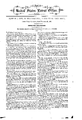
- Figure 1 is a view of the velocipede in perspective.
- Figure 2 is a sectional view.
- Fignre is an enlarged sectional View of the hub and axle, and a portion of the swinging support for seat.
- M is the tire.
- -A is a shield, a fractional portion only beingshown, for the purpose of protecting the rider from the revolv ⁇ ing spokes.
- This shield is made of wire-work, or other suitable material, and is bound by a rim, G, and at its centre there is an opening, allowing it to go over the shoulder ofthe hub, and fit close to the spokes. It is fastened to the wheel by screws, at c', and is, therefore,'detach able. f
- R is the crank, attached to the 'end of the axle X, fig. 2, squared (see iig. 3, a) for its reception, and is held rrnly in its position by the screw T.
- the support for seat N swings upon the axle X, fig. 2, by means of an eye, or opening, O, fig. 3, encompassing the axle, and allowing it to revolve through it.A It rests upon shoulders or boxing only, y, iig. 3, the interior, o, iig. 3, being hollowed out, in order to have as little friction as possible.
- Z is a continuation of swing N, and is provided with a slide, z, fig. 2, playing into swing N, and held in position by the bolt or screw S.
- the seat D can be detached at Z, the use of side-saddle or other seat.
- the arms E in one end of which are the bearings for the treadle H, are attached at F to square projections on swing N, and are reversible, allowing a person to have either arm within the interior of the whee upon moving oif.
- the pitman P is attached to the treadle H at h', connecting, by a pin'or pivot, at other end, with crank R.
- the pitman P can be detached at h', and be attached to handle B U at b, thus enabling the rider to use the hand as a motor, instead of the foot.
- the handle B U has its bearings in thearm Q','which arm is attached at its other end to the swing N,upon, a squared projection, .and is also reversible.
- FIG. 2 shows the relative position of the seat D to' the plane ofthe til'e and axis of motion, and also more plainly the manner in which the support Z plays or slides into the swing N at z', for purpose of adjusting centre of gravity for persons of diierent weights.
- Fig. 3 shows the hub W, with the axle X, of one piece, or rigid, the axle squared at x', for the reception or' the crank, which is held in position by bolt or 'screw T. l
- rlhe swing N is to have suflciently wide shoulders y, to prevent its swinging outwardly against the revolving-spokes.
- lhe velocipede is to'be made of malleableizedvcastiron, steel, or other suitable material, to enable the spokes to resist the indirect pressure or weight of the rider; and the support (swing) for seat, also of strong rigid material, 'rn order to not give, and thereby e11- danger the rider by interference from the revolvingspokes.
Landscapes
- Health & Medical Sciences (AREA)
- General Health & Medical Sciences (AREA)
- Physical Education & Sports Medicine (AREA)
- Motorcycle And Bicycle Frame (AREA)
Description
1. J. on.
Velocipde.
No. 87,285. Patenied Feb. 23, 1889.
' @anni i @te JOSEPH J. OTT, OF WASHINGTON, DISTRICT OF COLUMBIA.
Letters Patent No. 87,285, dated February 23, 1869.
IMPROVE!) A'VIEI1'1.|OCIPIE!IDE.
The Schedule referred to in these Letters Patent and making part of the same.
To all whom it may concern:
Be it known that I, J osEPH J. OTT, Aof the city of Vashi'ngton, in the District of Columbia, have invented a new and improved Form of Velocipede, and I do hereby declare that the following is a full and exact description thereof, reference being had to the accompanying drawings, and letters of reference marked thereon.
The nature of my invention consists in constructing a velocipede of only one wheel.
This wheel is so formed, by means of curved spokes, as to have the hub and axle, with attachments for movement, sufficiently out of the plane of the tire to permit the rider, by means of a seat swingingupon the axle, to sit in the plane of the tire, and always to bring the centre of gravity .belowthe axis of motion, and the line of directi on,(referrin g to gravity,) at pleasure, either within the plane of the tire, for forward movement, or, by an inclination of the body, without the said plane, to either right lor left, for a corresponding change in direc` tion.
As in the two-wheeled (both in same plane) velocipede, the upright position of the wheel is maintained by the centrifugal force generated by the motive-power;
but unlike that velocipede',change of direction is effected by a simple inclination of the body, which, changing the centre of gravity, brings into play a centripetal force, which causes the velocipede to swing around into another direction.
By the use of a single wheel, there are gained a nnmber of advantages over the two-wheeled velocipede.
First, lless friction, there being only one axle, and theponly friction onthat being `with the boxing of the swinging support for seat.
Second, dispensing with :a second or guide-wheel, there is also dispensed with the necessary appliances for supports of axles, the long support for seat, the guiding-levers, and the expense and weight of a second wheel. v
Third, guiding by an inclination of the body, there will be less fatigue to the rider; it often being necessary toA exert a great deal of strength to maintain in position, or govern, the 'guide-wheel.
Fourth, there can be used a much larger wheel with-` out correspondingly endangering the safety ofthe rider, on account of height of seat, and, therefore, greater speed can be attained with less fatigue to the rider; for,.with levers ofthe same length, in this case it will be somewhat harder to overcome the inertia, but afterwards the difference in exerted strength will be hardly appreciable, besides requiring less rapid movements of the hand or feet.
Fifth, being entirely open on one side, it offers greater advantages yfor ladies use. They canv assume, by sidesaddle, the same position as on horseback, using thev Iright arm asa motor, the left being outward and free. To enable others skilled in the art to make'and use the same, I will proceed to describe its construction and operation, referring to the annexed drawings,which forma part of this specification.
Figure 1 is a view of the velocipede in perspective.
Figure 2 is a sectional view.
Fignre is an enlarged sectional View of the hub and axle, and a portion of the swinging support for seat.
In g. l, M is the tire.
hub W, fig. 2.
-A is a shield, a fractional portion only beingshown, for the purpose of protecting the rider from the revolv` ing spokes. l
This shield is made of wire-work, or other suitable material, and is bound by a rim, G, and at its centre there is an opening, allowing it to go over the shoulder ofthe hub, and fit close to the spokes. It is fastened to the wheel by screws, at c', and is, therefore,'detach able. f
R is the crank, attached to the 'end of the axle X, fig. 2, squared (see iig. 3, a) for its reception, and is held rrnly in its position by the screw T.
Between the crank R and the hub W, fig. 2, the support for seat N swings upon the axle X, fig. 2, by means of an eye, or opening, O, fig. 3, encompassing the axle, and allowing it to revolve through it.A It rests upon shoulders or boxing only, y, iig. 3, the interior, o, iig. 3, being hollowed out, in order to have as little friction as possible.
Z is a continuation of swing N, and is provided with a slide, z, fig. 2, playing into swing N, and held in position by the bolt or screw S.
It is provided with this slide, to enable persons of diiferent weights, as may be necessary, to` bring the seat nearer the plane of tire, or further without it, as for persons of very light weight. v
Through the support Z plays the direct support for seat, or upright L, having its lower end threaded, in order to raise or lower seat.
The seat D can be detached at Z, the use of side-saddle or other seat.
The arms E, in one end of which are the bearings for the treadle H, are attached at F to square projections on swing N, and are reversible, allowing a person to have either arm within the interior of the whee upon moving oif.
The pitman P is attached to the treadle H at h', connecting, by a pin'or pivot, at other end, with crank R. The pitman P can be detached at h', and be attached to handle B U at b, thus enabling the rider to use the hand as a motor, instead of the foot.
The handle B U has its bearings in thearm Q','which arm is attached at its other end to the swing N,upon, a squared projection, .and is also reversible.
The wheel Klis attached to thetreadle H at outer end, and revolves with it, thus acting as a brake when pressed againstb'y the foot directly, or-by a rubber acted, upon by the foot.
in order to allow m', the spokes, curving outward, and meeting in the Fig. 2 shows the relative position of the seat D to' the plane ofthe til'e and axis of motion, and also more plainly the manner in which the support Z plays or slides into the swing N at z', for purpose of adjusting centre of gravity for persons of diierent weights.
Fig. 3 shows the hub W, with the axle X, of one piece, or rigid, the axle squared at x', for the reception or' the crank, which is held in position by bolt or 'screw T. l
In this fig. 3 is also more plainly shown the manner in which N, the swing, or support for seat, is attached to the Wheel, by the eye O encompassing the axle, between the crank at a. and the hub W', simply hanging from and swinging upon the axle X, as the crank turns the axle within it, and along with its axle the Wheel.
rlhe swing N is to have suflciently wide shoulders y, to prevent its swinging outwardly against the revolving-spokes.
lhe velocipede is to'be made of malleableizedvcastiron, steel, or other suitable material, to enable the spokes to resist the indirect pressure or weight of the rider; and the support (swing) for seat, also of strong rigid material, 'rn order to not give, and thereby e11- danger the rider by interference from the revolvingspokes.
Having thus fully described my invention,
What I claim as new, and desire to secure by Letters Patent, is as follows:
1. I claim the velocipede, consisting of one wheel, with outwardly-curved spokes, having the hub, axle,
and motive-power apparatus ont of the plane of the tire ot' the wheel, and the seat swinging on the axle, substantially as described.
2. In combination with the wheel, I claim the additional rim C, having the Wire screen .A` attached thereto, as described.
3. l claim the swinging arm, or support for seat N, and the manner cf attaching it to the velocipede, by means of an eye or opening, O, fig. 3, having the interior hollowed out, resting and swinging, by its boxing, i
upon the revolving axle, between the crank and hub, as described. e
4. I claim the arm Z, playing into main arm N, by a slide, and held in position by a screw or pin, S, and for the purposes described.
5. I claim the manner of attaching the arms E E and Q, in which the handle and treadle have their bearings, to the swing N, upon square projections, by means of which said arins are adjustable and reversible, as described. I
6.1 claim the wheel or brake K, attached to end of treadle H,'and revolving with, as described, and for the purposes set forth.
In testimony that I claim the foregoing, I have hereunto set my hand and seal, this 9th day of February,
JOSEPH J O'lT. [11.5.] Witnesses:
M. GARDNER, W. H. FULLER.
Publications (1)
| Publication Number | Publication Date |
|---|---|
| US87285A true US87285A (en) | 1869-02-23 |
Family
ID=2156770
Family Applications (1)
| Application Number | Title | Priority Date | Filing Date |
|---|---|---|---|
| US87285D Expired - Lifetime US87285A (en) | Improved velocipede |
Country Status (1)
| Country | Link |
|---|---|
| US (1) | US87285A (en) |
Cited By (1)
| Publication number | Priority date | Publication date | Assignee | Title |
|---|---|---|---|---|
| US4244567A (en) * | 1979-12-10 | 1981-01-13 | George H. Linzee | Space tumbler |
-
0
- US US87285D patent/US87285A/en not_active Expired - Lifetime
Cited By (1)
| Publication number | Priority date | Publication date | Assignee | Title |
|---|---|---|---|---|
| US4244567A (en) * | 1979-12-10 | 1981-01-13 | George H. Linzee | Space tumbler |
Similar Documents
| Publication | Publication Date | Title |
|---|---|---|
| US87285A (en) | Improved velocipede | |
| US86235A (en) | Improvement in velocipedes | |
| US88683A (en) | Improved velocipede | |
| US89695A (en) | Improvement in velocipede | |
| US96208A (en) | Improved velocipede | |
| US441409A (en) | Velocipede | |
| US92044A (en) | Improvement in velocipedes | |
| US88930A (en) | Improved velocipede | |
| US90700A (en) | Luke w | |
| US328353A (en) | Bicycle | |
| US88889A (en) | Improvement in velocipede | |
| US91169A (en) | Friedeich schmitt | |
| US84163A (en) | Peters | |
| US87205A (en) | Improved velocipede | |
| US90470A (en) | Improved velocipede | |
| US228996A (en) | Velocipede | |
| US77167A (en) | Improved mechanical powee | |
| US88759A (en) | James w | |
| US88120A (en) | Improved velocipede | |
| US91896A (en) | Improvement in velocipede | |
| US93433A (en) | Improvement in velocipedes | |
| US92574A (en) | Improved method of propelling- sleds | |
| US360392A (en) | pkindle am | |
| US91510A (en) | Improvement in velocipedes | |
| US342620A (en) | Velocipede |