US8718873B2 - Electric power steering device - Google Patents
Electric power steering device Download PDFInfo
- Publication number
- US8718873B2 US8718873B2 US12/672,328 US67232808A US8718873B2 US 8718873 B2 US8718873 B2 US 8718873B2 US 67232808 A US67232808 A US 67232808A US 8718873 B2 US8718873 B2 US 8718873B2
- Authority
- US
- United States
- Prior art keywords
- steering
- vehicle speed
- torque
- assist force
- calculated
- Prior art date
- Legal status (The legal status is an assumption and is not a legal conclusion. Google has not performed a legal analysis and makes no representation as to the accuracy of the status listed.)
- Expired - Fee Related, expires
Links
Images


Classifications
-
- B—PERFORMING OPERATIONS; TRANSPORTING
- B62—LAND VEHICLES FOR TRAVELLING OTHERWISE THAN ON RAILS
- B62D—MOTOR VEHICLES; TRAILERS
- B62D5/00—Power-assisted or power-driven steering
- B62D5/04—Power-assisted or power-driven steering electrical, e.g. using an electric servo-motor connected to, or forming part of, the steering gear
- B62D5/0457—Power-assisted or power-driven steering electrical, e.g. using an electric servo-motor connected to, or forming part of, the steering gear characterised by control features of the drive means as such
- B62D5/046—Controlling the motor
- B62D5/0463—Controlling the motor calculating assisting torque from the motor based on driver input
-
- B—PERFORMING OPERATIONS; TRANSPORTING
- B62—LAND VEHICLES FOR TRAVELLING OTHERWISE THAN ON RAILS
- B62D—MOTOR VEHICLES; TRAILERS
- B62D6/00—Arrangements for automatically controlling steering depending on driving conditions sensed and responded to, e.g. control circuits
- B62D6/008—Control of feed-back to the steering input member, e.g. simulating road feel in steer-by-wire applications
Definitions
- the present invention relates to a power steering device for a vehicle such as an automobile and, more particularly, to an electric power steering device.
- a steering device of steer-by-wire-type which controls steering reactive force in accordance with steering torque.
- the steering device suppresses lowering of steering reactive force in a specific steering frequency area by reducing a gain of a transfer function from steering angle to steering torque.
- an electric power steering device which conducts damping control (viscosity compensation control) on the basis of steering angular velocity.
- the electric power steering device enhances the component of around yaw rate resonance frequency contained in steering angular velocity signal to thereby suppress lowering of steering reactive force when steering frequency is at or near yaw rate resonance frequency.
- magnitude of steering reactive force lowers at a specific steering frequency and the phase of steering reactive force varies in accordance with steering frequency.
- the phase of steering reactive force advances, so that damping property increases and viscous feeling sensed by a driver rises.
- phase of steering reactive force delays, so that damping property decreases and viscous feeling sensed by a driver lowers.
- a primary object of the present invention is to reduce the variation of viscous feeling due to the change of steering velocity by compensating the lowering in magnitude of steering reactive force response against steering angle at a specific steering velocity and by suppressing the variation in phase of steering reactive force due to the change of steering velocity, and to provide an electric power steering apparatus which presents better steering feeling than conventional steering devices.
- the present invention provides an electric power steering device having a steering input means which is operated by a driver, a steering means which is provided between the steering input means and steered wheels and steers the steered wheels in response to steering operation conducted by a driver with the steering input means, an electric steering assist force generating means for imparting steering assist force to the steering means, a steering force attaining means for attaining steering force imparted to the steering input means by a driver, and a control means for calculating a target steering assist force in accordance with at least the steering force and controlling steering assist force generated by the steering assist force generating means on the basis of the target steering assist force, wherein the electric power steering device has a steering velocity attaining means for attaining velocity of steering operation conducted with the steering input means as steering velocity, and the control means calculates a correction amount by filtering the steering velocity with a filter of second-order lag and first-order advance; corrects the target steering assist force with the correction amount; and controls the steering assist force generated by the steering assist force generating means on the basis of the corrected target steering
- the present invention also provides an electric power steering device having a steering input means which is operated by a driver, a steering means which is provided between the steering input means and steered wheels and steers the steered wheels in response to steering operation conducted by a driver with the steering input means, an electric steering assist force generating means for imparting steering assist force to the steering means, a steering force attaining means for attaining steering force imparted to the steering input means by a driver, and a control means for calculating a target steering assist force in accordance with at least the steering force and controlling steering assist force generated by the steering assist force generating means on the basis of the target steering assist force, wherein the electric power steering device has a steering velocity attaining means for attaining velocity of steering operation conducted with the steering input means as steering velocity; the control means calculates a correction amount on the basis of steering velocity; corrects the target steering assist force with the correction amount; and controls the steering assist force generated by the steering assist force generating means on the basis of the corrected target steering assist force; and the control means calculates the correction amount so that when
- the mass and yaw inertia moment of a vehicle 100 are denoted by M and I z , respectively, and cornering forces of a front wheel 102 f which is a steered wheel and rear wheel 102 r which is a non-steered wheel are denoted by F f and F r , respectively.
- the distances between a gravity center 104 of the vehicle and between front wheel axle 106 f and rear wheel axle 106 r are denoted by L f and L r , respectively; slip angle of the vehicle is denoted by ⁇ ; and yaw rate of the vehicle is denoted by ⁇ .
- Gravity acceleration is denoted by g and normalized inertia moment about vertical axis of the vehicle is denoted by I zN .
- the distance L f between a gravity center 104 of the vehicle and front wheel axle 106 f the distance L r between a gravity center 104 of the vehicle and rear wheel axle 106 r , the cornering powers K f and K r , respectively, of the front wheel 102 f and the rear wheel 102 r , and yaw inertia moment I z of the vehicle are given by the following associated equations 6 to 10:
- L f L ⁇ ( 1 - D wf ) ( 6 )
- L r LD wf ( 7 )
- K f C f ⁇ M ⁇ ⁇ D wf ⁇ g ( 8 )
- K r C r ⁇ M ⁇ ( 1 - D wf ) ⁇ g ( 9 )
- T q ⁇ ⁇ ( VL ⁇ s 2 + C r ⁇ gL ⁇ s + C r ⁇ gV ) ⁇ VgMD wf ⁇ C f V 2 ⁇ L ⁇ s 2 + ( C f + C r ) ⁇ gVL ⁇ s + ( C r - C f ) ⁇ gV 2 + C f ⁇ C r ⁇ g 2 ⁇ L ⁇ ⁇ ( 12 )
- a correction torque for steering reactive torque T q is now denoted by T cmp and the correction torque T cmp is deemed to satisfy the under-described equation 14.
- the correction of steering reactive torque T q with the correction torque T cmp by imparting the correction torque T cmp to the front wheel 102 f about king pin axis makes it possible to prevent the magnitude of the steering reactive torque transmitted to the steering wheel serving as a steering input means from varying due to the change of steering velocity and makes it as well possible to prevent the phase of the steering reactive torque from varying due to the change of steering velocity.
- the correction makes it possible to keep constant the dynamic response property of steering reactive torque of a vehicle against steering velocity.
- G s G N s 2 ( 22 )
- the correction torque T cmps is a value obtained by multiplying steering velocity s ⁇ achieved by a driver with a transfer function of second-order lag and first-order advance so that although neither the steered angel ⁇ of the front wheel nor steering angle ⁇ is known, the correction torque T cmps can be calculated if steering velocity is known.
- the above-described transfer function can be considered as a product of a filter of second-order lag and first-order advance and a gain G s .
- a correction amount is calculated by filtering steering velocity with a filter of second-order lag and first-order advance; modifying target steering assist force with the correction amount to calculate a final target steering assist force; and controlling the steering assist force generated by the steering assist force generating means in accordance with the final target steering assist force.
- a correction amount is calculated on the basis of steering velocity; modifying the target steering assist force with the correction amount to calculate a final target steering assist force; and controlling the steering assist force generated by the steering assist force generating means on the basis of the final target steering assist force.
- the correction amount is calculated so that when magnitude of steering velocity is in a specific area, the magnitude of the correction amount is smaller than that when steering velocity is in an area other than the specific area, and when steering velocity is in an area higher than the specific area, the phase of steering reactive force relative to steering operation is shifted toward delay side than that when steering velocity is in an area lower than the specific area.
- the above-mentioned latter configuration may be such that: the control means calculates the correction amount so that when magnitude of steering velocity is in a specific area, the magnitude of the correction amount is smaller than that when steering velocity is in an area other than the specific area; when steering velocity is in an area higher than the specific area, the phase of steering reactive force relative to steering operation is shifted toward delay side; and when steering velocity is in an area lower than the specific area, the phase of steering reactive force relative to steering operation is shifted toward advance side.
- vehicle mass M of a two-wheel model is denoted as 1800 kg; normalized inertia moment I zN is denoted as 1; allocation rate D wf of vehicle load for front wheel is denoted as 0.55; wheel base is denoted as 2.7 m; normalized cornering powers C f and C r of the front and rear wheels are denoted 10 and 20, respectively; damping ratio ⁇ is denoted as 0.05 m; and steering gear ratio N s is denoted as 18.
- this two-wheel model is called as “an illustrative two-wheel model”.
- time constant T n of first-order advance of the filter in the above-described equation 23 is a value expressed by the above-described equation 18, even if the time constant T n is zero, it is possible to prevent, not perfectly but positively, the magnitude and the phase of the steering reactive torque from varying due to the change of steering velocity.
- the above-mentioned configuration may be such that: the time constant of first-order advance of the filter is zero.
- the time constant of first-order advance of the filter is zero and the filter is a filter of second-order lag.
- the effect is lower than that in the case where the time constant of first-order advance is calculated according to the above-described equation 18, the variation of steering reactive torque in magnitude and phase can positively be suppressed and necessary calculation amount involved can be reduced.
- the filter parameters represented by these equations are functions of vehicle speed V.
- the filter parameters are also functions of normalized cornering powers C f and C r of the front and rear wheels, respectively, and normalized cornering powers C f and C r varies in accordance with vehicle weight and friction coefficient of road surface.
- the above-mentioned configuration may be such that: the parameters of the filter are variably set in accordance with at least any one of vehicle speed, vehicle weight and friction coefficient of road surface.
- the parameters of the filter are variably set in accordance with at least any one of vehicle speed, vehicle weight and friction coefficient of road surface. Accordingly, as compared with the case where the parameters of the filter are constant, the filter can be more appropriately set in accordance with vehicle speed, vehicle weight and friction coefficient of road surface and it is thus possible to more properly reduce the variation of steering reactive torque in magnitude and phase due to the change of steering velocity, regardless of vehicle speed, vehicle weight and friction coefficient of road surface.
- the gain G s expressed by the equation is a function of vehicle speed V, vehicle weight and friction coefficient of road surface.
- FIG. 16 shows the relationship between vehicle speed V and the gain G s with respect to the illustrative two-wheel model. As shown in FIG. 16 , the gain G s is negative when vehicle speed V is in an area lower than approximately 60 km/h but is positive and gradually increases as vehicle speed V goes up when vehicle speed V is in an area higher than approximately 60 km/h. In this connection, it is assumed that the sign inversion of the gain G s occurs due to the fact that, as shown in FIG. 17 , the time constant T n becomes infinite when vehicle speed V is approximately 60 km/h and the sign of the gain G s inverts across the vehicle speed V of around 60 km/h.
- the above-mentioned configuration may be such that: when vehicle speed is low, the control means reduces the magnitude of the correction amount, as compared with the case where vehicle speed is high.
- the gain G s is negative when vehicle speed V is in a lower area. However, even if the gain G s is set to zero when vehicle speed V is in a lower area, it is possible to positively reduce the variation of steering reactive torque in magnitude and phase due to the change of steering velocity in medium and higher vehicle speed area where the gain G s is not set to zero.
- the above-mentioned configuration may be such that: the control means sets the correction amount to zero when vehicle speed is not higher than a reference vehicle speed.
- the correction amount is set to zero when vehicle speed is not higher than a reference vehicle speed. Accordingly, the control of steering assist torque can easily be executed when vehicle speed is not more than a reference vehicle speed and it is possible to positively reduce the variation of steering reactive torque in magnitude and phase due to the change of steering velocity when vehicle speed is higher than a reference vehicle speed.
- the above-mentioned configurations may be such that: the steering input means is a steering wheel and the control means calculates a target assist torque on the basis of at least steering torque; calculates a correction torque by filtering steering velocity with a filter of second-order lag and first-order advance; corrects target steering assist torque with the correction torque; and controls the steering assist force generated by the steering assist force generating means on the basis of the corrected target steering assist torque.
- control means calculates the correction torque T cmps according to the above-described equation 23.
- T cmps ⁇ 2 ⁇ ( G s + G s ⁇ T n ⁇ s ) ( s 2 + 2 ⁇ ⁇ ⁇ ⁇ s + ⁇ 2 ) ⁇ s ⁇ ⁇ ( 24 )
- control means calculates the correction torque T cmps according to the above-described equation 24.
- control means calculates the time constant G s ⁇ T n according to the above-described equation 18.
- control means calculates the correction torque T cmps according to the under-described equation 25 in which the time constant T n in the above-described equation 23 is set to zero.
- T cmps ⁇ 2 ( s 2 + 2 ⁇ ⁇ ⁇ ⁇ s + ⁇ 2 ) ⁇ G s ⁇ s ⁇ ⁇ ( 25 )
- control means calculates the filter parameters according to the above-described equations 19 to 21.
- control means calculates the gain G s according to the above-described equations 17 and 22.
- G s is a value less than that calculated according to the above-described equations 17 and 22, it is possible to more positively reduce the variation of steering reactive torque in magnitude and phase due to the change of steering velocity than in the case where the target steering assist torque is not corrected with the correction torque.
- the solid lines in FIGS. 19 and 20 show the relationships between steering frequency f (Hz) and steering reactive torque T q (Nm) and between steering frequency f (Hz) and phase ⁇ (deg) of steering reactive torque, respectively, for vehicle speed V of 100 km/h, with respect to the case where the magnitude of the gain G s is set to 50% of that calculated according to the above-described equations 17 and 22 in the illustrative two-wheel model. It is understood from the comparison of solid lines and broken lines (showing values when no correction is made with the correction amount) in FIGS. 19 and 20 that even in the case where the magnitude of the gain G s is set to 50% of innate value, it is still possible to positively reduce the variation of steering reactive torque in magnitude and phase due to the change of steering velocity.
- FIGS. 21 and 22 show the relationships between steering frequency f (Hz) and steering reactive torque T q (Nm) and between steering frequency f (Hz) and phase ⁇ (deg) of steering reactive torque, respectively, for vehicle speed V of 140 km/h, with respect to the case where the gain G s is calculated based on the vehicle speed V of 140 km/h and the correction torque T cmps is calculated according to the above-described equation 23 utilizing the time constant T n and the filter parameters calculated in advance for vehicle speed V of 100 km/h and the gain G s in the illustrative two-wheel model.
- FIGS. 23 and 24 show the relationships between steering frequency f (Hz) and steering reactive torque T q (Nm) and between steering frequency f (Hz) and phase ⁇ (deg) of steering reactive torque, respectively, for vehicle speed V of 180 km/h, with respect to the case where the gain G s is calculated based on the vehicle speed V of 80 km/h and the correction torque T cmps is calculated according to the above-described equation 23 utilizing the time constant T n and the filter parameters calculated in advance for vehicle speed V of 100 km/h and the gain G s in the illustrative two-wheel model.
- control means calculates the gain G s on the basis of vehicle speed V and calculates the correction torque T cmps according to the above-described equation 23 utilizing the time constant T n and the filter parameters calculated in advance for a specific vehicle speed V and the gain G s .
- control means calculates the product G s ⁇ T n of the time constant T n and the gain G s on the basis of vehicle speed V according to the under-described equation 26 and calculates the correction torque T cmps according to the above-described equation 24 utilizing the filter parameters calculated in advance for a specific vehicle speed V and the product G s ⁇ T n .
- FIGS. 25 and 26 show the relationships between steering frequency f (Hz) and steering reactive torque T q (Nm) and between steering frequency f (Hz) and phase ⁇ (deg) of steering reactive torque, respectively, for vehicle speed V of 140 km/h, with respect to the case where the gain G s is calculated based on the vehicle speed V of 140 km/h and the correction torque T cmps is calculated according to the above-described equation 25 utilizing the filter parameters calculated in advance for vehicle speed V of 100 km/h and the gain G s in the illustrative two-wheel model.
- the control means calculates the gain G s on the basis of vehicle speed V and calculates the correction torque T cmps according to the above-described equation 25 utilizing the filter parameters calculated in advance for a specific vehicle speed V and the gain G s .
- the relationship between vehicle speed V and the gain G s is as shown in FIG. 16 .
- the relationship between vehicle speed V and the gain G s can be approximated to the relationship shown in FIG. 27 .
- control means calculates the gain G s based on vehicle speed V according to a map corresponding to the graph shown in FIG. 27 .
- the relationship between vehicle speed V and the time constant T n is as shown in FIG. 17 .
- the relationship between vehicle speed V and the gain G s is approximated to the relationship shown in FIG. 27 , the sign of the gain G s does not reverse due to the change of vehicle speed V. Accordingly, the relationship between vehicle speed V and the time constant T n can be approximated to the relationship shown in FIG. 28 .
- control means calculates the time constant T n based on vehicle speed V according to a map corresponding to the graph shown in FIG. 28 .
- the relationship between vehicle speed V and the product G s ⁇ T n is as shown in FIG. 18 .
- the relationship between vehicle speed V and the product G s ⁇ T n can be approximated to the relationship shown in FIG. 29 .
- control means calculates the product G s ⁇ T n based on vehicle speed V according to a map corresponding to the graph shown in FIG. 29 .
- FIG. 1 is a diagrammatical view of a first embodiment of an electric power steering device according to the present invention.
- FIG. 2 is a flowchart showing an assist torque control routine in a first embodiment.
- FIG. 3 is a flowchart showing an assist torque control routine in a second embodiment.
- FIG. 4 is a flowchart showing an assist torque control routine in a third embodiment.
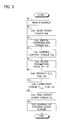
- FIG. 5 is a flowchart showing an assist torque control routine in a fourth embodiment.
- FIG. 6 is a flowchart showing an assist torque control routine in a fifth embodiment.
- FIG. 7 is a flowchart showing an assist torque control routine in a sixth embodiment.
- FIG. 8 is a flowchart showing an assist torque control routine in a seventh embodiment.
- FIG. 9 is a flowchart showing an assist torque control routine in a eighth embodiment.
- FIG. 10 is a flowchart showing an assist torque control routine in a ninth embodiment.
- FIG. 11 is an explanatory view showing a two-wheel model of a vehicle pedal in counter-clockwise turning state.
- FIG. 12 is a graph showing the relationship between steering frequency f (Hz) and steering reactive torque T q (Nm) for vehicle speed of 100 km/h, with respect to the case where a target steering assist torque is not corrected with a correction torque (broken line) and the case where a target steering assist torque is corrected with a correction torque (solid line).
- FIG. 13 is a graph showing the relationship between steering frequency f (Hz) and phase ⁇ (deg) of steering reactive torque for vehicle speed of 100 km/h, with respect to the case where a target steering assist torque is not corrected with a correction torque (broken line) and the case where a target steering assist torque is corrected with a correction torque (solid line).
- FIG. 14 is a graph showing, similar to FIG. 12 , the relationship between steering frequency f (Hz) and steering reactive torque T q (Nm) with respect to the case where time constant of a filter of first-order advance is zero and vehicle speed is 100 km/h.
- FIG. 15 is a graph showing, similar to FIG. 13 , the relationship between steering frequency f (Hz) and phase ⁇ (deg) of steering reactive torque with respect to the case where time constant of a filter of first-order advance is zero and vehicle speed is 100 km/h.
- FIG. 16 is a graph showing the relationship between vehicle speed V and a gain G s with respect to the illustrative two-wheel model of a vehicle.
- FIG. 17 is a graph showing the relationship between vehicle speed V and a time constant T n with respect to the illustrative two-wheel model of a vehicle.
- FIG. 18 is a graph showing the relationship between vehicle speed V and a product G s ⁇ T n with respect to the illustrative two-wheel model of a vehicle.
- FIG. 19 is a graph showing, similar to FIG. 12 , the relationship between steering frequency f (Hz) and steering reactive torque T q (Nm) for vehicle speed of 100 km/h, with respect to the case where magnitude of a gain G s is set to 50% in the illustrative two-wheel model of a vehicle.
- FIG. 20 is a graph showing, similar to FIG. 13 , the relationship between steering frequency f (Hz) and phase ⁇ (deg) of steering reactive torque for vehicle speed of 100 km/h, with respect to the case where magnitude of a gain G s is set to 50% in the illustrative two-wheel model of a vehicle.
- FIG. 21 is a graph showing, similar to FIG. 12 , the relationship between steering frequency f (Hz) and steering reactive torque T q (Nm) for vehicle speed of 140 km/h, with respect to the case where a gain G s is calculated based on vehicle speed V of 140 km/h and a correction torque T cmps is calculated utilizing a time constant T n and filter parameters calculated in advance for vehicle speed V of 100 km/h and a gain G s in the illustrative two-wheel model of a vehicle.
- FIG. 22 is a graph showing, similar to FIG. 13 , the relationship between steering frequency f (Hz) and phase ⁇ (deg) of steering reactive torque for vehicle speed of 140 km/h, with respect to the case where a gain G s is calculated based on vehicle speed V of 140 km/h and a correction torque T cmps is calculated utilizing a time constant T n and filter parameters calculated in advance for vehicle speed V of 100 km/h and a gain G s in the illustrative two-wheel model of a vehicle.
- FIG. 23 is a graph showing, similar to FIG. 12 , the relationship between steering frequency f (Hz) and steering reactive torque T q (Nm) for vehicle speed of 80 km/h, with respect to the case where a gain G s is calculated based on vehicle speed V of 80 km/h and a correction torque T cmps is calculated utilizing a time constant T n and filter parameters calculated in advance for vehicle speed V of 100 km/h and a gain G s in the illustrative two-wheel model of a vehicle.
- FIG. 24 is a graph showing, similar to FIG. 13 , the relationship between steering frequency f (Hz) and phase ⁇ (deg) of steering reactive torque for vehicle speed of 80 km/h, with respect to the case where a gain G s is calculated based on vehicle speed V of 80 km/h and a correction torque T cmps is calculated utilizing a time constant T n and filter parameters calculated in advance for vehicle speed V of 100 km/h and a gain G s in the illustrative two-wheel model of a vehicle.
- FIG. 25 is a graph showing, similar to FIG. 12 , the relationship between steering frequency f (Hz) and steering reactive torque T q (Nm) for vehicle speed of 140 km/h, with respect to the case where a gain G s is calculated based on vehicle speed V of 140 km/h and a correction torque T cmps is calculated utilizing a time constant T n and filter parameters calculated in advance for vehicle speed V of 100 km/h and a gain G s in the illustrative two-wheel model of a vehicle.
- FIG. 26 is a graph showing, similar to FIG. 13 , the relationship between steering frequency f (Hz) and phase ⁇ (deg) of steering reactive torque for vehicle speed of 140 km/h, with respect to the case where a gain G s is calculated based on vehicle speed V of 140 km/h and a correction torque T cmps is calculated utilizing a time constant T n and filter parameters calculated in advance for vehicle speed V of 100 km/h and a gain G s in the illustrative two-wheel model of a vehicle.
- FIG. 27 is a graph showing the relationship between vehicle speed V and a gain G s for calculating a gain G s .
- FIG. 28 is a graph showing the relationship between vehicle speed V and a time constant T n for calculating a time constant T n .
- FIG. 29 is a graph showing the relationship between vehicle speed V and a product G s ⁇ T n for calculating a product G s ⁇ T n .
- FIG. 30 is a graph showing the relationship between vehicle speed V and time cycle ⁇ of natural oscillation.
- FIG. 31 is a graph showing the relationship between vehicle speed V and damping ratio ⁇ .
- FIG. 32 is a graph showing the relationship among vehicle speed V, a gain G s and friction coefficient ⁇ of road surface.
- FIG. 33 is a graph showing the relationship among vehicle speed V, a gain G s and vehicle weight W.
- FIG. 34 is a graph showing the relationship among vehicle speed V, a gain G s and allocation rate D wf of vehicle load for front wheel.
- FIG. 35 is a graph showing the relationship among vehicle speed V, time cycle ⁇ of natural oscillation and friction coefficient ⁇ of road surface.
- FIG. 36 is a graph showing the relationship among vehicle speed V, damping ratio ⁇ and friction coefficient ⁇ of road surface.
- FIG. 37 is a graph showing the relationship among vehicle speed V, a product G s ⁇ T n and friction coefficient ⁇ of road surface.
- FIG. 1 is a diagrammatical view of a first embodiment of an electric power steering device according to the present invention.
- reference numeral 10 wholly denotes an electric power steering device according to the present invention.
- Reference numerals 12 FL and 12 FR denote left and right front wheels, respectively, which are steered wheels of a vehicle 14
- reference numerals 12 RL and 12 RR denote left and right rear wheels, respectively, which are non-steered wheels of the vehicle 14 .
- the electric power steering device 10 has a steering wheel 16 serving as a steering input means which is operated by a driver, a steering apparatus 18 , a power steering actuator 20 , and an electronic control unit 22 .
- the steering apparatus 18 is provided between the steering wheel 16 and the left and right front wheels 12 FL and 12 FR and steers the left and right front wheels 12 FL and 12 FR in response to the steering operation of the steering wheel 16 by a driver.
- the steering apparatus 18 comprises a steering shaft 24 and a rack-and-pinion-type steering unit 26 .
- the upper end of the steering shaft 24 is coupled with the steering wheel 16 via torsion bar, not shown in the figure, and the lower end of the steering shaft 24 is coupled with a pinion shaft 30 of the steering unit 26 via a universal joint 28 .
- Tie rods 36 L and 36 R are pivotally connected at their inner ends with the opposite ends of a rack bar 32 of the steering unit 26 via ball joints 34 L and 34 R, respectively.
- the outer ends of the tie rods 36 L and 36 R are pivotally connected with distal ends of knuckle arms, not shown in the figure, of the left and right front wheels 12 FL and 12 FR, respectively.
- Linear motion of the rack bar 32 in the lateral direction of the vehicle is transferred to rotational motions around king pin axes, not shown in the figure, of the left and right front wheels 12 FL and 12 FR by the tie rods 36 L and 36 R, so that the left and right front wheels 12 FL and 12 FR are steered.
- the power steering actuator 20 has an electric motor 38 and a velocity reducing gear mechanism 40 which transmits the rotational torque of the electric motor 38 to the steering shaft 24 .
- the power steering actuator 20 generates steering assist force to drivingly rotate the steering shaft 24 relative to a vehicle body, thereby generating steering assist torque for reducing the steering burden of a driver.
- the steering shaft 24 is provided with a steering angle sensor 42 for detecting steering angle ⁇ and a torque sensor 44 for detecting steering torque Ts.
- the vehicle 14 is provided with a vehicle speed sensor 46 for detecting vehicle speed V.
- the steering angle sensor 42 and the torque sensor 44 detect steering angle ⁇ and steering torque Ts, respectively with clockwise turning direction of the vehicle being positive.
- input to the electronic control unit 22 are a signal indicating a steering angle ⁇ detected by the steering angle sensor 42 , a signal indicating steering torque Ts detected by the torque sensor 44 , and a signal indicating vehicle speed V detected by the vehicle speed sensor 46 .
- the electronic control unit 22 incorporates a microcomputer which may be of an ordinary type including a CPU, a RAM, a ROM, input and output port means and a common bus interconnecting these elements.
- the electronic control unit 22 calculates, according to the flowchart shown in FIG. 2 , a basic assist torque Tab for reducing the steering burden of a driver on the basis of a steering torque Ts and vehicle speed V.
- the electronic control unit 22 also calculates an inertia compensation torque Ttd for reducing an inertial feeling (harsh feeling) of steering on the basis of steering torque Ts, a differential value Tsd thereof and vehicle speed V.
- the electronic control unit 22 further calculates a damping control torque Tdp for enhancing a convergence characteristic of the steering wheel 16 on the basis of steering angle velocity ⁇ d which is a differential value of steering angle ⁇ , vehicle speed V, and steering torque Ts.
- the electronic control unit 22 calculates, according to the flowchart shown in FIG. 2 , a correction torque T cmps and calculates a final target assist torque Ta by summing a basic assist torque Tab, an inertia compensation torque Ttd, a damping control torque Tdp and a correction torque T cmps .
- the electronic control unit 22 calculates a final target assist torque Ta by modifying with a correction torque T cmps a basic target assist torque which is a sum of a basic assist torque Tab, an inertia compensation torque Ttd and a damping control torque Tdp.
- the electronic control unit 22 controls the electric motor 38 of the power steering actuator 20 on the basis of the final target assist torque Ta so that steering assist torque generated by the power steering actuator 20 conforms to the final target assist torque Ta.
- a basic target assist torque may be calculated in any manner known in the art as long as it is calculated as an assist torque for reducing the steering burden of a driver on the basis of at least steering torque.
- a basic assist torque Tab, an inertia compensation torque Ttd and a damping control torque Tdp may be calculated in any manner known in the art.
- the routine for controlling an assist torque in the first embodiment will be described below by referring to the flowchart shown in FIG. 2 .
- the control according to the routine shown in FIG. 2 is started by a closure of an ignition switch not shown in the figure and cyclically repeated.
- step 10 the signals such as a signal indicating steering torque Ts detected by the torque sensor 44 are read in.
- step 20 a basic assist torque Tab is calculated on the basis of steering torque Ts and vehicle speed V in a manner known in the art so that the magnitude of the basic assist torque Tab increases as the magnitude of steering torque Ts becomes larger and the magnitude of the basic assist torque Tab lowers as vehicle speed V becomes higher.
- step 30 an inertia compensation torque Ttd is calculated on the basis of steering torque Ts, a differential value Tsd thereof and vehicle speed V in a manner known in the art.
- step 40 a damping control torque Tdp is calculated on the basis of steering angle velocity ⁇ d, vehicle speed V and steering torque Ts in a manner known in the art
- step 50 filter parameters such as a time constant T n are calculated on the basis of vehicle speed V according to the above-described equations 18 to 21 with normalized cornering powers C f and C r of the front and rear wheels, respectively, a mass M of the vehicle, allocation rate D wf of vehicle load for front wheel and the other parameter being deemed to be known constant values.
- step 60 a gain G s is calculated on the basis of vehicle speed V according to the above-described equations 17 to 22 with a normalized cornering power C r of the rear wheel being a known constant value.
- a steering velocity s ⁇ is calculated as a time-differential value of steering angle ⁇ and a correction torque T cmps is calculated according to above-described equation 23 on the basis of filter parameters calculated in step 50 and a gain G s calculated in step 60 .
- a final target assist torque Ta is calculated by summing a basic assist torque Tab, an inertia compensation torque Ttd, a damping control torque Tdp and a correction torque T cmps .
- step 140 a control signal corresponding to the final target assist torque Ta is output to the electric motor 38 , thereby executing control of a steering assist torque so that assist torque for reducing a steering torque which is needed for a driver conforms to the final target assist torque Ta.
- a basic assist torque Tab an inertia compensation torque Ttd and a damping control torque Tdp are calculated in steps 20 to 40 , respectively.
- filter parameters such as a time constant T n are calculated according to the above-described equations 18 to 21 and in step 60 , a gain G s is calculated according to the above-described equations 17 to 22.
- a correction torque T cmps is calculated according to the above-described equation 23; in step 130 , a final target assist torque Ta is calculated by summing a basic assist torque Tab, an inertia compensation torque Ttd, a damping control torque Tdp and a correction torque T cmps ; and in step 140 , a steering assist torque is controlled so that it conforms to the final target assist torque Ta.
- FIG. 3 is a flowchart showing an assist torque control routine in a second embodiment of an electric power steering device according to the present invention.
- steps similar to those appearing in FIG. 2 are denoted by like step numbers appearing in FIG. 2 , and this applies to the flowcharts of third to ninth embodiments to be described later.
- steps 10 to 40 are executed in the same manner as in the first embodiment and after step 40 has been completed, step 60 is executed in the same manner as in the first embodiment without step 50 being executed.
- filter parameters such as a time constant T n expressed by the above-described equations 18 to 21 are calculated for vehicle speed V of for example 100 km/h and are stored in ROM. Therefore, in step 100 , steering velocity s ⁇ is calculated as a time-differential value of steering angle ⁇ and a correction torque T cmps is calculated according to the above-described equation 23 on the basis of vehicle speed V, filter parameters stored in ROM and a gain G s calculated in step 60 . Further, steps 130 and 140 are executed in the same manner as in the first embodiment.
- a correction torque T cmps can be calculated as in the first embodiment with the exception that a step corresponding to step 50 in the first embodiment is not executed and filter parameters stored in ROM are utilized.
- FIG. 4 is a flowchart showing an assist torque control routine in a third embodiment of an electric power steering device according to the present invention.
- steps 10 to 40 and steps 100 to 140 are executed in the same manner as in the first embodiment and after step 40 has been completed, in step 70 , a gain G s is calculated on the basis of vehicle speed V according to a map corresponding to the graph shown in FIG. 16 without any step corresponding to step 50 in the first embodiment being executed.
- a correction torque T cmps can be calculated as in the first embodiment with the exception that a step corresponding to step 50 in the first embodiment is not executed; filter parameters stored in ROM are utilized; and a gain G s is calculated according to a map corresponding to the graph shown in FIG. 16 .
- a correction torque T cmps is calculated according to the above-described equation 23, it is calculated as a value which is obtained by filtering steering velocity s ⁇ by a filter of second-order lag and first-order advance. Accordingly, in addition to positively and effectively suppress the variation in magnitude of steering torque which a driver feels when steering velocity changes, it is possible to positively and effectively suppress the variation in phase of steering torque which a driver feels, to thereby reduce the variation of viscous feeling that can come along with the change of steering velocity so as to positively and effectively enhance steering feeling.
- FIG. 5 is a flowchart showing an assist torque control routine in a fourth embodiment of an electric power steering device according to the present invention.
- steps 10 to 50 and steps 130 and 140 are executed in the same manner as in the first embodiment and after step 50 has been completed, in step 80 , a product G s ⁇ T n is calculated according to the above-described equation 24.
- a steering velocity s ⁇ is calculated as, for example, a time-differential value of steering angle ⁇ and a correction torque T cmps is calculated according to the above-described equation 24 on the basis of vehicle speed V, the filter parameters calculated in step 50 and the product G s ⁇ T n calculated in step 80 .
- a correction torque T cmps can be calculated as in the first embodiment with the exception that in step 80 a product G s ⁇ T n is calculated on the basis of vehicle speed V and a correction torque T cmps is calculated according to the above-described equation 24.
- FIG. 6 is a flowchart showing an assist torque control routine in a fifth embodiment of an electric power steering device according to the present invention.
- steps similar to those appearing in FIG. 5 are denoted by like step numbers appearing in FIG. 5 , and this applies to the flowchart of a sixth embodiment to be described later.
- steps 10 to 40 and steps 110 and 140 are executed in the same manner as in the fourth embodiment and after step 40 has been completed, step 80 is executed without executing any step corresponding to step 50 in the first and fourth embodiments.
- a correction torque T cmps can be calculated as in the fourth embodiment with the exception that a step corresponding to step 50 in the first and fourth embodiments is not executed and filter parameters stored in ROM are utilized.
- FIG. 7 is a flowchart showing an assist torque control routine in a sixth embodiment of an electric power steering device according to the present invention.
- steps 10 to 40 and steps 110 to 140 are executed in the same manner as in the fourth and fifth embodiments and after step 40 has been completed, in step 90 , a product G s ⁇ T n is calculated on the basis of vehicle speed V according to a map corresponding to the graph shown in FIG. 18 without a step corresponding to step 50 in the first and fourth embodiments being executed.
- a correction torque T cmps can be calculated as in the fifth embodiment with the exception that a step corresponding to step 50 in the first and fourth embodiments is not executed; filter parameters stored in ROM are utilized; and a product G s ⁇ T n is calculated according to a map corresponding to the graph shown in FIG. 18 .
- a correction torque T cmps is calculated according to the above-described equation 24, it is possible to prevent the time constant of a filter from increasing to an infinite value at a specific steering velocity. Accordingly, in addition to positively and effectively suppress the variation in magnitude of steering torque which a driver feels when steering velocity changes, it is possible to positively and effectively suppress the variation in phase of steering torque which a driver feels, to thereby reduce the variation of viscous feeling that can come along with the change of steering velocity so as to positively and effectively enhance steering feeling.
- FIG. 8 is a flowchart showing an assist torque control routine in a seventh embodiment of an electric power steering device according to the present invention.
- steps similar to those appearing in FIG. 2 are denoted by like step numbers appearing in FIG. 2 .
- steps 10 to 40 and steps 60 , 130 and 140 are executed in the same manner as in the first embodiment and after step 40 has been completed, in step 55 , filter parameters exclusive of a time constant T n are calculated on the basis of vehicle speed V according to above-described equations 19 to 21 with normalized cornering powers C f and C r of the front and rear wheels, respectively, a mass M of the vehicle, allocation rate D wf of vehicle load for front wheel and the other parameter being deemed to be known constant values.
- a steering velocity s ⁇ is calculated as a time-differential value of steering angle ⁇ and a correction torque T cmps is calculated according to the above-described equation 25 on the basis of vehicle speed V, filter parameters calculated in step 55 and a gain G s calculated in step 60 .
- a correction torque T cmps can be calculated as in the first embodiment with the exception that in step 55 filter parameters exclusive of a time constant T n are calculated and in step 120 a correction torque T cmps is calculated according to the above-described equation 25.
- FIG. 9 is a flowchart showing an assist torque control routine in a eighth embodiment of an electric power steering device according to the present invention.
- steps similar to those appearing in FIG. 8 are denoted by like step numbers appearing in FIG. 8 , and this applies to the flowchart of a ninth embodiment to be described later.
- steps 10 to 40 and steps 60 to 140 are executed in the same manner as in the seventh embodiment and after step 40 has been completed, step 60 is executed without a step corresponding to step 55 in the seventh embodiment being executed.
- a correction torque T cmps can be calculated as in the seventh embodiment with the exception that a step corresponding to step 50 in the first and fourth embodiments is not executed and filter parameters stored in ROM are utilized.
- FIG. 10 is a flowchart showing an assist torque control routine in a ninth embodiment of an electric power steering device according to the present invention.
- steps 10 to 40 and steps 120 to 140 are executed in the same manner as in the seventh and eighth embodiments and after step 40 has been completed, step 70 is executed in the same manner as in the third and sixth embodiments without a step corresponding to step 55 in the seventh embodiment being executed.
- a correction torque T cmps can be calculated as in the seventh embodiment with the exception that a step corresponding to step 50 in the first and fourth embodiments is not executed; filter parameters stored in ROM are utilized; and a gain G s is calculated according to a map corresponding to the graph shown in FIG. 16 .
- a correction torque T cmps is calculated according to the above-described equation 25 in step 120 and the filter utilized to calculate a correction torque T cmps is a filter of second-order lag having the time constant of first-order advance which is zero. Accordingly, as compared with the first to sixth embodiments where a filter of second-order lag and first-order advance is utilized, it is possible to lessen the amount of calculations which are needed to calculate a correction torque T cmps .
- filter parameters such as a time constant T n are calculated on the basis of vehicle speed V according to the above-described equations 18 to 21 in step 50 . Accordingly, as compared with a case where filter parameters are set to constant values regardless of the change of vehicle speed V, a correction torque T cmps can be calculated to a more appropriate value depending on vehicle speed V by conducting appropriate filtering processes according to vehicle speed V, which enables to more properly suppress the variation of steering reactive torque in magnitude and phase due to the change of steering velocity.
- a mass M of the vehicle, allocation rate D wf of vehicle load for front wheel and the other parameter are deemed to be known constant values. Accordingly, as compared with a case where friction coefficient of road surface, vehicle weight and the like are detected or estimated and normalized cornering powers C f and the like are variably set according to the detected or estimated values, the amount of calculations involved can positively be reduced.
- a gain G s is calculated according to the above-described equations 17 and 22 in step 60 . Accordingly, as compared with a case where a gain G s is set to a constant value regardless of the change of vehicle speed V, a correction torque T cmps can be calculated to a more appropriate value in accordance with vehicle speed V, which enables to more properly suppress the variation of steering reactive torque in magnitude and phase due to the change of steering velocity.
- a mass M of the vehicle, allocation rate D wf of vehicle load for front wheel and the other parameter are deemed to be known constant values. Accordingly, as compared with a case where friction coefficient of road surface, vehicle weight and the like are detected or estimated and normalized cornering powers C f and the like are variably set according to the detected or estimated values, the amount of calculations involved can positively be reduced.
- filter parameters are constant values, the amount of calculations involved can positively be reduced as compared with the other embodiments.
- the rotation angle of the steering shaft 24 is detected as steering angle ⁇ by a steering angle sensor 42 and steering velocity s ⁇ is calculated as a time-differential value of steering angle ⁇ .
- steering velocity may be calculated in any manner known in the art. For example, it may be calculated on the basis of rotation angular velocity of the electric motor 38 or may be obtained on the basis of back electromotive force characteristics of the electric motor 38 .
- filter parameters such as a time constant T n are calculated on the basis of vehicle speed V according to the above-described equations 18 to 21 in step 50 .
- the embodiments may be modified to calculate time cycle ⁇ of natural oscillation and damping ratio ⁇ on the basis of vehicle speed V according to the maps corresponding to the graphs shown in FIGS. 30 and 31 , respectively.
- friction coefficient ⁇ of road surface, vehicle weight W and the like may be detected or estimated and normalized cornering powers C f and C r of the front and rear wheels, respectively, and a mass M of the vehicle may be variably set in accordance with the detected or estimated values.
- Allocation rate D wf of vehicle load for front wheel may be detected or estimated and may be set to a detected or estimated value.
- a gain G s is calculated according to a map corresponding to FIG. 16 in step 70 .
- the relationship between vehicle speed V and a gain G s varies depending on friction coefficient ⁇ of road surface, vehicle weight W and allocation rate D wf of vehicle load for front wheel, at least one of friction coefficient ⁇ of road surface, vehicle weight W and allocation rate D wf of vehicle load for front wheel may be detected or estimated and the map shown in FIG. 16 may be modified according to the detected or estimated values.
- friction coefficient ⁇ of road surface may be detected or estimated and the maps shown in FIGS. 30 , 31 and/or 29 may be modified according to the detected or estimated value.
- filter parameters such as a time constant T n and the like are calculated for vehicle speed V of for example 100 km/h and a correction torque T cmps is calculated utilizing the filter parameters.
- a time constant T n may be calculated according to the above-described equation 18 and in the above-described third and ninth embodiments, a time constant T n may be calculated, for example, according to the map corresponding to FIG. 28 .
- a basic assist torque Tab, an inertia compensation torque Ttd and a damping control torque Tdp are calculated in steps 20 to 40 , respectively and a final target assist torque Ta is calculated by summing a basic assist torque Tab, an inertia compensation torque Ttd, a damping control torque Tdp and a correction torque T cmps in step 130 .
- a target assist torque serving as target assist force is calculated on the basis of at least steering torque, it may be calculated in any manner known in the art.
- the electric power steering device 10 imparts steering assist torque to the steering shaft 24 by the power steering actuator 20 .
- the electric power steering device 10 may be adapted to impart steering assist torque or steering assist force to a member other than the steering shaft 24 .
- the electric power steering device 10 may be an electric power steering device of coaxial-with-rack type which imparts steering assist force to a rack bar. In that case, correction coefficient corresponding to a gear ratio between a pinion shaft and a rack bar is multiplied to the right-hand member in the equations 15, 16, 23, 24, and 25.
Abstract
Description
MV(β·s+γ)=F f +F r (1)
Izy·s=F f L f −F r L r (2)
T q =ξ·F f (3)
I z =MLD wf(1−D wf) (11)
Claims (10)
Applications Claiming Priority (3)
| Application Number | Priority Date | Filing Date | Title |
|---|---|---|---|
| JP2007206797A JP4281828B2 (en) | 2007-08-08 | 2007-08-08 | Electric power steering device |
| JP2007-206797 | 2007-08-08 | ||
| PCT/JP2008/064498 WO2009020233A1 (en) | 2007-08-08 | 2008-08-06 | Electric power steering device |
Publications (2)
| Publication Number | Publication Date |
|---|---|
| US20100211262A1 US20100211262A1 (en) | 2010-08-19 |
| US8718873B2 true US8718873B2 (en) | 2014-05-06 |
Family
ID=40341456
Family Applications (1)
| Application Number | Title | Priority Date | Filing Date |
|---|---|---|---|
| US12/672,328 Expired - Fee Related US8718873B2 (en) | 2007-08-08 | 2008-08-06 | Electric power steering device |
Country Status (5)
| Country | Link |
|---|---|
| US (1) | US8718873B2 (en) |
| JP (1) | JP4281828B2 (en) |
| CN (1) | CN101778751B (en) |
| DE (1) | DE112008002150B4 (en) |
| WO (1) | WO2009020233A1 (en) |
Cited By (5)
| Publication number | Priority date | Publication date | Assignee | Title |
|---|---|---|---|---|
| US20160096545A1 (en) * | 2014-10-06 | 2016-04-07 | Hitachi Automotive Systems Steering, Ltd. | Electric power steering device and control device of electric power steering device |
| US20190031231A1 (en) * | 2017-07-27 | 2019-01-31 | Steering Solutions Ip Holding Corporation | Tire load estimation using steering system signals |
| JP2020089172A (en) * | 2018-11-29 | 2020-06-04 | 株式会社デンソー | Rotary machine control device |
| US11541862B2 (en) | 2020-08-27 | 2023-01-03 | Deere & Company | Operator selectable steering mode with variable torque feedback and system thereof |
| US11685427B2 (en) | 2021-04-12 | 2023-06-27 | Toyota Material Handling, Inc. | Electric actuator steering system for forklifts |
Families Citing this family (9)
| Publication number | Priority date | Publication date | Assignee | Title |
|---|---|---|---|---|
| WO2010109676A1 (en) * | 2009-03-25 | 2010-09-30 | トヨタ自動車株式会社 | Vehicle steering apparatus |
| GB201017893D0 (en) * | 2010-10-22 | 2010-12-01 | Trw Ltd | Electrical power assisted steering system |
| WO2012105042A1 (en) * | 2011-02-04 | 2012-08-09 | スズキ株式会社 | Hybrid vehicle |
| US8996250B2 (en) * | 2011-09-09 | 2015-03-31 | Steering Solutions Ip Holding Corporation | Inertia compensation with frequency dependent damping |
| JP2014031100A (en) * | 2012-08-03 | 2014-02-20 | Toyota Motor Corp | Steering gear and steering control device |
| WO2014156266A1 (en) * | 2013-03-29 | 2014-10-02 | 日立オートモティブシステムズステアリング株式会社 | Power steering device, and control device used for same |
| DE102014211452B4 (en) * | 2013-08-13 | 2016-09-15 | Ford Global Technologies, Llc | Method for stabilizing a vehicle in an unstable driving situation and associated steering system and vehicle equipped accordingly |
| JP6248970B2 (en) * | 2015-03-11 | 2017-12-20 | トヨタ自動車株式会社 | Body state quantity estimation device |
| JP6740649B2 (en) * | 2016-03-15 | 2020-08-19 | 株式会社ジェイテクト | Steering control device |
Citations (13)
| Publication number | Priority date | Publication date | Assignee | Title |
|---|---|---|---|---|
| JP2002274404A (en) | 2001-03-21 | 2002-09-25 | Toyoda Mach Works Ltd | Electric power steering device |
| JP2003306158A (en) | 2002-04-15 | 2003-10-28 | Koyo Seiko Co Ltd | Electric power steering device |
| US20040148080A1 (en) * | 2002-12-20 | 2004-07-29 | Jonas Ekmark | Control strategy for computer-controlled steering |
| JP2005088754A (en) | 2003-09-17 | 2005-04-07 | Nissan Motor Co Ltd | Electric power steering device |
| DE10348792B3 (en) | 2003-09-25 | 2005-05-04 | Mitsubishi Denki K.K. | Electric power steering control apparatus for motor vehicle, filters steering shaft reaction torque signal by low-pass filter operation whose time constant is determined according to detected vehicle speed and motor rotation speed |
| DE69824911T2 (en) | 1997-04-15 | 2005-08-25 | Trw Automotive U.S. Llc, Livonia | A method and apparatus for damping control of an electric power steering system having a function of losing the vehicle speed signal |
| JP2006015796A (en) | 2004-06-30 | 2006-01-19 | Honda Motor Co Ltd | Reaction control device |
| JP2006182052A (en) | 2004-12-24 | 2006-07-13 | Nissan Motor Co Ltd | Steering control device for vehicle |
| JP2006315617A (en) | 2005-05-16 | 2006-11-24 | Mitsubishi Motors Corp | Steering control device for vehicle |
| DE69932492T2 (en) | 1998-12-25 | 2007-01-04 | Toyota Jidosha K.K., Toyota | steering device |
| EP1798132A1 (en) | 2005-12-15 | 2007-06-20 | NSK Ltd., | Electric power steering system |
| US7275617B2 (en) * | 2003-05-16 | 2007-10-02 | Mitsubishi Denki Kabushiki Kaisha | Steering control device |
| EP1839998A1 (en) | 2004-11-12 | 2007-10-03 | JTEKT Corporation | Motorized power steering device |
Family Cites Families (1)
| Publication number | Priority date | Publication date | Assignee | Title |
|---|---|---|---|---|
| JP4120570B2 (en) * | 2003-11-21 | 2008-07-16 | 日産自動車株式会社 | Electric power steering device |
-
2007
- 2007-08-08 JP JP2007206797A patent/JP4281828B2/en active Active
-
2008
- 2008-08-06 WO PCT/JP2008/064498 patent/WO2009020233A1/en active Application Filing
- 2008-08-06 US US12/672,328 patent/US8718873B2/en not_active Expired - Fee Related
- 2008-08-06 DE DE112008002150.3T patent/DE112008002150B4/en not_active Expired - Fee Related
- 2008-08-06 CN CN2008801023056A patent/CN101778751B/en not_active Expired - Fee Related
Patent Citations (13)
| Publication number | Priority date | Publication date | Assignee | Title |
|---|---|---|---|---|
| DE69824911T2 (en) | 1997-04-15 | 2005-08-25 | Trw Automotive U.S. Llc, Livonia | A method and apparatus for damping control of an electric power steering system having a function of losing the vehicle speed signal |
| DE69932492T2 (en) | 1998-12-25 | 2007-01-04 | Toyota Jidosha K.K., Toyota | steering device |
| JP2002274404A (en) | 2001-03-21 | 2002-09-25 | Toyoda Mach Works Ltd | Electric power steering device |
| JP2003306158A (en) | 2002-04-15 | 2003-10-28 | Koyo Seiko Co Ltd | Electric power steering device |
| US20040148080A1 (en) * | 2002-12-20 | 2004-07-29 | Jonas Ekmark | Control strategy for computer-controlled steering |
| US7275617B2 (en) * | 2003-05-16 | 2007-10-02 | Mitsubishi Denki Kabushiki Kaisha | Steering control device |
| JP2005088754A (en) | 2003-09-17 | 2005-04-07 | Nissan Motor Co Ltd | Electric power steering device |
| DE10348792B3 (en) | 2003-09-25 | 2005-05-04 | Mitsubishi Denki K.K. | Electric power steering control apparatus for motor vehicle, filters steering shaft reaction torque signal by low-pass filter operation whose time constant is determined according to detected vehicle speed and motor rotation speed |
| JP2006015796A (en) | 2004-06-30 | 2006-01-19 | Honda Motor Co Ltd | Reaction control device |
| EP1839998A1 (en) | 2004-11-12 | 2007-10-03 | JTEKT Corporation | Motorized power steering device |
| JP2006182052A (en) | 2004-12-24 | 2006-07-13 | Nissan Motor Co Ltd | Steering control device for vehicle |
| JP2006315617A (en) | 2005-05-16 | 2006-11-24 | Mitsubishi Motors Corp | Steering control device for vehicle |
| EP1798132A1 (en) | 2005-12-15 | 2007-06-20 | NSK Ltd., | Electric power steering system |
Non-Patent Citations (1)
| Title |
|---|
| Office Action issued Mar. 21, 2011, in German Patent Application No. 11 2008 002 150.3-21 with English translation. |
Cited By (9)
| Publication number | Priority date | Publication date | Assignee | Title |
|---|---|---|---|---|
| US20160096545A1 (en) * | 2014-10-06 | 2016-04-07 | Hitachi Automotive Systems Steering, Ltd. | Electric power steering device and control device of electric power steering device |
| US9796414B2 (en) * | 2014-10-06 | 2017-10-24 | Hitachi Automotive Systems Steering, Ltd. | Electric power steering device and control device of electric power steering device |
| US20190031231A1 (en) * | 2017-07-27 | 2019-01-31 | Steering Solutions Ip Holding Corporation | Tire load estimation using steering system signals |
| CN109305215A (en) * | 2017-07-27 | 2019-02-05 | 操纵技术Ip控股公司 | It is estimated using the tyre load of steering system signal |
| CN109305215B (en) * | 2017-07-27 | 2021-05-28 | 操纵技术Ip控股公司 | Tire load estimation using steering system signals |
| JP2020089172A (en) * | 2018-11-29 | 2020-06-04 | 株式会社デンソー | Rotary machine control device |
| US11081981B2 (en) * | 2018-11-29 | 2021-08-03 | Denso Corporation | Rotating machine controller |
| US11541862B2 (en) | 2020-08-27 | 2023-01-03 | Deere & Company | Operator selectable steering mode with variable torque feedback and system thereof |
| US11685427B2 (en) | 2021-04-12 | 2023-06-27 | Toyota Material Handling, Inc. | Electric actuator steering system for forklifts |
Also Published As
| Publication number | Publication date |
|---|---|
| US20100211262A1 (en) | 2010-08-19 |
| CN101778751A (en) | 2010-07-14 |
| WO2009020233A1 (en) | 2009-02-12 |
| JP4281828B2 (en) | 2009-06-17 |
| JP2009040194A (en) | 2009-02-26 |
| CN101778751B (en) | 2012-08-29 |
| DE112008002150B4 (en) | 2014-07-24 |
| DE112008002150T5 (en) | 2010-06-17 |
Similar Documents
| Publication | Publication Date | Title |
|---|---|---|
| US8718873B2 (en) | Electric power steering device | |
| JP6112275B1 (en) | Driving support control device using electric power steering mechanism | |
| JP4670161B2 (en) | Electric power steering device for automobile | |
| US9242670B2 (en) | Power steering controller with compensation for tire deformation and caster | |
| US10144446B2 (en) | Vehicle and method for controlling vehicle | |
| US7931113B2 (en) | Steering control system for vehicle | |
| US10272943B2 (en) | Control unit for vehicle and control method for vehicle | |
| US8788147B2 (en) | Method for determining a toothed rack force for a steering device in a vehicle | |
| JP4636255B2 (en) | Wheel lateral force estimation device and steering reaction force control device | |
| JP6123884B2 (en) | Vehicle steering control device | |
| US20160107679A1 (en) | Steering assist apparatus for vehicle | |
| JP4806930B2 (en) | Vehicle steering system | |
| JP2003081119A (en) | Motor-driven power steering device for automobile | |
| JP4506475B2 (en) | Vehicle steering control device | |
| CN113474236B (en) | Steering device for vehicle | |
| US11285993B2 (en) | Apparatus and method for controlling steering system of vehicle | |
| JP6311589B2 (en) | Power steering control device | |
| JP4449399B2 (en) | Vehicle steering system | |
| JP3282698B2 (en) | Auxiliary steering angle control device for vehicles | |
| JP4211056B2 (en) | Automobile steering feeling setting device | |
| JP3582334B2 (en) | Power steering device | |
| JP4211049B2 (en) | Automobile steering feeling setting device | |
| JP2005193779A (en) | Vehicle steering device | |
| JP4830569B2 (en) | Vehicle travel control device | |
| JP4211054B2 (en) | Automobile steering feeling setting device |
Legal Events
| Date | Code | Title | Description |
|---|---|---|---|
| AS | Assignment |
Owner name: TOYOTA JIDOSHA KABUSHIKI KAISHA, JAPAN Free format text: ASSIGNMENT OF ASSIGNORS INTEREST;ASSIGNOR:KUSHIRO, IKUO;REEL/FRAME:024003/0645 Effective date: 20100118 |
|
| STCF | Information on status: patent grant |
Free format text: PATENTED CASE |
|
| FEPP | Fee payment procedure |
Free format text: PAYOR NUMBER ASSIGNED (ORIGINAL EVENT CODE: ASPN); ENTITY STATUS OF PATENT OWNER: LARGE ENTITY |
|
| MAFP | Maintenance fee payment |
Free format text: PAYMENT OF MAINTENANCE FEE, 4TH YEAR, LARGE ENTITY (ORIGINAL EVENT CODE: M1551) Year of fee payment: 4 |
|
| LAPS | Lapse for failure to pay maintenance fees |
Free format text: PATENT EXPIRED FOR FAILURE TO PAY MAINTENANCE FEES (ORIGINAL EVENT CODE: EXP.); ENTITY STATUS OF PATENT OWNER: LARGE ENTITY |
|
| FEPP | Fee payment procedure |
Free format text: MAINTENANCE FEE REMINDER MAILED (ORIGINAL EVENT CODE: REM.); ENTITY STATUS OF PATENT OWNER: LARGE ENTITY |
|
| STCH | Information on status: patent discontinuation |
Free format text: PATENT EXPIRED DUE TO NONPAYMENT OF MAINTENANCE FEES UNDER 37 CFR 1.362 |
|
| FP | Lapsed due to failure to pay maintenance fee |
Effective date: 20220506 |