US8718148B2 - Information processing apparatus, information processing method, and program - Google Patents
Information processing apparatus, information processing method, and program Download PDFInfo
- Publication number
- US8718148B2 US8718148B2 US13/040,744 US201113040744A US8718148B2 US 8718148 B2 US8718148 B2 US 8718148B2 US 201113040744 A US201113040744 A US 201113040744A US 8718148 B2 US8718148 B2 US 8718148B2
- Authority
- US
- United States
- Prior art keywords
- occupation amount
- vbv
- vbv occupation
- data
- error
- Prior art date
- Legal status (The legal status is an assumption and is not a legal conclusion. Google has not performed a legal analysis and makes no representation as to the accuracy of the status listed.)
- Expired - Fee Related, expires
Links
Images


Classifications
-
- G—PHYSICS
- G11—INFORMATION STORAGE
- G11B—INFORMATION STORAGE BASED ON RELATIVE MOVEMENT BETWEEN RECORD CARRIER AND TRANSDUCER
- G11B27/00—Editing; Indexing; Addressing; Timing or synchronising; Monitoring; Measuring tape travel
- G11B27/02—Editing, e.g. varying the order of information signals recorded on, or reproduced from, record carriers
- G11B27/031—Electronic editing of digitised analogue information signals, e.g. audio or video signals
- G11B27/034—Electronic editing of digitised analogue information signals, e.g. audio or video signals on discs
-
- H—ELECTRICITY
- H04—ELECTRIC COMMUNICATION TECHNIQUE
- H04N—PICTORIAL COMMUNICATION, e.g. TELEVISION
- H04N19/00—Methods or arrangements for coding, decoding, compressing or decompressing digital video signals
- H04N19/10—Methods or arrangements for coding, decoding, compressing or decompressing digital video signals using adaptive coding
- H04N19/102—Methods or arrangements for coding, decoding, compressing or decompressing digital video signals using adaptive coding characterised by the element, parameter or selection affected or controlled by the adaptive coding
- H04N19/115—Selection of the code volume for a coding unit prior to coding
-
- H—ELECTRICITY
- H04—ELECTRIC COMMUNICATION TECHNIQUE
- H04N—PICTORIAL COMMUNICATION, e.g. TELEVISION
- H04N19/00—Methods or arrangements for coding, decoding, compressing or decompressing digital video signals
- H04N19/10—Methods or arrangements for coding, decoding, compressing or decompressing digital video signals using adaptive coding
- H04N19/134—Methods or arrangements for coding, decoding, compressing or decompressing digital video signals using adaptive coding characterised by the element, parameter or criterion affecting or controlling the adaptive coding
- H04N19/146—Data rate or code amount at the encoder output
- H04N19/15—Data rate or code amount at the encoder output by monitoring actual compressed data size at the memory before deciding storage at the transmission buffer
-
- H—ELECTRICITY
- H04—ELECTRIC COMMUNICATION TECHNIQUE
- H04N—PICTORIAL COMMUNICATION, e.g. TELEVISION
- H04N19/00—Methods or arrangements for coding, decoding, compressing or decompressing digital video signals
- H04N19/10—Methods or arrangements for coding, decoding, compressing or decompressing digital video signals using adaptive coding
- H04N19/134—Methods or arrangements for coding, decoding, compressing or decompressing digital video signals using adaptive coding characterised by the element, parameter or criterion affecting or controlling the adaptive coding
- H04N19/146—Data rate or code amount at the encoder output
- H04N19/152—Data rate or code amount at the encoder output by measuring the fullness of the transmission buffer
-
- H—ELECTRICITY
- H04—ELECTRIC COMMUNICATION TECHNIQUE
- H04N—PICTORIAL COMMUNICATION, e.g. TELEVISION
- H04N19/00—Methods or arrangements for coding, decoding, compressing or decompressing digital video signals
- H04N19/10—Methods or arrangements for coding, decoding, compressing or decompressing digital video signals using adaptive coding
- H04N19/169—Methods or arrangements for coding, decoding, compressing or decompressing digital video signals using adaptive coding characterised by the coding unit, i.e. the structural portion or semantic portion of the video signal being the object or the subject of the adaptive coding
- H04N19/17—Methods or arrangements for coding, decoding, compressing or decompressing digital video signals using adaptive coding characterised by the coding unit, i.e. the structural portion or semantic portion of the video signal being the object or the subject of the adaptive coding the unit being an image region, e.g. an object
- H04N19/172—Methods or arrangements for coding, decoding, compressing or decompressing digital video signals using adaptive coding characterised by the coding unit, i.e. the structural portion or semantic portion of the video signal being the object or the subject of the adaptive coding the unit being an image region, e.g. an object the region being a picture, frame or field
-
- H—ELECTRICITY
- H04—ELECTRIC COMMUNICATION TECHNIQUE
- H04N—PICTORIAL COMMUNICATION, e.g. TELEVISION
- H04N19/00—Methods or arrangements for coding, decoding, compressing or decompressing digital video signals
- H04N19/10—Methods or arrangements for coding, decoding, compressing or decompressing digital video signals using adaptive coding
- H04N19/169—Methods or arrangements for coding, decoding, compressing or decompressing digital video signals using adaptive coding characterised by the coding unit, i.e. the structural portion or semantic portion of the video signal being the object or the subject of the adaptive coding
- H04N19/177—Methods or arrangements for coding, decoding, compressing or decompressing digital video signals using adaptive coding characterised by the coding unit, i.e. the structural portion or semantic portion of the video signal being the object or the subject of the adaptive coding the unit being a group of pictures [GOP]
-
- H—ELECTRICITY
- H04—ELECTRIC COMMUNICATION TECHNIQUE
- H04N—PICTORIAL COMMUNICATION, e.g. TELEVISION
- H04N19/00—Methods or arrangements for coding, decoding, compressing or decompressing digital video signals
- H04N19/40—Methods or arrangements for coding, decoding, compressing or decompressing digital video signals using video transcoding, i.e. partial or full decoding of a coded input stream followed by re-encoding of the decoded output stream
Definitions
- the present invention relates to an information processing apparatus, an information processing method, and a program and, more particularly, to an information processing apparatus, an information processing method, and a program that are configured to make the insert edition of variable-length encoded data be successful without fail.
- An insert editing function similar to related-art technologies is also required by an editing system for editing base data variable-length encoded by an MPEG (Moving Picture Experts Group phase) algorithm having a long GOP (Group Of Picture) structure (hereafter referred to as a long-GOP-structured MPEG algorithm) recorded on a recording media.
- MPEG Motion Picture Experts Group phase
- GOP Group Of Picture
- FIG. 1 there is shown a graph indicative of temporal changes of VBV occupation amounts before and after the editing when a stream can be established also after the editing.
- FIG. 1 the horizontal axis is representative of time while the vertical axis is representative of a bit occupation amount in a VBV (Video Buffering Verifier) buffer that is a virtual buffer corresponding to an input buffer of a decoder (hereafter referred to as a VBV occupation amount).
- VBV Video Buffering Verifier
- dashed lines are indicative of temporal changes of the VBV occupation amount of base data while solid lines are indicative of temporal changes of the VBV occupation amount of replacing data (or overwrite data). Therefore, the slant of each oblique dashed line and each oblique solid line is indicative of a bit rate of each frame (or picture) while the length of each vertical dashed line and each vertical solid line is indicative of a generated code amount of each frame. This holds true with FIG. 2 , FIG. 6 , FIG. 10 , and FIG. 11 .
- the bit rate is stored in a sequence layer, a value of the bit rate being rounded off to 400. Hence, it can be hardly said that the bit rate obtained from the sequence layer has a bit precision. Further, the bit rate obtained from the sequence layer is nothing but one that specifies the maximum bit rate of each MPEG2 stream.
- bit rate of each frame is defined by equation (1) below:
- R ⁇ ( n ) d ⁇ ( n ) ( ⁇ ⁇ ( n ) - ⁇ ⁇ ( n + 1 ) + t ⁇ ( n + 1 ) - t ⁇ ( n ) ) ( 1 )
- R(n) is representative of a bit rate of frame n and d(n) is representative of a code amount of frame n.
- ⁇ (n) is representative of VBV delay of frame n that is a time from the input of a picture start code into the VBV buffer to the start of decoding.
- t(n) is representative of a time at which the picture of frame n is removed from the VBV buffer.
- equation (1) above uses the VBV delay that is a value obtained by rounding off a VBV occupation amount.
- equation (1) above generates a rounding error caused by division.
- equation (1) above has a factor of causing an error.
- bit rates computed on the basis of equation (1) above are often outside specification values.
- each thick line is indicative of an excess part of the code amount of replacing data.
- variable-length encoding is executed by completely matching the code amount distribution of replacing data with that of base data.
- this method causes the code amount distribution of replacing data to be influenced by that of base data, resulting in picture quality deviations.
- the complete match in code amount distribution between replacing data and base data requires the use of a part of code amount for stuffing data, also resulting in picture quality deterioration.
- Equation (2) 0(n) is indicative of a VBV occupation amount of frame n and R(n) is indicative of a bit rate of frame n.
- ⁇ (n) is indicative of a VBV delay of frame n and header(n) is indicative of the number of bits up to a picture start code of frame n.
- FIG. 3 shows a relationship of equation (2).
- VBV occupation amount has an error
- variable-length encoding so as to comply with the VBV buffer restrictions at the time of editing may actually cause an overflow or underflow of the VBV buffer by the error.
- VBV buffer failures due to an error in VBV occupation amount (hereafter referred to as an occupation amount error).
- solid lines are indicative of the temporal changes of the VBV occupation amount of replacing data with the occupation amount error being 0 and the thick lines are indicative of the temporal changes of the VBV occupation amount of replacing data with the occupation amount error being a maximum.
- the influence of the occupation amount error of the start picture in the re-encoding range of base data was described.
- the influence of this occupation amount error may also cause an underflow or an overflow.
- replacing data must be stored in the recording area of base data without failure. If the correct bit rate of base data and the VBV occupation amount having bit precision are known, then connecting the VBV occupation amount at a stream point matches the total code amount of the base data to be replaced with the total code amount of the replacing data.
- VBV occupation amount obtained from a VBV delay has an error, it is difficult to make insert editing be successful without failure.
- the present invention addresses the above-identified and other problems associated with related-art methods and apparatuses and solves the addressed problems by providing an information processing apparatus, an information processing method, and a program that are configured to provide successful insert editing of variable-length encoded data without failure.
- This information processing apparatus has a computation block configured, so as to make an error of a VBV (Video Buffering Verifier) occupation amount of a VBV occupation amount target picture next to base data that is variable-length encoded data to be replaced by replacing data greater than an actual value, to compute the VBV occupation amount of the VBV occupation amount target picture from a VBV delay of the VBV occupation amount target picture; and an encoding block configured to variable-length encode the replacing data on the basis of the VBV occupation amount of the VBV occupation amount target picture computed by the computation block.
- VBV Video Buffering Verifier
- An information processing method and an information processing program practiced as one aspect of the present technology correspond to the information processing apparatus of the third aspect of the present technology.
- the VBV occupation amount of the VBV occupation amount target picture is computed from a VBV delay of the VBV occupation amount target picture; and the replacing data is variable-length encoded on the basis of the computed VBV occupation amount of the VBV occupation amount target picture.
- VBV Video Buffering Verifier
- insert editing for inserting variable-length encoded data can be successfully executed without failure.
- FIG. 1 is a diagram illustrating an example of temporal changes of VBV occupation amounts before and after the editing in the case where a stream is established also after editing;
- FIG. 2 is a diagram illustrating bit rates before and after editing in the case where editing fails
- FIG. 3 is a diagram illustrating a relationship of equation (2)
- FIG. 4 is a diagram illustrating an example of a VBV buffer failure due to an occupation amount error
- FIG. 5 is a diagram illustrating another example of a VBV buffer failure due to an occupation amount error
- FIG. 6 is a diagram for explaining an excess code amount due to an occupation amount error
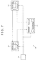
- FIG. 7 is a block diagram illustrating an exemplary configuration of an editing system practiced as a first embodiment of the invention.
- FIG. 8 is a block diagram illustrating an exemplary detail configuration of a recording machine shown in FIG. 7 ;
- FIG. 9 is a block diagram illustrating details of processing by a CPU and a video encoder
- FIG. 10 is a diagram illustrating the processing by the CPU
- FIG. 11 is another diagram illustrating the processing by the CPU
- FIG. 12 is a flowchart indicative of encoding processing except for the last GOP by the recording machine shown in FIG. 8 ;
- FIG. 13 is a flowchart indicative of encoding processing of the last GOP by the recording machine shown in FIG. 8 ;
- FIG. 14 is a flowchart indicative of details of VBV occupation amount connection processing in step S 37 shown in FIG. 13 ;
- FIG. 15 is a block diagram illustrating an exemplary configuration of an editing system practiced as a second embodiment of the invention.
- FIG. 16 is a block diagram illustrating an exemplary detail configuration of a recording machine shown in FIG. 15 ;
- FIG. 17 is a block diagram illustrating details of processing by a CPU and a video encoder
- FIG. 18 is a diagram illustrating the variable-length encoding of replacing data under the control of an encoding control portion
- FIG. 19 is another diagram illustrating the variable-length encoding of replacing data under the control of an encoding control portion
- FIG. 20 is still another diagram illustrating the variable-length encoding of replacing data under the control of an encoding control portion
- FIG. 21 is a flowchart indicative of edit encoding processing by the recording machine shown in FIG. 16 ;
- FIG. 22 is a block diagram illustrating an editing system practiced as a third embodiment of the invention.
- FIG. 23 is a block diagram illustrating an exemplary detail configuration of a recording machine shown in FIG. 22 ;
- FIG. 24 is a block diagram illustrating details of processing by a CPU and a video encoder
- FIG. 25 is a diagram illustrating effects obtained by the computation of the VBV occupation amount of a VBV occupation amount target picture in the CPU;
- FIG. 26 is a flowchart indicative of edit encoding processing of the recording machine shown in FIG. 23 ;
- FIG. 27 is a block diagram illustrating an exemplary configuration of an editing system practiced as a fourth embodiment of the invention.
- FIG. 28 is a block diagram illustrating an exemplary detail configuration of a recording machine shown in FIG. 27 ;
- FIG. 29 is a block diagram illustrating details of the processing by a CPU and a video encoder
- FIG. 30 is a flowchart indicative of editing encoding processing by a recorder shown in FIG. 27 ;
- FIG. 31 is a flowchart indicative of details of start picture processing shown in FIG. 30 ;
- FIG. 32 is a flowchart indicative of details of the encoding processing shown in FIG. 30 ;
- FIG. 33 is a flowchart indicative of details of the last picture processing shown in FIG. 30 ;
- FIG. 34 is a block diagram illustrating an exemplary configuration of hardware of a computer.
- FIG. 7 there is shown a block diagram illustrating an exemplary configuration of an editing system practiced as the first embodiment of the invention.
- An editing system 10 is made up of a recording machine 11 , a reproducing machine 12 , an editing machine 13 , and a reference signal generator 14 .
- the recording machine 11 (or the information processing apparatus) is connected to the reproducing machine 12 by a coaxial cable.
- the recording machine 11 variable-length encodes base data, such as video data, in the long-GOP-structured MPEG algorithm and records the encoded base data to a recording media loaded on the recording machine 11 .
- the recording machine 11 is connected to the editing machine 13 by a control line.
- This control line is a 9-pin cable of the RS-422 standard for example.
- the recording machine 11 transmits various signals to the editing machine 13 over the control line.
- the recording machine 11 inserts edit data transmitted from the reproducing machine 12 as an HD-SDI (High Definition Serial Digital Interface) signal into an edit range of base data recorded to the recording media.
- HD-SDI High Definition Serial Digital Interface
- the recording machine 11 computes the bit rate of the base data on a GOP basis as a local bit rate (hereafter referred to as a local bit rate) and variable-length encodes the replacing data including the edit data on the basis of the local bit rate.
- the reproducing machine 12 is connected to the editing machine 13 by the control line like the recording machine 11 .
- the reproducing machine 12 reads the data from a recording media loaded on the reproducing machine 12 as edit data and supplies the edit data to the recording machine 11 as an HD-SDI signal.
- the reproducing machine 12 transmits various signals to the editing machine 13 over the control line.
- the editing machine 13 is configured by a remote controller for example.
- the editing machine 13 transmits a control signal corresponding to a user instruction to the recording machine 11 and the reproducing machine 12 over the control line to control the recording machine 11 and the reproducing machine 12 , thereby executing insert editing.
- the editing machine 13 controls the recording machine 11 and the reproducing machine 12 to write the edit data reproduced by the reproducing machine 12 over the edit range of the base data recorded to the recording media of the recording machine 11 .
- the reference signal generator 14 generates reference signals that provide references for the timings of control, recording, and reproduction on the recording machine 11 , the reproducing machine 12 , and the editing machine 13 and supplies the generated reference signals to the recording machine 11 , the reproducing machine 12 , and the editing machine 13 .
- FIG. 8 there is shown a block diagram illustrating an exemplary detail configuration of the recording machine 11 shown in FIG. 7 .
- the recording machine 11 is made up of a CPU (Central Processing Unit) 21 , a baseband input/output processing block 22 , a video decoder 23 , a video encoder 24 , a buffer memory 25 , and a recording media 26 .
- a CPU Central Processing Unit
- baseband input/output processing block 22 the recording machine 11 is made up of a CPU (Central Processing Unit) 21 , a baseband input/output processing block 22 , a video decoder 23 , a video encoder 24 , a buffer memory 25 , and a recording media 26 .
- a CPU Central Processing Unit
- the CPU 21 controls other component blocks in units of frame or GOP on the basis of control signals and so on supplied from the editing machine 13 .
- the CPU 21 controls the recording media 26 to start reading pictures subsequent to a start picture of the GOP including the in-point from the recording media 26 .
- the CPU 21 controls the recording media 26 to stop the reading at the end of the reading of a terminal picture of the GOP including the out-point from the recording media 26 .
- the CPU 21 monitors other component blocks.
- the CPU 21 transmits a signal indicative of the information on the recording machine 11 , such as a time code, to the editing machine 13 .
- the baseband input/output processing block 22 has a selector 31 .
- the baseband input/output processing block 22 obtains edit data or base data transmitted from the reproducing machine 12 as an HD-SDI signal and supplies the obtained data to the selector 31 . It should be noted that this base data may be obtained from a device, not shown, other than the reproducing machine 12 or recorded in a memory, not shown, of the recording machine 11 .
- the baseband input/output processing block 22 supplies the a decoding result of the base data supplied from the video decoder 23 or recorded to the recording media 26 to the selector 31 .
- the selector 31 supplies the decoded base data transmitted from the reproducing machine 12 to the video encoder 24 . At the same time, under the control of the CPU 21 , the selector 31 selects one of the base data and the edit data supplied from the video decoder 23 and supplies the selected base data or edit data to the video encoder 24 as replacing data.
- the selector 31 selects the base data from the beginning of the GOP to the in-point and the base data from the out-point to the terminal and supplies the selected base data to the video encoder 24 as replacing data.
- the video decoder 23 reads the base data that is variable-length encoded by an long-GOP-structured MPEG algorithm from the buffer memory 25 and decodes the read base data.
- the video decoder 23 supplies a decoding result of the base data to the baseband input/output processing block 22 .
- the video encoder 24 variable-length encodes the replacing data or the base data supplied from the selector 31 in the long-GOP-structured MPEG algorithm. At the same time, the video encoder 24 supplies the variable-length encoded replacing data or base data to the buffer memory 25 as recording data.
- the buffer memory 25 temporarily stores the recording data supplied from the video encoder 24 . At the same time, the buffer memory 25 reads the recording data and supplies the read recording data to the recording media 26 . Further, the buffer memory 25 temporarily stores the base data supplied from the recording media 26 .
- the recording media 26 is made up of a removable media based on an optical disk or a flash memory or a mass-storage recording media based on a HDD (Hard Disk Drive), for example. Under the control of the CPU 21 , the recording media 26 records the recording data read from the buffer memory 25 to the recording media 26 . To be more specific, the recording media 26 (or the recording block) writes the replacing data read from the buffer memory 25 in the recording area in which the base data to be replaced is recorded, for example.
- HDD Hard Disk Drive
- the recording media 26 reads the recorded base data variable-length encoded by the long-GOP-structured MPEG algorithm and supplies the read base data to the buffer memory 25 .
- FIG. 9 there is shown a diagram illustrating details of the processing to be executed by the CPU 21 and the video encoder 24 in variable-length encoding replacing data.
- the CPU 21 computes a local bit rate on a GOP basis by use of the code amount and VBV delay and the like of the base data, for example, and supplies the computed local bit rate to the video encoder 24 .
- the CPU 21 computes a difference in the code amount and a difference in the VBV occupation amount between the base data and the replacing data on the basis of the code amount and VBV occupation amount of the variable-length encoded replacing data supplied from the encoding control portion 41 and the code amount and VBV occupation amount of the base data.
- the CPU 21 computes an code amount error by use of the differences of the code amount and the VBV occupation amount and, on the basis of an obtained code amount error, computes the local bit rate of the base data subsequent to the GOP corresponding to this code amount error. Namely, the CPU 21 feeds back the code amount error to the computation of the local bit rate.
- the video encoder 24 has an encoding control portion 41 for controlling the variable-length encoding of replacing data supplied from the selector 31 (refer to FIG. 8 ).
- the encoding control portion 41 executes encoding control that is finer than the control by the CPU 21 executed on frame or GOP basis.
- the encoding control portion 41 controls the variable-length encoding by the video encoder 24 on the basis of a local bit rate supplied from the CPU 21 , for example.
- the encoding control portion 41 obtains the code amount and VBV occupation amount of the variable-length encoded replacing data and supplies the obtained code amount and VBV occupation amount to the CPU 21 .
- a local bit rate is obtained on a GOP basis; however, it is also applicable to obtain a local bit rate on a frame basis for example.
- FIG. 10 and FIG. 11 illustrate the processing to be executed by the CPU 21 .
- the CPU 21 computes a local bit rate on a GOP basis. To be more specific, the CPU 21 computes a local bit rate by equation (3) below by use of the code amount and VBV delay of the base data for the start GOP in the re-encode range as shown in FIG. 11 .
- R(n) in equation (3) above is indicative of a bit rate of frame n and d(n) is indicative of a code amount of frame n; ⁇ (n) is indicative of a VBV delay of frame n; t(n) is indicative of a time at which a picture of frame n is removed from the VBV buffer; and X is indicative of the number of frames for use in the computation of a local bit rate.
- Equation (3) 1 is added to the VBV delay in the computation range of local bit rates. This makes it equal to that a VBV occupation amount has been rounded up when quantized to VBV delay. Therefore, according to equation (3) above, the local bit rate is computed smaller. Namely, an error of the local bit rate becomes an error in the direction in which the error gets smaller than an actual value. As a result, when a VBV occupation amount is connected, the code amount of replacing data gets smaller than the code amount of base data. Consequently, the replacing data can be surely stored in the recording area of the base data to be replaced.
- the CPU 21 computes code amount errors of base data and replacing data by use of equation (4) below.
- diff(n) is indicative of a code amount error of frame n
- d(n) and d′(n) are indicative of a code amount of base data and a code amount of replacing data, respectively, of frame n
- 0′(n) and 0(n) are indicative of a VBV occupation amount of base data and a VBV occupation amount of replacing data, respectively, of frame n. Therefore, d(n) ⁇ d′(n) is indicative of a difference between the code amounts of base data and replacing data and 0′(n) ⁇ 0(n) is indicative of a difference between the VBV occupation amounts of base data and replacing data.
- the replacing data can be stored in the recording area of the base data to be replaced while maintaining the continuity of VBV occupation amounts.
- the local bit rate is computed smaller so as to make the code amount error equal to or higher than 0 in each GOP, so that, as the variable-length encoding of the replacing data progresses, the code amount errors are accumulated. So, in order to make the most of the code amount unnecessary for maintaining the continuity of the VBV occupation amounts among the accumulated code amount errors, the CPU 21 feeds back the code amount error to the computation of a local bit rate for the GOPs other than the start GOP in each re-encode range as shown in equation (5) below.
- R(n) is indicative of a bit rate of frame n; d(n) is indicative of a code amount of frame n; ⁇ (n) is indicative of a VBV delay of frame n; t(n) is indicative of a time at which a picture of frame n is removed from the VBV buffer; X is indicative of the number of frames for use in computing a local bit rate; diff(n) is indicative of a code amount error of frame n; ⁇ diff(n ⁇ Y) is indicative of a sum of code amount errors from frame Y (1 ⁇ Y) to frame n; and coef is indicative of a feedback coefficient.
- the feedback executed as described above may cause a code amount error to go negative. Therefore, feedback coefficient coef must be determined in a range such that a sum of code amount errors will not go negative. It is also practicable to fix feedback coefficient coef or adaptively change feedback coefficient coef in accordance with the length of GOP for example.
- FIG. 12 there is shown a flowchart indicative of the encoding processing by the recording machine 11 for encoding other than the last GOP.
- This processing for encoding the GOPs other than the last GOP is executed for each GOP in a re-encode range other than the last GOP.
- step S 11 shown in FIG. 12 using a code amount and a VBV delay of a GOP subject to base data processing, the CPU 21 computes the local bit rate of this GOP.
- the CPU 21 computes a local bit rate in accordance with equation (3) described above.
- the CPU 21 computes the local bit rate in accordance with equation (5) above also by use of the encoding error computed by the processing of step S 16 to be described later by executing the GOP before the GOP other than the start GOP.
- step S 12 the CPU 21 determines whether the local bit rate computed in step S 11 is equal to or higher than a specified value of the format. If the local bit rate is found to be equal to or higher than the specified value of the format, then the CPU 21 corrects the local bit rate to the specified value in step S 13 . This is done to prevent the newly variable-length encoded stream from violating the format and surely store the replacing data into the recording area of the base data to be replaced. Then, the CPU 21 supplies the corrected local bit rate to the encoding control portion 41 , upon which the procedure goes to step S 14 .
- step S 12 if the local bit rate is found to be lower than the specified value of the format in step S 12 , then the CPU 21 supplies the local bit rate computed in step S 11 to the encoding control portion 41 without change. Then, the procedure goes to step S 14 .
- step S 14 under the control of the encoding control portion 41 , the video encoder 24 executes variable-length encoding on the entered replacing data on the basis of the local bit rate of the GOP subject to processing supplied from the encoding control portion 41 .
- step S 15 the encoding control portion 41 obtains the code amount and the VBV occupation amount of each frame that are the results of the variable-length encoding executed in step S 14 and supplies the obtained code amount and VBV occupation amount to the CPU 21 .
- step S 16 by use of the code amount and the VBV occupation amount of each frame supplied from the encoding control portion 41 and the code amount and the VBV occupation amount of the corresponding frame of the base data, the CPU 21 computes a code amount error of each frame from equation (4) above. This code amount error is fed back to the computation of the local bit rate of a next GOP.
- FIG. 13 there is shown a flowchart indicative of the processing of encoding the last GOP to be executed by the recording machine 11 shown in FIG. 8 .
- This last-GOP encoding processing is executed on the last GOP of each re-encode range.
- steps S 31 through S 35 are substantially the same as those steps S 11 through S 15 , so that the description of the former will be skipped.
- step S 35 the encoding control portion 41 determines in step S 36 whether the locus of the VBV occupation amount obtained by the variable-length encoding of the replacing data is connectable to the VBV occupation amount of the VBV occupation amount target picture.
- step S 36 If the locus of the VBV occupation amount is found to be connectable in step S 36 , then the encoding control portion 41 executes VBV occupation amount connection processing for connecting the VBV occupation amount in step S 37 , upon which the procedure comes to an end. It should be noted that the details of this VBV occupation amount connection processing will be described later with reference to the flowchart shown in FIG. 14 .
- step S 36 if the locus of the VBV occupation amount is found not to be connectable in step S 36 , the procedure goes to step S 38 .
- step S 38 the CPU 21 computes a code amount error in accordance with equation (5) above by use of the code amount and the VBV occupation amount of each frame obtained by the processing of step S 35 and the code amount and the VBV occupation amount of the corresponding frame of the base data.
- the CPU 21 returns the procedure to step S 31 by including a frame next to the last frame of the current re-encode range into a new last GOP. Then, until the locus of the VBV occupation amount to be obtained by the variable-length encoding of the replacing data is found to be connectable to the VBV occupation amount of the VBV occupation amount target picture, the CPU 21 repeats the processing operations of steps S 31 through S 36 and S 38 .
- FIG. 14 there is shown a flowchart indicative of the details of the VBV occupation amount connection processing of step S 37 shown in FIG. 13 .
- step S 41 shown in FIG. 14 the encoding control portion 41 predicts the VBV occupation amount of a frame next to the last frame on the basis of the local bit rate computed by feeding back the VBV occupation amount, the code amount, and the code amount error of the replacing data of the last frame in the re-encode range.
- step S 42 the encoding control portion 41 determines whether the VBV occupation amount predicted in step S 41 is higher than the computed value of the actual VBV occupation amount converted from the VBV delay stored in the frame next to the last frame in the re-encode range.
- step S 42 If the predicted VBV occupation amount is found to be higher than the computed value of the actual VBV occupation amount in step S 42 , then the encoding control portion 41 adds, in step S 43 , stuffing data to the last frame of the re-encode range after the insert editing so as to make both the VBV occupation amounts equal to each other.
- step S 44 the encoding control portion 41 recalculates the VBV delay of the frame next to the last frame of the re-encode range by use of the local bit rate used for the variable-length encoding of the re-encode range and rewrites the VBV delay. This is because the bit rate changes before or after the editing as a result of the computation of the local bit rate of the last frame with the code amount error fed back. After the end of the processing of step S 44 , the procedure comes to an end.
- the recording machine 11 computes the local bit rate of base data, so that the bit rate of replacing data follows the bit rate of base data more correctly.
- the code amount of replacing data can be surely held down equal to or below the code amount of base data while maintaining the continuity of the VBV occupation amount within a quantization error range. Consequently, the insert editing executed on related-art VTRs can be successfully executed also on the recording media to which encoded streams having the long GOP structure with variable code amount.
- the above-mentioned novel configuration allows the suppression of a wasted code amount as compared with a method in which replacing data is variable-length encoded with the bit rate thereof fixed sufficiently lower than that of base data to enhance the success rate of the editing. As a result, the deterioration of picture quality can be suppressed.
- the recording machine 11 controls the variable-length encoding not by local code amount but by bit rate, so that code amounts can be efficiently distributed in accordance with replacing data without being influenced by the code amount of base data. As a result, the deflection of picture quality can be suppressed.
- FIG. 15 there is shown a block diagram illustrating an exemplary configuration of an editing system practiced as the second embodiment of the invention.
- FIG. 15 components similar to those previously described with reference to FIG. 7 are denoted by the same reference numerals and the description thereof is skipped.
- the configuration of an editing system 100 shown in FIG. 15 is mainly different from that shown in FIG. 7 in the arrangement of a recording machine 111 instead of the recording machine 11 .
- the recording machine 111 shown in FIG. 15 is connected to a reproducing machine 12 with a coaxial cable.
- the recording machine 111 variable-length encodes base data in the long-GOP-structured MPEG algorithm and records the encoded base data to a recording media loaded on the recording machine 111 .
- the recording machine 111 is connected to an editing machine 13 with a control line like the recording machine 11 . Further, the recording machine 111 transmits various signals to the editing machine 13 over the control line like the recording machine 11 .
- the recording machine 111 inserts edit data transmitted from the reproducing machine 12 as an HD-SDI signal into the edit range of base data recorded to a recording media. It should be noted that, at this moment, the recording machine 111 sets the lower-limit and upper-limit values of a virtual VBV occupation amount by narrowing the upper-limit and lower-limit values of the VBV occupation amount corresponding to the VBV buffer by a maximum value (hereafter referred to as an error maximum value) of an error that the VBV occupation amount can take by being converted from a VBV delay. Next, the recording machine 111 executes variable-length encoding on the replacing data so as to prevent the VBV occupation amount of the replacing data from exceeding the upper-limit value or falling below the lower-limit value of the virtual VBV occupation amount.
- FIG. 16 there is shown a block diagram illustrating an exemplary detail configuration of the recording machine 111 shown in FIG. 15 .
- FIG. 16 components similar to those previously described with reference to FIG. 8 are denoted by the same reference numerals and the description thereof is skipped.
- the configuration of the recording machine 111 shown in FIG. 16 is mainly different from that shown in FIG. 8 in the arrangement of a CPU 121 and an video encoder 122 instead of the CPU 21 and the video encoder 24 .
- the CPU 121 controls other component blocks on a frame or GOP basis.
- the CPU 121 computes, as an error maximum value, a value obtained by dividing that bit rate by 90000 for example and supplies the computed error maximum value to the video encoder 122 .
- the CPU 121 controls the recording media 26 to start the reading of pictures subsequent to the start picture of the GOP including an in-point supplied from the recording media 26 .
- the CPU 121 controls the recording media 26 to stop the reading of pictures at the end of the reading of the terminal picture of the GOP including an out-point supplied from the recording media 26 .
- the CPU 121 monitors other component blocks.
- the CPU 121 transmits a signal indicative of information on the recording machine 111 , such as a time code, to the editing machine 13 .
- the video encoder 122 executes variable-length encoding on the base data supplied from the selector 31 in the long-GOP-structured MPEG algorithm. Also, on the basis of the error maximum value supplied from the CPU 121 , the video encoder 122 executes variable-length encoding on the replacing data supplied from the selector 31 in the long-GOP-structured MPEG algorithm. Like the video encoder 24 , the video encoder 122 supplies the variable-length encoded replacing data or base data to the buffer memory 25 as recording data.
- FIG. 17 illustrates details of the processing by the CPU 121 and the video encoder 122 in executing variable-length encoding on replacing data.
- the CPU 121 computes a value obtained by dividing that bit rate by 90000 for example as an error maximum value and supplies the computed error maximum value to the video encoder 122 :
- the video encoder 122 has an encoding control portion 141 for controlling the variable-length encoding of replacing data supplied from a selector 31 (refer to FIG. 16 ).
- the encoding control portion 141 executes encoding control in a unit finer than that of the control by the CPU 121 on a frame or GOP basis.
- the encoding control portion 141 uses, as a virtual upper-limit value of a VBV occupation amount, a value obtained by subtracting the error maximum value from the upper-limit value of the actual VBV occupation amount corresponding to the VBV buffer, for example.
- the encoding control portion 141 uses, as a virtual lower-value of a VBV occupation amount, a value obtained by adding the error maximum value to the lower-limit value of the actual VBV occupation amount corresponding to the VBV buffer, for example.
- the encoding control portion 141 controls the variable-length encoding of the replacing data by the video encoder 122 so as to prevent the VBV occupation amount of the replacing data from exceeding the upper-limit value or falling below the lower-limit value of the virtual VBV occupation amount.
- an error maximum value is a fixed value, such as a maximum value/90000 of the bit rate of base data; it is also practicable to provide an error maximum value that varies depending on local bit rates if the recording machine 111 computes a local bit rate as with the recording machine 11 . In this case, an error maximum value is determined for each GOP on the basis of a local bit rate.
- FIG. 18 through FIG. 20 illustrate the variable-length encoding of replacing data that is executed under the control of the encoding control portion 141 .
- dashed lines are indicative of temporal changes of the VBV occupation amount of base data.
- thick solid lines are indicative of temporal changes of the VBV occupation amount of replacing data when an occupation amount error is 0.
- thick solid lines are indicative of temporal changes of the VBV occupation amount of replacing data when an occupation amount error is not 0 and thin solid lines are indicative of temporal changes of the VBV occupation amount of replacing data if an occupation amount error is 0.
- replacing data is variable-length encoded so as not for the VBV occupation amount of replacing data to exceed the upper-limit value or falling below the lower-limit value of a virtual VBV occupation amount
- the VBV occupation amount of replacing data falls within a range from the lower-limit value of the virtual occupation amount to the upper-limit value thereof if an occupation amount error is 0 as shown in FIG. 18 .
- an occupation amount error of the start picture of a re-encode range is an error maximum value in the upward direction
- the VBV occupation amount of replacing data exceeds the upper-limit value to a virtual VBV occupation amount.
- the occupation amount error of the VBV occupation amount of the start picture is an error maximum value
- the VBV occupation amount of replacing data does not exceed the upper-limit value of the actual VBV occupation amount corresponding to the VBV buffer. Therefore, no overflow occurs.
- the occupation amount error of the start picture of a re-encode range is an error maximum value in the downward direction
- the VBV occupation amount of replacing data falls below the lower-limit value of the virtual VBV occupation amount.
- the occupation amount error of the VBV occupation amount of the start picture is an error maximum value
- the VBV occupation amount of replacing data does not fall below the lower-limit value of the actual VBV occupation amount corresponding to the VBV buffer. Therefore, no underflow occurs.
- the recording machine 111 executes variable-length encoding on replacing data by narrowing the upper-limit and lower-limit values of the actual VBV occupation amount corresponding to the VBV buffer by an error maximum value, so that, if an occupation amount error caused by the conversion from the VBV delay is a maximum value, the locus of the VBV occupation amount of replacing data does not exceed the upper-limit value or the lower-limit value of the actual VBV occupation amount. Therefore, neither underflow nor overflow occurs in the edited data.
- variable-length encoding may be executed on replacing data by leaving the upper-limit and lower-limit values of the VBV occupation amount of the start picture to the upper-limit and lower-limit values of the actual VBV occupation amount.
- the upper-limit and lower-limit values of the VBV occupation amount of the pictures subsequent to the start picture may be set to the upper-limit and lower-limit values of the virtual VBV occupation amount.
- one of the upper-limit and lower-limit values of the VBV occupation amount of the pictures subsequent to the start picture may be set to the VBV occupation amount of the start picture. Obviously, it is practicable not to execute the variable-length encoding itself on replacing data.
- VBV occupation amount connection processing may be executed without change or variable-length encoding may be continued until the VBV occupation amount target picture becomes a picture that corresponds to a VBV occupation amount that does not exceed the upper-limit value and does not fall below the lower-limit value, either, of the virtual VBV occupation amount.
- the encoding control portion 141 may correct this upper-limit value or this lower-limit value to the VBV occupation amount of the start picture; if the VBV occupation amount of the VBV occupation amount target picture is in excess of the upper-limit value or the lower-limit value of the virtual VBV occupation amount, then the encoding control portion 141 may correct this upper-limit value or this lower-limit value to the VBV occupation amount of the VBV occupation amount target picture.
- FIG. 21 there is shown a flowchart indicative of edit encoding processing to be executed by the recording machine 111 shown in FIG. 16 .
- This edit encoding processing is started when replacing data is entered in the video encoder 122 , for example.
- step S 111 shown in FIG. 21 the CPU 121 (refer to FIG. 17 ) determines whether a VBV occupation amount having bit precision is obtainable from the variable-length encoded base data.
- the encoding control portion 141 may make this determination in accordance with an input made externally or by analyzing the variable-length encoded base data.
- step S 111 If the VBV occupation amount having bit precision is found to be unobtainable in step S 111 , then the CPU 121 computes an error maximum value from the maximum value of the bit rate of the base data included in the variable-length encoded based data and supplies the computed error maximum value to the encoding control portion 141 .
- step S 112 on the basis of the error maximum value supplied from the CPU 121 , the encoding control portion 141 computes the upper-limit and lower-limit values of a virtual VBV occupation amount. Then, the procedure goes to step S 113 .
- step S 111 if the VBV occupation amount having bit precision is found to be obtainable in step S 111 , then the procedure goes to step S 113 .
- step S 112 the video encoder 122 executes, in step S 113 , variable-length encoding on the replacing data under the control of the encoding control portion 141 so as to prevent the VBV occupation amount from exceeding the upper-limit value or falling below the lower-limit value of the virtual VBV occupation amount. If the processing of step S 112 has not been executed, the video encoder 122 , under the control of the encoding control portion 141 , executes variable-length encoding on the replacing data so as to prevent the VBV occupation amount from exceeding the upper-limit value or falling below the lower-limit value of the actual VBV occupation amount corresponding to VBV buffer.
- step S 114 the video encoder 122 determines whether the variable-length encoded picture is the last picture of the re-encode range or not. If the variable-length encoded picture is found to be not the last picture of the re-encode range in step S 114 , then the procedure returns to step S 113 to repeat the processing operations of step S 113 and step S 114 until the variable-length encoded picture becomes the last picture of the re-encode range.
- step S 115 the encoding control portion 141 determines whether the locus of the VBV occupation amount obtained by the variable-length encoding of the replacing data is connectable with the VBV occupation amount of the VBV occupation amount target picture.
- step S 115 If the locus of the VBV occupation amount is found to be connectable in step S 115 , then the encoding control portion 141 executes the VBV occupation amount connection processing shown in FIG. 14 in step S 116 .
- step S 115 the encoding control portion 141 includes, in the re-encode range, a frame next to the last frame of the current re-encode range and returns the procedure to step S 113 . Then, the processing operations of step S 113 through step S 115 are repeated until the locus of the VBV occupation amount obtained by the variable-length encoding of the replacing data is found to be connectable with the VBV occupation amount of the VBV occupation amount target picture.
- the above-mentioned processing allows the recording machine 111 to execute insert editing also on an encoded stream with which the VBV occupation amount of bit precision having the long GOP structure cannot be obtained without involving VBV buffer overflow or underflow. Consequently, the insert editing practiced on related-art VTRs can be surely and successfully executed also on recording media on which encoded streams having the log GOP structure of variable code amounts are recorded.
- FIG. 22 there is shown a block diagram illustrating an exemplary configuration of an editing system practiced as the third embodiment of the invention.
- the configuration of an editing system 200 shown in FIG. 22 is mainly different from that shown in FIG. 7 in the arrangement of a recording machine 211 instead of the recording machine 11 .
- the recording machine 211 shown in FIG. 22 is connected to a reproducing machine 12 with a coaxial cable like the recording machine 11 shown in FIG. 7 .
- the recording machine 211 variable-length encodes base data in the long-GOP-structured MPEG algorithm and records the encoded base data to a recording media loaded on the recording machine 211 .
- the recording machine 211 is connected to an editing machine 13 with a control line like the recording machine 11 . Further, like the recording machine 11 , the recording machine 211 transmits various signals to the editing machine 13 over the control line.
- the recording machine 211 inserts edit data transmitted from the reproducing machine 12 as an HD-SDI signal into the edit range of base data recorded to the recording media. It should be noted that, at this moment, the recording machine 211 computes the VBV occupation amount of a VBV occupation amount target picture from a value obtained by adding 1 to the VBV delay of the VBV occupation amount target picture and variable-length encodes the replacing data on the basis of the computed VBV occupation amount.
- FIG. 23 there is shown a block diagram illustrating an exemplary detail configuration of the recording machine 211 shown in FIG. 22 .
- FIG. 23 components similar to those previously described with reference to FIG. 8 are denoted by the same reference numerals and the description thereof is skipped.
- the configuration of the recording machine 211 shown in FIG. 23 is mainly different from the configuration shown in FIG. 8 in that a CPU 221 and a video encoder 222 are arranged instead of the CPU 21 and the video encoder 24 .
- the CPU 221 controls other component blocks on a frame or GOP basis.
- the CPU 221 (the computation block) computes the VBV occupation amount of a VBV occupation amount target picture from a value obtained by adding 1 to the VBV delay of the VBV occupation amount target picture and supplies the computed VBV occupation amount to a video encoder 222 .
- the CPU 221 controls a recording media 26 on the basis of a control signal indicative of a user-specified in-point supplied from the editing machine 13 to start the reading of pictures subsequent to the start picture of a GOP including an in-point supplied from the recording media 26 .
- the CPU 221 controls the recording media 26 on the basis of a control signal indicative of a user-specified out-point supplied from the editing machine 13 to stop the reading of the pictures subsequent to the start picture upon the end of the reading of the terminal picture of the GOP including an out-point supplied from the recording media 26 .
- the CPU 221 monitors the other component blocks.
- the CPU 221 transmits a signal indicative of information on the recording machine 211 , such as a time code, to the editing machine 13 .
- the video encoder 222 variable-length encodes the base data supplied from the selector 31 in the long-GOP structured MPEG algorithm. Also, on the basis of the VBV occupation amount of the VBV occupation amount target picture supplied from the CPU 221 , the video encoder 222 variable-length encodes the replacing data supplied from the selector 31 in the long-GOP-structured MPEG algorithm. Moreover, like the video encoder 24 shown in FIG. 8 , the video encoder 222 supplies the variable-length encoded replacing data or base data to a buffer memory 25 as recording data.
- FIG. 24 there is shown a diagram illustrating details of the processing by the CPU 221 and the video encoder 222 .
- the CPU 221 computes the VBV occupation amount of a VBV occupation amount target picture from a value obtained by adding 1 to the VBV delay of the VBV occupation amount target picture and supplies the computed VBV occupation amount to the video encoder 222 .
- the video encoder 222 has an encoding control portion 241 for controlling the variable-length encoding of replacing data supplied from the selector 31 (refer to FIG. 23 ).
- the encoding control portion 241 executes encoding control in a unit finer than that of the control by the CPU 221 on a frame or GOP basis.
- the encoding control portion 241 controls the variable-length encoding of replacing data by the video encoder 222 (the encoding block) so as to the VBV occupation amount of the last picture of replacing data connects to the VBV occupation amount of the VBV occupation amount target picture supplied from the CPU 221 , for example.
- the computation of the VBV occupation amount of the VBV occupation amount target picture from a value obtained by adding 1 to the VBV delay of the VBV occupation amount target picture is equivalent to the rounding up that is executed when the VBV occupation amount is quantized into the VBV delay. Therefore, the variable-length encoding of the replacing data on the basis of the VBV occupation amount of the VBV occupation amount target picture thus computed prevents the code amount of the replacing data from exceeding the code amount of the base data even if the VBV occupation amount has an occupation amount error. It should be noted that the handling of decimal places at the quantization of the VBV delay is not specified by the standard concerned.
- FIG. 25 there is shown a diagram illustrating effects of the VBV occupation amount of VBV occupation amount target picture in the CPU 221 .
- the CPU 221 computes the VBV occupation amount of a VBV occupation amount target picture from a value obtained by adding 1 to the VBV delay of the VBV occupation amount target picture, so that, as shown in FIG. 25 , the VBV occupation amount of the last picture has an occupation amount error in the upward direction. Accordingly, if the VBV occupation amount of the start picture of a re-encode range has an occupation amount error in the downward direction, a code amount of base data remains by an occupation amount error between both of the start picture and the last picture, so that the code amount of replacing data does not exceed the code amount of base data.
- VBV occupation amount of a VBV occupation amount target picture from a value obtained by adding 1 to the VBV delay of the VBV occupation amount target picture exceeds the upper-limit value or falls below the lower-limit value of the actual VBV occupation amount corresponding to the VBV buffer, the re-encode range is extended until this VBV occupation amount does not exceed the upper-limit value and does not fall below lower-limit value, either.
- FIG. 26 is a flowchart indicative of the edit encoding processing to be executed by the recording machine 211 shown in FIG. 23 .
- This edit encoding processing starts when replacing data is entered in the video encoder 222 , for example.
- step S 211 shown in FIG. 26 the CPU 221 (refer to FIG. 24 ) computes a VBV occupation amount of the start picture of the re-encode range and supplies the computed VBV occupation amount to the encoding control portion 241 .
- step S 212 under the control of the encoding control portion 241 , the video encoder 222 variable-length encodes replacing data such that the VBV buffer will not overflow or underflow with the VBV occupation amount computed in step S 211 used as the origin.
- step S 213 the video encoder 222 determines whether the encoded picture is the last picture of the re-encode range or not. If the encoded picture is found not to be the last picture of the re-encode range in step S 213 , then the procedure is returned to step S 212 to repeat the processing operations of step S 212 and S 213 until the encoded picture becomes the last picture of the re-encoded range.
- step S 213 the CPU 221 computes the VBV occupation amount of a VBV occupation amount target picture from a value obtained by adding 1 to the VBV delay of the VBV occupation amount target picture and supplies the computed VBV occupation amount to the encoding control portion 241 .
- step S 214 the encoding control portion 241 determines whether the VBV occupation amount of the VBV occupation amount target picture computed from the value obtained by adding 1 to the VBV delay of the VBV occupation amount target picture supplied from the CPU 221 has exceeded the upper-limit value of the actual VBV occupation amount corresponding to the VBV buffer.
- step S 214 If the VBV occupation amount of the VBV occupation amount target picture is found not exceeding the upper-limit value of the actual VBV occupation amount of the VBV occupation amount target picture in step S 214 , then the procedure goes to step S 215 .
- step S 215 the encoding control portion 241 determines whether the locus of the VBV occupation amount obtained by the variable-length encoding of replacing data is connectable to the VBV occupation amount of the VBV occupation amount target picture.
- step S 215 If the locus of the VBV occupation amount is found to be connectable in step S 215 , then the encoding control portion 241 executes the VBV occupation amount connection processing shown in FIG. 14 to end the above-mentioned processing in step S 216 .
- encoding control portion 241 includes a frame next to the last frame of the current re-encode range into a re-encode range to return the procedure to step S 212 .
- step S 212 through step S 215 are repeated until the VBV occupation amount of the VBV occupation amount target picture does not exceed the upper-limit of the actual VBV occupation amount and the locus of the VBV occupation amount obtained by the variable-length encoding of the replacing data is found connectable to the VBV occupation amount of the VBV occupation amount target picture.
- the edit encoding processing may be executed only if there is a match between the bit rate of base data and the bit rate of replacing data.
- the above-mentioned processing allows the recording machine 211 to surely store the replacing data in the recording area of the base data to be replaced if there is a match between the bit rate of the base data and the bit rate of the replacing data. Consequently, the insert editing practiced on related-art VTRs can be surely and successfully executed also on recording media on which encoded streams having the log GOP structure of variable code amounts are recorded.
- the recording machine 211 may set the upper-limit and lower-limit values of a virtual VBV occupation amount.
- the encoding control portion 241 determines in step S 214 whether the VBV occupation amount of the VBV occupation amount target picture has exceeded the upper-limit value of the virtual VBV occupation amount.
- FIG. 27 there is shown a block diagram illustrating an exemplary configuration of an editing system practiced as the fourth embodiment of the invention.
- FIG. 27 components similar to those previously described with reference to FIG. 7 are denoted by the same reference numerals and the description thereof is skipped.
- the configuration of an editing system 250 shown in FIG. 27 is mainly different from the configuration shown in FIG. 7 in that a recording machine 251 is arranged instead of the recording machine 11 .
- the recording machine 251 shown in FIG. 27 is connected to a reproducing machine 12 with coaxial cable.
- the recording machine 251 variable-length encodes base data in the long-GOP-structured MPEG algorithm and records the encoded base data to a recording media loaded on the recording machine 251 .
- the recording machine 251 is connected to an editing machine 13 with a control line. Further, like the recording machine 11 , the recording machine 251 transmits various signals to the editing machine 13 over the control line.
- the recording machine 251 inserts edit data transmitted from the reproducing machine 12 as an HD-SDI signal into the edit range of the base data recorded to the recording media.
- the recording machine 251 executes substantially the same processing that is executed by the recording machine 11 , the recording machine 111 , and recording machine 211 .
- recording machine 251 computes the bit rate of base data on a GOP basis as a local bit rate.
- the recording machine 251 sets the upper-limit and lower-limit values of a virtual VBV occupation amount by narrowing the upper-limit and lower-limit values of a VBV occupation amount corresponding to the VBV buffer by an error maximum value.
- the recording machine 251 computes the VBV occupation amount of a VBV occupation amount target picture from a value obtained by adding 1 to a VBV delay of the VBV occupation amount target picture. Then, on the basis of the local bit rate, the upper-limit and lower-limit values of virtual VBV occupation amount, and the VBV occupation amount of VBV occupation amount target picture, the recording machine 251 variable-length encodes the replacing data that includes edit data.
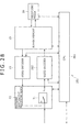
- FIG. 28 there is shown a block diagram illustrating an exemplary detail configuration of the recording machine 251 shown in FIG. 27 .
- FIG. 28 components similar to those previously described with reference to FIG. 8 are denoted by the same reference numerals and the description thereof is skipped.
- the configuration of the recording machine 251 shown in FIG. 28 is mainly different from the configuration shown in FIG. 8 in that a CPU 261 and a video encoder 262 are arranged instead of the CPU 21 and the video encoder 24 .
- the CPU 261 controls other component blocks on a frame or GOP basis on the basis of controls signals and so on supplied from an editing machine 13 .
- the CPU 261 (the computation block) computes a local bit rate on a GOP basis by use of a code amount of base data, a VBV delay, and so on, and supplies the computed local bit rate to the video encoder 262 . Also, on the basis of the local bit rate, the CPU 261 computes a value obtained by dividing this local bit rate by 90000 for example as a VBV occupation amount error value and supplies this error to the video encoder 262 . Further, the CPU 261 computes the VBV occupation amount of a VBV occupation amount target picture from a value obtained by adding 1 to the VBV delay of the VBV occupation amount target picture and supplies the computed VBV occupation amount to the video encoder 262 .
- the CPU 261 controls a recording media 26 on the basis of a control signal indicative of a user-specified in-point supplied from the editing machine 13 to start the reading of pictures subsequent to the start picture of the GOP including an in-point supplied from the recording media 26 .
- the CPU 261 controls the recording media 26 on the basis of control signal indicative of a user-specified out-point supplied from the editing machine 13 to stop the reading of the pictures subsequent to the start picture upon the end of the reading of the terminal picture of the GOP including an out-point supplied from the recording media 26 .
- the CPU 261 monitors the other component blocks.
- the CPU 261 transmits a signal indicative of information on the recording machine 251 , such as a time code, to the editing machine 13 .
- the video encoder 262 variable-length encodes the base data supplied from the selector 31 in the long-GOP structured MPEG algorithm. Also, on the basis of the local bit rate, the VBV occupation amount error value and the VBV occupation amount of the VBV occupation amount target picture supplied from the CPU 261 , the video encoder 262 variable-length encodes the replacing data supplied from the selector 31 in the long-GOP-structured MPEG algorithm. Moreover, like the video encoder 24 shown in FIG. 8 , the video encoder 262 supplies the variable-length encoded replacing data or base data to a buffer memory 25 as recording data.
- FIG. 29 there is shown a diagram illustrating details of the processing by the CPU 261 and the video encoder 262 in variable-length encoding replace data.
- the CPU 261 computes a code amount error on the basis of the code amount and VBV occupation amount of variable-length encoded replacing data supplied from a encoding control portion 271 and the code amount and VBV occupation amount of base data. Then, like the CPU 21 , the CPU 261 computes a local bit rate on a GOP basis by use of the code amount of base data, a VBV delay, and a code amount error and supplies computed local bit rate to the video encoder 262 .
- the CPU 261 computes a value obtained by dividing this local bit rate by 90000 for example as a VBV occupation amount error and supplies this error to the video encoder 262 . Further, like the CPU 221 shown in FIG. 24 , the CPU 261 computes the VBV occupation amount of a VBV occupation amount target picture from a value obtained by adding 1 to the VBV delay of the VBV occupation amount target picture and supplies the computed VBV occupation amount to the video encoder 262 .
- the video encoder 262 has an encoding control portion 271 for controlling the variable-length encoding of replacing data supplied from the selector 31 (refer to FIG. 28 ).
- the encoding control portion 271 executes encoding control in a unit finer than that of the control by the CPU 261 on a frame or GOP basis.
- the encoding control portion 271 uses, as a virtual upper-limit value of a VBV occupation amount, a value obtained by subtracting a VBV occupation amount error value from the upper-limit value of an actual VBV occupation amount corresponding to the VBV buffer on the basis of a VBV occupation amount error value supplied from the CPU 261 , for example. Also, the encoding control portion 271 uses, as a virtual lower-limit value of a VBV occupation amount, a value obtained by adding a VBV occupation amount error value to the lower-limit value of an actual VBV occupation amount corresponding to the VBV buffer on the basis of a VBV occupation amount error value supplied from the CPU 261 , for example.
- the encoding control portion 271 controls the variable-length encoding of the replacing data by the video encoder 262 (the encoding block) such that the VBV occupation amount of the replacing data does not exceed the upper-limit value and does not fall below the lower-limit value, either, of the virtual VBV occupation amount and the VBV occupation amount of the last picture of the replacing data connects to the VBV occupation amount of the VBV occupation amount target picture supplied from the CPU 261 .
- the encoding control portion 271 acquires the code amount and the VBV occupation amount of the variable-length encoded replacing data and supplies the obtained code amount and VBV occupation amount to the CPU 261 .
- FIG. 30 there is shown a flowchart indicative of the edit encoding processing to be executed by the recording machine 251 shown in FIG. 27 .
- This edit encoding processing starts when replacing data is entered in the video encoder 262 , for example.
- step S 311 shown in FIG. 30 the recording machine 251 executes start-picture processing that is associated with the start-picture of a re-encode range. Details of this start picture processing will be described later with reference to FIG. 31 .
- step S 312 the recording machine 251 executes encoding processing on replacing data. Details of this encoding processing will be described later with reference to FIG. 32 .
- step S 313 the recording machine 251 executes last picture processing associated with the last picture of the re-encode range. Details of this last picture processing will be described later with reference to FIG. 33 .
- FIG. 31 there is shown a flowchart indicative of the details of the start-picture processing of step S 311 shown in FIG. 30 .
- step S 331 shown in FIG. 31 the CPU 261 (refer to FIG. 28 ) determines whether a VBV occupation amount having the bit precision of the start picture is obtainable from the variable-length encoded base data.
- the encoding control portion 271 may make this decision in response to an input externally made or by analyzing the variable-length encoded base data.
- step S 331 If the VBV occupation amount having the bit precision is found to be unobtainable in step S 331 , then the procedure goes to step S 332 , In step S 332 , the CPU 261 computes a local bit rate of a start GOP from equation (3) above by use of the code amount and a VBV delay of the base data of the start GOP of re-encode range.
- step S 333 the CPU 261 determines whether the local bit rate computed in step S 332 is equal to or higher than a format specified value. If the local bit rate is found to be equal to or higher than the format specified value in step S 333 , then the CPU 261 corrects the local bit rate to the specified value in step S 334 and supplies the corrected local bit rate to the encoding control portion 271 . At the same time, the CPU 261 computes a value obtained by dividing the corrected local bit rate by 90000 as a VBV occupation amount error value and supplies the computed error value to the encoding control portion 271 . Next, the procedure goes to step S 335 .
- step S 333 if the local bit rate is found to be not equal to or higher than the format specified value in step S 333 , then the CPU 261 supplies the local bit rate computed in step S 332 to the encoding control portion 271 without change. Also, the CPU 261 computes a value obtained by dividing the corrected local bit rate by 90000 as a VBV occupation amount error value and supplies the computed error value to the encoding control portion 271 . Then, the procedure goes to step S 335 .
- step S 335 the encoding control portion 271 computes the upper-limit and lower-limit values of a virtual VBV occupation amount of the VBV buffer on the basis of the VBV occupation amount error value supplied from the CPU 261 and supplies the computed upper-limit and lower-limit values to the CPU 261 .
- step S 336 the CPU 261 computes a VBV occupation amount of the start picture on the basis of the VBV delay of the base data of the start picture of the re-encode range and the local bit rate of the start GOP.
- step S 337 the CPU 261 determines whether the VBV occupation amount of the start picture of the re-encode range exceeds the upper-limit value or falls below the lower-limit value of the virtual VBV occupation amount supplied from the encoding control portion 271 .
- the CPU 261 supplies the VBV occupation amount of the start picture of the re-encode range to the encoding control portion 271 .
- step S 338 the encoding control portion 271 changes the upper-limit value or the lower-limit value of the virtual VBV occupation amount exceeded or fell below by the VBV occupation amount of the start picture of the re-encode range to the VBV occupation amount of the start picture of the re-encode range.
- the encoding control portion 271 predicts that the VBV buffer will not underflow or overflow if the VBV occupation amount is within the VBV occupation amount of the start picture. Then, the encoding control portion 271 changes the upper-limit value or the lower-limit value of the virtual VBV occupation amount exceeded by the VBV occupation amount of the start picture of the re-encode range to the VBV occupation amount of the start picture of the re-encode range. As a result, the picture quality deterioration due to the narrowing of the allowable range of VBV occupation amount can be avoided while preventing the VBV buffer underflow or overflow from happening.
- step S 338 After the processing of step S 338 , the procedure returns to step S 311 shown in FIG. 30 , from which the procedure goes to step S 312 .
- the encoding control portion 271 may regard that there is a possibility for the VBV buffer to overflow or underflow, thereby ending the edit encoding processing without executing the processing of step S 338 .
- step S 337 if the VBV occupation amount of the start picture of the re-encode range is found to not exceed the upper-limit value and not fall below the lower-limit value in step S 337 , then the procedure returns to step S 311 shown in FIG. 30 , from which the procedure goes to step S 312 .
- step S 331 If the VBV occupation amount having bit precision is found to be obtainable in step S 331 , then the CPU 261 computes a VBV occupation amount of the start picture of the re-encode range from equation (2) above on the basis of a VBV delay and so on in step S 339 . Then, the procedure returns to step S 311 shown in FIG. 30 , from which the procedure goes to step S 312 .
- FIG. 32 there is shown a flowchart indicative of the details of the encoding processing of step S 312 shown in FIG. 30 .
- This encoding processing is executed on a GOP basis.
- step S 351 shown in FIG. 32 by use of a code amount and a VBV delay of the base data of a GOP subject to processing in the re-encode range, the CPU 261 computes a local bit rate of this GOP. It should be noted that, in the first processing of step S 351 , the start GOP of the re-encode range is regarded as the GOP subject to processing.
- step S 352 the CPU 261 determines whether the local bit rate computed in step S 351 is equal to or higher than the format specified value or not. If the local bit rate is found to be equal to or higher than the format specified value in step S 352 , then the CPU 261 corrects the local bit rate to the specified value in step S 353 and supplies the corrected local bit rate to the encoding control portion 271 . At the same time, the CPU 261 computes a value obtained by dividing the corrected local bit rate by 90000 as a VBV occupation amount error value and supplies this error value to the encoding control portion 271 . Then, the procedure goes to step S 354 .
- step S 352 if the local bit rate is found to be not higher than the format specified value in step S 352 , then the CPU 261 supplies the local bit rate computed in step S 351 to the encoding control portion 271 without change. At the same time, the CPU 261 computes a value obtained by dividing this local bit rate by 90000 as a VBV occupation amount error value and supplies the computed error value to the encoding control portion 271 . Then, the procedure goes to step S 354 .
- step S 354 the encoding control portion 271 determines whether the GOP subject to processing is the start GOP of the re-encode range or not. If the GOP subject to processing is found not to be the start GOP of the re-encode range in step S 354 , then the procedure goes to step S 355 .
- step S 355 the encoding control portion 271 computes the upper-limit and lower-limit values of a virtual VBV occupation amount on the basis of the VBV occupation amount error value of the GOP subject to processing supplied from the CPU 261 .
- the encoding control portion 271 computes the upper-limit value and lower-limit value of the virtual VBV occupation amount on the basis of a local bit rate, so that the upper-limit value and lower-limit value of the virtual VBV occupation amount can be set more correctly. As a result, the picture quality deterioration owing to the narrowed allowable range of VBV occupation amount can be suppressed while preventing an underflow or an overflow of the VBV buffer from happening.
- the procedure goes to step S 356 .
- step S 354 if the GOP subject to processing is found to be the start GOP of the re-encode range in step S 354 , then the procedure goes to step S 356 by skipping step S 355 .
- step S 356 under the control of the encoding control portion 271 , the video encoder 262 executes variable-length encoding on replacing data.
- the video encoder 262 executes, on the basis of the local bit rate, variable-length encoding on the replacing data such that the VBV occupation amount does not exceed the upper-limit value and does not fall below the lower-limit value of the virtual VBV occupation amount.
- the video encoder 262 executes, on the basis of the local bit rate, variable-length encoding on the replacing data such that the VBV occupation amount does not exceed the upper-limit value and does not fall below the lower-limit value of the actual VBV occupation amount corresponding to the VBV buffer.
- step S 357 the encoding control portion 271 gets the code amount and VBV occupation amount of each frame obtained by the execution of variable-length encoding and supplies the obtained code amount and VBV occupation amount to the CPU 261 .
- step S 358 the video encoder 262 determines whether the GOP subject to processing is the last GOP of the re-encode range. If the GOP subject to processing is found not to be the last GOP of the re-encode range in step S 358 , then the procedure goes to step S 359 .
- step S 359 the CPU 261 computes a code amount error of each frame from equation (4) above by use of the code amount and VBV occupation amount of each frame supplied from the encoding control portion 271 and the code amount and VBV occupation amount of each frame corresponding to the base data.
- the VBV occupation amount of the base data of the start picture of the re-encode range is one that was computed by the processing of step S 336 or step S 339 .
- the VBV occupation amounts of other pictures are computed on the basis of the local bit rate and VBV delay of the GOP including these pictures.
- step S 359 After the processing of step S 359 , the CPU 261 sets a GOP next to the current GOP subject processing to the GOP to be processed next, upon which the procedure returns to step S 351 . At this moment, in the processing of step S 351 , a local bit rate is computed also by use of the code amount error computed by the processing of step S 359 . Then, the above-mentioned processing of step S 351 and on is repeated.
- step S 358 if the GOP subject to processing is found to be the last GOP of the re-encode range in step S 358 , then the procedure returns to step S 312 , from which the procedure goes to step S 313 .
- FIG. 33 there is shown a flowchart indicative of the details of the last picture processing of step S 313 shown in FIG. 30 .
- step S 361 shown in FIG. 33 the CPU 261 computes the local bit rate of the GOP next to the last GOP of the re-encode range by use of the code amount and VBV delay of the base data of this GOP next to the last GOP.
- step S 362 determines in step S 362 whether the local bit rate computed in step S 361 is equal to or higher than the format specified value or not. If the local bit rate is found to be equal to or higher than the format specified value in step S 362 , then the CPU 261 corrects the local bit rate to the specified value in step S 363 and supplies the corrected local bit rate to the encoding control portion 271 . At the same time, the CPU 261 computes a value obtained by dividing the corrected local bit rate by 90000 as a VBV occupation amount error value and supplies the computed error value to the encoding control portion 271 . Then, the procedure goes to step S 364 .
- step S 362 if the local bit rate is found not to be equal to or higher than the format specified value in step S 362 , then the CPU 261 supplies the local bit rate computed in step S 361 to the encoding control portion 271 without change. At the same time, the CPU 261 computes a value obtained by dividing the local bit rate by 90000 as a VBV occupation amount error value and supplies the computed error value to the encoding control portion 271 . Then, the procedure goes to step S 364 .
- step S 364 the CPU 261 computes a VBV occupation amount of a VBV occupation amount target picture from the local bit rate of the base data of the GOP next to the last GOP of the re-encode range supplied from the encoding control portion 271 and a value obtained by adding 1 to VBV delay of the VBV occupation amount target picture. Then, the CPU 261 supplies the computed VBV occupation amount to the encoding control portion 271 .
- step S 365 the encoding control portion 271 determines whether the VBV occupation amount of the VBV occupation amount target picture computed in step S 364 exceeds the upper-limit value of the virtual VBV occupation amount of the last GOP of the re-encode range.
- step S 365 If the VBV occupation amount of the VBV occupation amount target picture is found not exceeding the upper-limit value of the virtual VBV occupation amount of the last GOP of the re-encode range in step S 365 , then the procedure goes to step S 366 .
- step S 366 the encoding control portion 271 predicts the VBV occupation amount of the VBV occupation amount target picture on the basis of the VBV occupation amount and code amount of the replacing data of the last picture of the re-encode range and the local bit rate of the last GOP.
- step S 367 the encoding control portion 271 determines whether the VBV occupation amount predicted in step S 366 is higher than the computed value of the actual VBV occupation amount computed in step S 364 .
- the encoding control portion 271 adds stuffing data to the replacing data of the last picture of the re-encode range such that both the VBV occupation amounts become equal to each other.
- step S 369 the encoding control portion 271 re-computes the VBV delay of the VBV occupation amount target picture by use of the local bit rate used for the variable-length encoding of the re-encode range and rewrites the local bit rate.
- the procedure returns to step S 313 shown in FIG. 30 , upon which the above-mentioned processing comes to an end.
- step S 370 if the VBV occupation amount of the VBV occupation amount target value is found to exceed the virtual upper-limit value in step S 365 or if the VBV occupation amount predicted in step S 367 is found to be equal to or less than the computed value of the actual VBV occupation amount, then the procedure goes to step S 370 .
- step S 370 on the basis of the local bit rate computed in step S 361 , the encoding control portion 271 variable-length encodes the base data of the frame next to the last frame of the re-encode range such that the upper-limit of the virtual VBV occupation amount value is not exceeded and the lower-limit value of the virtual VBV occupation amount is not fell below.
- the encoding control portion 271 sets this frame next to the last frame to a new last frame of the re-encode range. Then, the procedure returns to step S 361 to repeat the above-mentioned processing therefrom.
- step S 364 if the VBV occupation amount of the VBV occupation amount target picture is found to exceed the virtual upper-limit value or fall below the virtual lower-limit value after the processing of step S 364 , then, if the VBV occupation amount is within the VBV occupation amount of that VBV occupation amount target picture, it may be predicted that the VBV buffer will not underflow or overflow, thereby executing the processing of step S 366 through S 370 .
- the recording machine 11 ( 111 , 211 , or 251 ) matches the VBV occupation amounts before and after the insert editing by adding stuffing data to the last picture of the re-encode range after the insert editing. Therefore, the recording machine 11 ( 111 , 211 , or 251 ) can start the encoding processing other than the last GOP or the edit encoding processing at the point of time when an in-point is specified by the user without waiting for the specification of an out-point.
- the VBV occupation amount of replacing data is prevented from exceeding the virtual upper-limit value and falling below the virtual lower-limit value at the time of variable-length encoding of the replacing data. It is also practicable to prevent the VBV occupation amount of base data from exceeding the virtual upper-limit value and falling below the virtual lower-limit value based on an error maximum value at the time of variable-length encoding of the base data.
- replacing data is variable-length encoded such that the code amount of replacing data is matched with the code amount of base data when round-up processing has been executed in quantizing a VBV occupation amount into a VBV delay.
- replacing data is variable-length encoded such that the remainder of the division for the VBV occupation amount of replacing data is quantized into a VBV delay becomes zero. Therefore, if the insert editing of the same editing range is executed again, the code amounts before and after the insert editing match each other, not decreasing the code amount due to the insert editing.
- the above-mentioned novel technology is also applicable to an editing system configured to execute insert editing in which a predetermined range of a TS (Transport Stream) transmitted from an external device is transmitted after replacing the predetermined range with variable-length encoded replacing data.
- TS Transport Stream
- the encoding in the present technology is not limited to the long-GOP-structured MPEG algorithm; namely, the encoding in the present technology may be any one of ISO-IEC 13838-2/ITU-TH.262, ISO-IEC 14496-10/ITU-TH.264, ISO-IEC 13818-1/ITU-T H222.0, and other highly efficient encoding schemes, for example.
- FIG. 34 there is shown a block diagram illustrating an exemplary hardware configuration of a computer that executes a sequence of processing operations of the above-mentioned recording machine 11 ( 111 , 211 , or 251 ).
- a CPU Central Processing Unit
- ROM Read Only Memory
- RAM Random Access Memory
- the bus 304 is further connected to an input/output interface 305 .
- the input/output interface 305 is connected to an input block 306 , an output block 307 , a storage block 308 , a communication block 309 , and a drive 310 .
- the input block 306 is made up of a keyboard, a mouse, and a microphone, for example.
- the output block 307 is made up of a display monitor and a loudspeaker, for example.
- the storage block 308 is based on a hard disk and nonvolatile memory, for example.
- the communication block 309 is based on a network interface for example.
- the drive 310 drives a removable media 311 such as a magnetic disk, an optical disk, a magneto-optical disk, or a semiconductor device.
- the CPU 301 loads a program from the storage block 308 into the RAM 303 via the input/output interface 305 and the bus 304 to execute the program, thereby executing the sequence of processing operations described above.
- Programs to be executed by the computer can be provided as recorded to the removable media 311 as a package media, for example.
- programs can be provided through wired or wireless transmission media, such as a local area network, the Internet, or digital satellite broadcasting, for example.
- each program can be installed in the storage block 308 through the input/output interface 305 by loading the removable media 311 on the drive 310 .
- each program can be installed in the storage block 308 by receiving through the communication block 309 via a wired or wireless transmission media.
- each program can be installed beforehand in the ROM 302 or the storage block 308 to be executed therefrom.
- program to be executed by the computer may execute the processing operations in a time-dependent manner in accordance with a sequence described herein or execute the processing operations in parallel or on an on demand basis.
- system denotes an entire apparatus made up of two or more components units.
Abstract
Description
0(n)=R(n)=τ(n)/90000+header(n) (2)
diff(n)−={(d(n)−d −(n)}+(0−(n)−0(n)| (4)
Claims (12)
Applications Claiming Priority (6)
| Application Number | Priority Date | Filing Date | Title |
|---|---|---|---|
| JPP2010-054374 | 2010-03-11 | ||
| JP2010054374 | 2010-03-11 | ||
| JPP2011-014936 | 2011-01-27 | ||
| JP2011014936A JP5682331B2 (en) | 2010-03-11 | 2011-01-27 | Information processing apparatus, information processing method, and program |
| JPP2011-014937 | 2011-01-27 | ||
| JP2011014937A JP2011211690A (en) | 2010-03-11 | 2011-01-27 | Information processing apparatus, information processing method and program |
Publications (2)
| Publication Number | Publication Date |
|---|---|
| US20110222606A1 US20110222606A1 (en) | 2011-09-15 |
| US8718148B2 true US8718148B2 (en) | 2014-05-06 |
Family
ID=44559950
Family Applications (1)
| Application Number | Title | Priority Date | Filing Date |
|---|---|---|---|
| US13/040,744 Expired - Fee Related US8718148B2 (en) | 2010-03-11 | 2011-03-04 | Information processing apparatus, information processing method, and program |
Country Status (2)
| Country | Link |
|---|---|
| US (1) | US8718148B2 (en) |
| CN (1) | CN102194502A (en) |
Citations (5)
| Publication number | Priority date | Publication date | Assignee | Title |
|---|---|---|---|---|
| US6229849B1 (en) * | 1997-12-08 | 2001-05-08 | Sony Corporation | Coding device and method |
| US20030067989A1 (en) * | 1997-07-25 | 2003-04-10 | Sony Corporation | System method and apparatus for seamlessly splicing data |
| US20030154687A1 (en) * | 1999-03-12 | 2003-08-21 | Victor Company Of Japan, Limited | Data coding method and apparatus therefor |
| US20040264923A1 (en) | 1997-10-28 | 2004-12-30 | Sony Corporation | Data recording device, data recording method, data editing device, and data editing method |
| US20060153538A1 (en) * | 2002-07-08 | 2006-07-13 | Takuji Himeno | Image data processing device and method |
-
2011
- 2011-03-04 US US13/040,744 patent/US8718148B2/en not_active Expired - Fee Related
- 2011-03-04 CN CN201110057893XA patent/CN102194502A/en active Pending
Patent Citations (5)
| Publication number | Priority date | Publication date | Assignee | Title |
|---|---|---|---|---|
| US20030067989A1 (en) * | 1997-07-25 | 2003-04-10 | Sony Corporation | System method and apparatus for seamlessly splicing data |
| US20040264923A1 (en) | 1997-10-28 | 2004-12-30 | Sony Corporation | Data recording device, data recording method, data editing device, and data editing method |
| US6229849B1 (en) * | 1997-12-08 | 2001-05-08 | Sony Corporation | Coding device and method |
| US20030154687A1 (en) * | 1999-03-12 | 2003-08-21 | Victor Company Of Japan, Limited | Data coding method and apparatus therefor |
| US20060153538A1 (en) * | 2002-07-08 | 2006-07-13 | Takuji Himeno | Image data processing device and method |
Also Published As
| Publication number | Publication date |
|---|---|
| CN102194502A (en) | 2011-09-21 |
| US20110222606A1 (en) | 2011-09-15 |
Similar Documents
| Publication | Publication Date | Title |
|---|---|---|
| US6724977B1 (en) | Compressed video editor with transition buffer matcher | |
| JP4045553B2 (en) | Editing apparatus, editing method, re-encoding apparatus, re-encoding method, splicing apparatus, and splicing method | |
| US6795499B1 (en) | Encoding apparatus and method, and multiplexing apparatus and method | |
| JP4791129B2 (en) | Image coding apparatus, image coding method, and image editing apparatus | |
| WO1996036170A1 (en) | System for altering the encoded video frames | |
| US8155458B2 (en) | Image processing apparatus and image processing method, information processing apparatus and information processing method, information recording apparatus and information recording method, information reproducing apparatus and information reproducing method, recording medium and program | |
| US20080019444A1 (en) | Information Processing Apparatus and Information Processing Method, Recording Medium, and Program | |
| US6993080B2 (en) | Signal processing | |
| US20070041441A1 (en) | Information processing apparatus and method, recording medium, and program | |
| US8718148B2 (en) | Information processing apparatus, information processing method, and program | |
| JP5682331B2 (en) | Information processing apparatus, information processing method, and program | |
| JP4301237B2 (en) | Encoding apparatus and method thereof, recording apparatus and method thereof, and recording medium | |
| US8630533B2 (en) | Editing apparatus, editing method and program | |
| US20050169390A1 (en) | Data processing apparatus and method and encoding device | |
| JP2008283663A (en) | Information processing apparatus, information processing method, recording medium, and program | |
| JPH10108200A (en) | Image coding method and its device | |
| GB2353654A (en) | Processing GOPs to be stored as all I-frames | |
| JP2008262609A (en) | Information processor and information processing method, program storing medium, and program | |
| JP2011029844A (en) | Information processor, information processing method, and program | |
| JP2010252394A (en) | Image coding apparatus, image coding method, and image editing apparatus | |
| CA2535453A1 (en) | Method and system for modeling the relationship of the bit rate of a transport stream and the bit rate of an elementary stream carried therein | |
| JP2008066852A (en) | Information processor and information processing method, recording medium, and program |
Legal Events
| Date | Code | Title | Description |
|---|---|---|---|
| AS | Assignment |
Owner name: SONY CORPORATION, JAPAN Free format text: ASSIGNMENT OF ASSIGNORS INTEREST;ASSIGNORS:KANAMORI, NAOHIRO;WAKATSUKI, NORIO;UEDA, MAMORU;AND OTHERS;SIGNING DATES FROM 20110223 TO 20110225;REEL/FRAME:025903/0452 |
|
| FEPP | Fee payment procedure |
Free format text: PAYOR NUMBER ASSIGNED (ORIGINAL EVENT CODE: ASPN); ENTITY STATUS OF PATENT OWNER: LARGE ENTITY |
|
| FEPP | Fee payment procedure |
Free format text: MAINTENANCE FEE REMINDER MAILED (ORIGINAL EVENT CODE: REM.) |
|
| LAPS | Lapse for failure to pay maintenance fees |
Free format text: PATENT EXPIRED FOR FAILURE TO PAY MAINTENANCE FEES (ORIGINAL EVENT CODE: EXP.) |
|
| STCH | Information on status: patent discontinuation |
Free format text: PATENT EXPIRED DUE TO NONPAYMENT OF MAINTENANCE FEES UNDER 37 CFR 1.362 |
|
| FP | Lapsed due to failure to pay maintenance fee |
Effective date: 20180506 |