US8717440B2 - Method for evaluating mechanical tests of a coating - Google Patents
Method for evaluating mechanical tests of a coating Download PDFInfo
- Publication number
- US8717440B2 US8717440B2 US12/447,975 US44797507A US8717440B2 US 8717440 B2 US8717440 B2 US 8717440B2 US 44797507 A US44797507 A US 44797507A US 8717440 B2 US8717440 B2 US 8717440B2
- Authority
- US
- United States
- Prior art keywords
- coating
- mechanical stress
- substrate
- infrared
- photograph
- Prior art date
- Legal status (The legal status is an assumption and is not a legal conclusion. Google has not performed a legal analysis and makes no representation as to the accuracy of the status listed.)
- Expired - Fee Related, expires
Links
Images

Classifications
-
- G—PHYSICS
- G01—MEASURING; TESTING
- G01N—INVESTIGATING OR ANALYSING MATERIALS BY DETERMINING THEIR CHEMICAL OR PHYSICAL PROPERTIES
- G01N25/00—Investigating or analyzing materials by the use of thermal means
- G01N25/72—Investigating presence of flaws
Definitions
- the present invention relates to a method for evaluating mechanical tests of a coating on a substrate.
- coatings are for example lacquers on various surfaces, such as metals, plastics, glass, wood, etc.
- the tested mechanical properties include for example adhesion, elasticity, hardness, scratch resistance, or stone impact resistance of the lacquer.
- the characterization of many testing methods takes place through the optical assessment of damages caused by a defined mechanical stress.
- the adhesion of a lacquer is usually tested using a cross cutting test.
- the evaluation is carried out through visual observation and classification by the tester.
- the evaluation is carried out by the tester, and the methods are more empirical in nature.
- the evaluation is oriented towards clear differences in color. Evaluations of glossy or matte clear lacquers on glossy or matte metal substrates are limited by the slight color differences.
- a coloration of the clear lacquer due to the admixture of fluorescent dyes or other dyes in order to make the lacquer visible may change the hardening and/or the other properties of the lacquer due to interaction with the lacquer or with a component of the lacquer, e.g. the initiator.
- attention must be paid to solubility effects due to precipitation of the dye during the polymerization, and concomitant effects on the structure of the lacquer layer.
- a plurality of tests are frequently carried out for one coating, and the results may be altered by the admixture of the dye.
- the infrared emission at a constant temperature is measured.
- differing signals are recorded during the measurement of the infrared intensity.
- the emission intensity of the substrate is measured, and for coatings that adhere to the substrate the emission of the coating is measured.
- the mechanical stress is applied for example in the form of an elasticity test or an adhesion test of the coating.
- the application of the stress takes place according to conventional methods as are currently used and empirically evaluated.
- the mechanical stress in step (a) can hear take place for example through cutting, shock, impact, tension, or pressure on the coating.
- the mechanical stress applied in step (a) is for example a cross cutting, a penetration cupping, or an Erichsen cupping.
- the mechanical stress may also be applied by a falling ball, or by bending the substrate provided with the coating around a mandrel, the coating being situated on the side facing away from the mandrel.
- a plurality of parallel cuts are made in the coating.
- the cuts are made deep enough to reach down to the substrate. In general, six adjacent cuts are made.
- a series of parallel cuts are made in the coating that are oriented at 90° to the first cuts.
- in general six adjacent cuts are made.
- the spacing between each two parallel cuts is here equally large, so that the cuts in the lacquer form 25 squares.
- the treated surfaces are brushed off or pulled away using an adhesive strip.
- the quality of the adhesion of the coating results from the size of the portion of coating material that is broken off by the penetration of the cuts and removed by the brushing or the pulling off with the adhesive strip.
- a test body generally a hardened, polished steel ball having a diameter of 20 mm
- a uniform advance speed of approximately 0.2 mm/sec.
- the rear side of the substrate is the side opposite the coating.
- the advance movement of the test body is terminated as soon as the first crack occurs in the surface of the coating.
- the application of the mechanical stress onto the coating in step (a) and the generation of the infrared photograph in step (b) take place simultaneously.
- the infrared photograph is preferably an infrared film that is generated continuously during the application of the mechanical stress.
- the simultaneous application of the mechanical stress onto the coating and the generation of the infrared photograph is preferably carried out during all mechanical tests in which a change in the coating must be recognized during the test.
- step (a) In the case of mechanical tests in which an evaluation of the coating is not carried out until after the mechanical stress has terminated, it is sufficient for the mechanical stress to first be applied in step (a), and the infrared photograph to be generated subsequently in step (b).
- the methods in which the optical evaluation does not take place until after the application of the mechanical stress are for example the mechanical tests by which the adhesion of the coating on the substrate is tested.
- the evaluation of the infrared photograph is carried out by an electronic image processing system.
- the advantage of the evaluation using an electronic image processing system is that subjective impressions of the tester are not taken into account in the evaluation. An objective evaluation of the test is possible.
- a further advantage of the evaluation by an electronic image processing system is that the method according to example embodiments of the present invention is suitable for a series testing, in which a large number of coatings are tested in automated fashion.
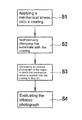
- a method according to an example embodiment of the present invention is shown in schematically simplified form in the drawing in the form of a block diagram, and is explained in more detail in the following description.
- FIGURE of the drawing shows a highly abbreviated flow diagram of the method according to an example embodiment of the present invention.
- a mechanical stress is applied onto a coating. Due to the mechanical stress, a substrate on which the coating is applied may become at least partly exposed due to detachment of the coating. However, it is also possible that, under defined conditions under which the stress is applied, no damage to the coating takes place. This is possible for example given high-quality lacquers.
- a coating is for example a color-imparting lacquer or a clear lacquer that is applied onto the substrate.
- the coating may also be a plastic layer, a ceramic layer, or a powdered coating that is applied to the substrate.
- the coating it is also possible for the coating to be a film glued onto the square.
- the coating may also be a vapor-deposited or electrochemically deposited layer, if the infrared emission differs from that of the substrate.
- Such a layer is for example a phosphating, as is carried out for example in order to provide rust protection on metallic surfaces, or is a metallic coating on a substrate made of plastic.
- the substrate is preferably a plate.
- the material of the substrate is for example a metal, a plastic, glass, or ceramic. There is no limitation of the materials for the substrate. Care must merely be taken that the emission properties for infrared light of the coating and of the substrate are different.
- a second step S 2 the substrate is isothermally clamped with the coating fashioned thereon.
- the isothermal clamping prevents different areas of the substrate with the coating fashioned thereon that have different temperatures from differently emitting the infrared radiation, thus causing errors in the image evaluation.
- isothermal clamping is understood to mean that the mount for the clamping, the substrate and the coating, and the surrounding air all have essentially the same temperature.
- “essentially the same temperature” means that the temperature difference is not greater than 1 K.
- steps S 1 and S 2 that is, to first clamp the substrate with the coating, and then to apply the mechanical stress onto the coating.
- a third step S 3 an infrared photograph is made of the region in which the mechanical stress is applied onto the coating in step S 1 . Due to the different degrees of emission of infrared radiation of different materials, from the infrared photograph the regions can be recognized in which there is no longer any coating material on the substrate.
- the infrared radiation emission properties of a material differ as a function of temperature, it is necessary for the infrared photograph in step S 3 to be made under isothermal conditions. Otherwise, given temperature differences in the coating or in the substrate it would be possible for warmer or colder regions to be interpreted as regions in which there was no longer any coating on the substrate, although the coating was in fact in order in this area. On the other hand, it would of course also be possible for the region having a different temperature in the infrared photograph to create the impression that the coating is in order at this location, although in fact there was no longer any coating on the substrate.
- the substrate In order to achieve isothermal conditions for the infrared photograph, it is for example possible before generating the infrared photograph to wait until temperature differences that may exist in the substrate or in the coating have equalized themselves. It is preferable for the substrate to have only a small thickness, because in this case a homogenous temperature distribution arises more rapidly in the substrate.
- the substrate with the coating In order to prevent temperature differences from being applied by the handling of the substrate with the coating when applying the mechanical stress, it is preferable to first clamp the substrate with the coating and then to exert the mechanical stress on the substrate. This prevents, for example, the substrate from being heated due to being held by the tester at the points at which the tester contacts the substrate.
- the generation of the infrared photograph in step S 3 can take place simultaneously with the application of the mechanical stress in step S 1 , or may take place only after the application of the stress in step S 1 . In the example embodiment shown here, the generation of the infrared photograph does not take place until after the stress has been applied. This is possible if the application of the stress causes changes in the coating, but it is not necessary to determine the time at which the changes occur.
- the generation of the infrared photograph in step S 3 after the application of the mechanical stress is for example possible during the execution of a cross cutting in order to test the adhesion of the coating, a mandrel bending test in order to determine the bending elasticity, or a ball impact test in order to determine shock and impact elasticity.
- the substrate with the coating fashioned thereon is bent around a conical mandrel. Subsequently, the diameter is determined at which the coating shows cracks or flakes off.
- a ball is dropped onto the coating. The ball is dropped onto the coating from different heights until cracks or detachment phenomena first become visible in the coating. It is thus possible first to drop the ball and then to generate an infrared photograph, and to repeat this process until a crack or a detachment of the coating is visible in the infrared photograph.
- step S 3 In tests of the coating in which a continuously increasing stress is applied, in which the test is terminated as soon as cracks or detachment first appear in the coating, it is preferable that the infrared photograph be generated in step S 3 , while the application of the mechanical stress in step S 1 takes place simultaneously.
- a test is for example an Erichsen cupping test in order to test the bending elasticity of the coating.
- a ram is used to press a hardened polished steel ball, having a diameter of 20 mm, into the rear side of the substrate, fashioned as a test plate, with a constant advance speed of approximately 0.2 mm/sec until a first crack appears in the coating.
- the distance traveled by the plunger is read off as the cupping value. For this reason, it is important to recognize precisely the point in time at which the first crack appears in the coating. Therefore, it is necessary to generate infrared photographs at brief intervals of the area of the coating that is stressed by the Erichsen cupping test, while the test is being carried out. Particularly preferably, the infrared photographs are generated at intervals short enough that an infrared film is produced.
- this photograph is evaluated in step S 4 .
- the evaluation of the infrared photograph in step S 4 can be made optically by a tester or in automated fashion by an image processing system.
- the evaluation of the infrared photograph is carried out by an image processing system. The advantage of the image processing system is that the evaluation takes place objectively. Any subjective influence on the part of the tester is excluded.
- any image processing system known to those skilled in the art may be used. It is required only that the image processing system recognize color differences.
- the image evaluation of the infrared photograph can take place either as a color image, the photograph preferably being separated into the individual color channels, or the grayscale images are evaluated.
- the surfaces in which the coating is visible are compared to the surfaces in which the substrate is visible, i.e. the coating has flaked off.
- the portion of the surface in which the coating has flaked off is indicated in %.
Abstract
Description
-
- (a) Applying a mechanical stress on the coating,
- (b) Isothermal clamping of the substrate with the coating and generating an infrared photograph of the region in which the mechanical stress is applied onto the coating in step (a),
- (c) Evaluation of the infrared photograph.
Claims (12)
Applications Claiming Priority (4)
| Application Number | Priority Date | Filing Date | Title |
|---|---|---|---|
| DE102006051895.0 | 2006-10-31 | ||
| DE102006051895A DE102006051895A1 (en) | 2006-10-31 | 2006-10-31 | Method for evaluating mechanical tests of a coating |
| DE102006051895 | 2006-10-31 | ||
| PCT/EP2007/059520 WO2008052835A2 (en) | 2006-10-31 | 2007-09-11 | Method for evaluating mechanical test of a coating |
Publications (2)
| Publication Number | Publication Date |
|---|---|
| US20100149339A1 US20100149339A1 (en) | 2010-06-17 |
| US8717440B2 true US8717440B2 (en) | 2014-05-06 |
Family
ID=39273156
Family Applications (1)
| Application Number | Title | Priority Date | Filing Date |
|---|---|---|---|
| US12/447,975 Expired - Fee Related US8717440B2 (en) | 2006-10-31 | 2007-09-11 | Method for evaluating mechanical tests of a coating |
Country Status (4)
| Country | Link |
|---|---|
| US (1) | US8717440B2 (en) |
| EP (1) | EP2087345A2 (en) |
| DE (1) | DE102006051895A1 (en) |
| WO (1) | WO2008052835A2 (en) |
Families Citing this family (2)
| Publication number | Priority date | Publication date | Assignee | Title |
|---|---|---|---|---|
| US8751457B2 (en) * | 2012-01-01 | 2014-06-10 | Bank Of America Corporation | Mobile device data archiving |
| CN108072577A (en) * | 2018-02-08 | 2018-05-25 | 水利部产品质量标准研究所 | A kind of hot-spraying coating toughness detection device and test method |
Citations (5)
| Publication number | Priority date | Publication date | Assignee | Title |
|---|---|---|---|---|
| EP1450155A1 (en) | 2001-11-19 | 2004-08-25 | The Circle for the Promotion of Science and Engineering | Method for thermal analysis and system for thermal analysis |
| US20050186328A1 (en) * | 2004-02-05 | 2005-08-25 | Snecma Moteurs | Method of measuring the adhesion of a coating to a substrate |
| US20070044397A1 (en) * | 2005-08-09 | 2007-03-01 | Wiercinski Robert A | Skid resistant surfaces |
| US20110090332A1 (en) * | 2000-09-25 | 2011-04-21 | Sensovation Ag | Image sensor device, apparatus and method for optical measurement |
| US8182719B2 (en) * | 2003-06-11 | 2012-05-22 | Yeda Research And Development Company Ltd. | Pyroelectric compound and method of its preparation |
-
2006
- 2006-10-31 DE DE102006051895A patent/DE102006051895A1/en not_active Withdrawn
-
2007
- 2007-09-11 EP EP07820125A patent/EP2087345A2/en not_active Withdrawn
- 2007-09-11 US US12/447,975 patent/US8717440B2/en not_active Expired - Fee Related
- 2007-09-11 WO PCT/EP2007/059520 patent/WO2008052835A2/en active Application Filing
Patent Citations (5)
| Publication number | Priority date | Publication date | Assignee | Title |
|---|---|---|---|---|
| US20110090332A1 (en) * | 2000-09-25 | 2011-04-21 | Sensovation Ag | Image sensor device, apparatus and method for optical measurement |
| EP1450155A1 (en) | 2001-11-19 | 2004-08-25 | The Circle for the Promotion of Science and Engineering | Method for thermal analysis and system for thermal analysis |
| US8182719B2 (en) * | 2003-06-11 | 2012-05-22 | Yeda Research And Development Company Ltd. | Pyroelectric compound and method of its preparation |
| US20050186328A1 (en) * | 2004-02-05 | 2005-08-25 | Snecma Moteurs | Method of measuring the adhesion of a coating to a substrate |
| US20070044397A1 (en) * | 2005-08-09 | 2007-03-01 | Wiercinski Robert A | Skid resistant surfaces |
Non-Patent Citations (4)
| Title |
|---|
| Arruda, E.M., et al, "Effects of Strain Rate, Temperature and Thermomechanical Coupling on the Finite Strain Deformation of Glassy Polymers", Mechanics of Materials Netherlands, vol. 19, No. 2-3, Jan. 1995, pp. 193-212. |
| Honner, M., et al., "Thermography Analyses of the Hole-Drilling Residual Stress Measuring Technique", Infrared Physics and Technology Elsevier Netherlands, vol. 45, No. 2, Mar. 2004, pp. 131-142, XP00247619. |
| International Search Report, PCT/EP2007/059520, dated May 8, 2008. |
| Meola, C., et al. "Application if Infrared Thermography to Adhesion Science", Journal of Adhesion Science and Technology, Zeist, NL, vol. 20, No. 7, Jun. 2006, pp. 589-632. |
Also Published As
| Publication number | Publication date |
|---|---|
| DE102006051895A1 (en) | 2008-05-21 |
| EP2087345A2 (en) | 2009-08-12 |
| WO2008052835A3 (en) | 2008-06-19 |
| US20100149339A1 (en) | 2010-06-17 |
| WO2008052835A2 (en) | 2008-05-08 |
Similar Documents
| Publication | Publication Date | Title |
|---|---|---|
| US8717440B2 (en) | Method for evaluating mechanical tests of a coating | |
| US20050023468A1 (en) | Systems and methods for inspecting coatings | |
| KR20140031290A (en) | Method and device for determining the pressure distribution for bonding | |
| Duncan et al. | Characterising strength of adhesion. | |
| US8667844B1 (en) | Ultrasonic scalar adhesion test apparatus and method for paints and finishes | |
| US20040149026A1 (en) | Method and devices for quantitative evaluation of coatings | |
| US8723537B2 (en) | Probe inspecting method and curable resin composition | |
| CN108896331B (en) | Method for online detection of grease cleaning efficiency of cleaning equipment before coating | |
| KR101309046B1 (en) | Measuring method for interfacial adhesion strength of film | |
| Lonyuk et al. | Relation between chip resistance and mechanical properties of automotive coatings | |
| CN114216403B (en) | Discontinuous deformation measurement method based on infrared and visible light double-light camera | |
| Duncan et al. | Measurement Good Practice Guide No. 72 | |
| KR100949316B1 (en) | Standard Indentation Sample for Calibration of Vickers Hardness Indentation Measuring Instrument | |
| Forster et al. | A multilens measurement platform for high-throughput adhesion measurements | |
| US11780153B2 (en) | Wrapping | |
| DE102010023655A1 (en) | Method for performing non-destructive examination on planar workpieces using pulse thermography for detecting corrosion damages, involves recording intensity images using thermography camera | |
| CN111351788A (en) | Tear film damage detection device and detection method | |
| CN113015898A (en) | Method for detecting the adhesion properties of a layer, in particular a wear-resistant layer | |
| US7160479B2 (en) | Method and apparatus for evaluating panel drip tests | |
| Ringermacher et al. | Thermal Imaging NDT at General Electric | |
| Barbato et al. | Determination of micro-indentation hardness of organic coatings | |
| Pietschmann | Measurement and Test Engineering | |
| JP4305267B2 (en) | Thin film layer adhesion evaluation method | |
| Dinardo et al. | Automatic defect detection from thermographic non destructive testing | |
| JPH10332560A (en) | Device and method for evaluating thin-film adhesion strength |
Legal Events
| Date | Code | Title | Description |
|---|---|---|---|
| AS | Assignment |
Owner name: ROBERT BOSCH GMBH,GERMANY Free format text: ASSIGNMENT OF ASSIGNORS INTEREST;ASSIGNORS:WAGNER, EVA;BRINZ, THOMAS;GEIGER, THOMAS;AND OTHERS;SIGNING DATES FROM 20090616 TO 20090904;REEL/FRAME:023896/0178 Owner name: ROBERT BOSCH GMBH, GERMANY Free format text: ASSIGNMENT OF ASSIGNORS INTEREST;ASSIGNORS:WAGNER, EVA;BRINZ, THOMAS;GEIGER, THOMAS;AND OTHERS;SIGNING DATES FROM 20090616 TO 20090904;REEL/FRAME:023896/0178 |
|
| AS | Assignment |
Owner name: ROBERT BOSCH GMBH,GERMANY Free format text: CORRECTIVE ASSIGNMENT TO CORRECT THE INCORRECT SPELLING OF THE 7TH ASSIGNOR'S NAME TO READ --SEBASTIAN KOLTZENBURG-- PREVIOUSLY RECORDED ON REEL 023896 FRAME 0178. ASSIGNOR(S) HEREBY CONFIRMS THE EVA WAGNER, THOMAS BRINZ, THOMAS GEIGER, JANE LEWIS, MARKUS TIEFENBACHER, TOBIAS BURK, SEBASTIAN KOLTZENBURG AND WOLFGANG SCHROF;ASSIGNORS:WAGNER, EVA;BRINZ, THOMAS;GEIGER, THOMAS;AND OTHERS;SIGNING DATES FROM 20090616 TO 20090904;REEL/FRAME:024014/0631 Owner name: ROBERT BOSCH GMBH, GERMANY Free format text: CORRECTIVE ASSIGNMENT TO CORRECT THE INCORRECT SPELLING OF THE 7TH ASSIGNOR'S NAME TO READ --SEBASTIAN KOLTZENBURG-- PREVIOUSLY RECORDED ON REEL 023896 FRAME 0178. ASSIGNOR(S) HEREBY CONFIRMS THE EVA WAGNER, THOMAS BRINZ, THOMAS GEIGER, JANE LEWIS, MARKUS TIEFENBACHER, TOBIAS BURK, SEBASTIAN KOLTZENBURG AND WOLFGANG SCHROF;ASSIGNORS:WAGNER, EVA;BRINZ, THOMAS;GEIGER, THOMAS;AND OTHERS;SIGNING DATES FROM 20090616 TO 20090904;REEL/FRAME:024014/0631 |
|
| AS | Assignment |
Owner name: BASF AG, GERMANY Free format text: CORRECTIVE ASSIGNMENT TO CORRECT THE ASSIGNEE INFORMATION PREVIOUSLY RECORDED ON REEL 024014 FRAME 0631. ASSIGNOR(S) HEREBY CONFIRMS THE TWO ASSIGNEES ARE ROBERT BOSCH GMBH AND BASF AG;ASSIGNORS:WAGNER, EVA;BRINZ, THOMAS;GEIGER, THOMAS;AND OTHERS;SIGNING DATES FROM 20090616 TO 20090904;REEL/FRAME:032270/0971 Owner name: ROBERT BOSCH GMBH, GERMANY Free format text: CORRECTIVE ASSIGNMENT TO CORRECT THE ASSIGNEE INFORMATION PREVIOUSLY RECORDED ON REEL 024014 FRAME 0631. ASSIGNOR(S) HEREBY CONFIRMS THE TWO ASSIGNEES ARE ROBERT BOSCH GMBH AND BASF AG;ASSIGNORS:WAGNER, EVA;BRINZ, THOMAS;GEIGER, THOMAS;AND OTHERS;SIGNING DATES FROM 20090616 TO 20090904;REEL/FRAME:032270/0971 |
|
| CC | Certificate of correction | ||
| FEPP | Fee payment procedure |
Free format text: MAINTENANCE FEE REMINDER MAILED (ORIGINAL EVENT CODE: REM.) |
|
| LAPS | Lapse for failure to pay maintenance fees |
Free format text: PATENT EXPIRED FOR FAILURE TO PAY MAINTENANCE FEES (ORIGINAL EVENT CODE: EXP.) |
|
| STCH | Information on status: patent discontinuation |
Free format text: PATENT EXPIRED DUE TO NONPAYMENT OF MAINTENANCE FEES UNDER 37 CFR 1.362 |
|
| FP | Lapsed due to failure to pay maintenance fee |
Effective date: 20180506 |