US8714232B2 - Method of making a brake component - Google Patents
Method of making a brake component Download PDFInfo
- Publication number
- US8714232B2 US8714232B2 US12/885,813 US88581310A US8714232B2 US 8714232 B2 US8714232 B2 US 8714232B2 US 88581310 A US88581310 A US 88581310A US 8714232 B2 US8714232 B2 US 8714232B2
- Authority
- US
- United States
- Prior art keywords
- insert
- mold cavity
- spacers
- die member
- molten material
- Prior art date
- Legal status (The legal status is an assumption and is not a legal conclusion. Google has not performed a legal analysis and makes no representation as to the accuracy of the status listed.)
- Active, expires
Links
Images


Classifications
-
- B—PERFORMING OPERATIONS; TRANSPORTING
- B22—CASTING; POWDER METALLURGY
- B22D—CASTING OF METALS; CASTING OF OTHER SUBSTANCES BY THE SAME PROCESSES OR DEVICES
- B22D17/00—Pressure die casting or injection die casting, i.e. casting in which the metal is forced into a mould under high pressure
- B22D17/20—Accessories: Details
- B22D17/22—Dies; Die plates; Die supports; Cooling equipment for dies; Accessories for loosening and ejecting castings from dies
- B22D17/24—Accessories for locating and holding cores or inserts
-
- B—PERFORMING OPERATIONS; TRANSPORTING
- B22—CASTING; POWDER METALLURGY
- B22C—FOUNDRY MOULDING
- B22C21/00—Flasks; Accessories therefor
- B22C21/12—Accessories
- B22C21/14—Accessories for reinforcing or securing moulding materials or cores, e.g. gaggers, chaplets, pins, bars
-
- B—PERFORMING OPERATIONS; TRANSPORTING
- B22—CASTING; POWDER METALLURGY
- B22D—CASTING OF METALS; CASTING OF OTHER SUBSTANCES BY THE SAME PROCESSES OR DEVICES
- B22D19/00—Casting in, on, or around objects which form part of the product
Definitions
- the technical field of this disclosure generally relates to methods of making brake components for use in motor vehicle applications.
- Motor vehicle brake components are commonly subjected to vibrations during the course of normal operation. Among other potential adverse affects, these vibrations may result in noise that gets transmitted into the vehicle's passenger compartment and beyond. For example, while braking, the occurrence of both low and high frequency vibrations in one or more brake components oftentimes results in a particular noise that is heard and felt by a driver.
- friction damping a vehicle's brake components with a mechanism that utilizes friction to absorb and dissipate mechanical energy associated with the vibrations.
- a wide range of friction damping means have been developed for disposition into various parts of a brake component during the manufacturing stage. Such means ultimately contribute to friction damping by providing a surface that can frictionally interact with an adjacent contacting surface of the brake component.
- One embodiment may include a method that calls for supporting an insert in a mold cavity by way of one or more spacers and introducing a molten material into the mold cavity.
- the one or more spacers and the molten material may be of the same composition.
- Another embodiment may include a method that calls for providing a casting die having a mold cavity shaped for casting a brake component.
- the method may further include supporting at least one insert in the mold cavity with one or more spacers of a first composition.
- the method may additionally include casting a brake component in the mold cavity using a molten material of the first composition.
- Yet another embodiment may include a method that calls for providing a sand casting die having a mold cavity shaped for casting a brake component.
- the method may further include supporting at least one insert in a predetermined relationship to the mold cavity by way of one or more spacers comprising a first composition.
- the method may additionally include introducing a molten material comprising the first composition into the mold cavity.
- the method may also include gradually melting the one or more spacers in the molten material and solidifying the molten material around the insert and into a brake component of a uniform composition.
- FIG. 1 is a perspective view of a brake component in accordance with one embodiment of the invention
- FIG. 2 is a cross-sectional view of the brake component of FIG. 1 .
- FIG. 3 is a cross-sectional view of a casting die in an open position with at least one insert positioned in a mold cavity of the die according to one embodiment of the invention.
- FIG. 4 is a cross-sectional view of a casting die in a closed position after the introduction of a molten material into a mold cavity of the die.
- FIG. 5 is a cross-sectional view of a casting die in an open position with a brake component removed therefrom, according to one embodiment of the invention.
- FIG. 6 is a cross-sectional view of a casting die in an open position with at least one insert positioned in a mold cavity of the die according to one embodiment of the invention.
- FIGS. 1-5 show a brake component with a friction damping means disposed therein ( FIGS. 1-2 ) and a schematic illustration of a casting die for forming the brake component by casting ( FIGS. 3-5 ).
- a molten material that is to become the brake component may be introduced into a mold cavity of the casting die and around the friction damping means.
- the friction damping means may be supported in place by one or more spacers. Additionally, the one or more spacers may be of the same composition as the molten material.
- FIGS. 1-5 are directed towards a disc brake rotor 10 that includes an insert 16 for friction damping the rotor 10 .
- a disc brake rotor 10 is shown and described in the drawings, it should be understood that the methods described herein may be easily practiced in accordance with the forming of other brake components such as a brake drum or any other cast part.
- the disc brake rotor 10 for use in motor vehicle braking applications.
- the disc brake rotor 10 is mounted to the vehicle so that it can co-rotate in unison with a vehicle wheel (not shown).
- a driver of the vehicle can controllably stop or slow rotation of the wheel by initiating frictional contact between the disc brake rotor 10 and a brake element (not shown), usually by depressing a foot brake located underneath the steering column.
- the disc brake rotor 10 may be formed from any suitable material known to skilled artisans such as, but not limited to, cast iron, gray cast iron, titanium, aluminum, steel, stainless steel, a suitable alloy, or a metal matrix composite.
- the disc brake rotor 10 includes a rotor hat 12 and a rotor cheek 14 .
- the rotor hat 12 connects the rotor 10 to an axle hub (not shown) of a rotatable axle.
- the rotor hat 12 may be a centrally protruding portion of the disc brake rotor 10 and may include, among other features, an axle bore 18 and a plurality of bolt holes 20 .
- the axle bore 18 receives the axle therethrough so that the axle, the axle hub, and the rotor hat 12 may be fastened together by way of the plurality of bolt holes 20 , as is well known in the art.
- the rotor cheek 14 provides at least one interface for experiencing selective frictional contact with the braking element such as a brake pad carried on a brake caliper. As shown, the rotor cheek 14 extends radially from and annularly around the rotor hat 12 and includes a pair of oppositely facing braking surfaces 22 , 24 . Although not shown here, the rotor cheek 14 may include a web of ventilation vanes between the braking surfaces 22 , 24 for expelling heat from the rotor cheek 14 .
- the insert 16 friction damps the disc brake rotor 10 by frictionally interacting with a surface 26 of the rotor cheek 14 in response to vibrations imparted thereto.
- the insert 16 may be constructed to friction damp the disc brake rotor 10 in a number of fashions such as, for example, those described in U.S. patent application Ser. No. 11/780,828, which is commonly assigned to the assignee of this disclosure.
- the insert 16 may be disposed inside the rotor cheek 14 and at least partially encased therein.
- the insert 16 may further be a one-piece part that substantially coincides with the annular and radial dimensions of the rotor cheek 14 , as best shown in FIG. 2 .
- the insert 16 may be constructed from a variety of materials such as, but not limited to, a low carbon mild steel such as AISI 1010 steel and AISI 1008 steel, an aluminum-steel composite, cast iron, grey cast iron, a ferrous-manganese alloy, a metal matrix composites, ductile iron, and stainless steel. But the insert 16 , or inserts as the case may be, is not necessarily limited to the particular shapes, configurations, dimensions, or arrangement shown in the FIGS. 1 and 2 . To cite but one example, a plurality of arcuate inserts may be annularly aligned in an end-to-end relationship inside the rotor cheek 14 to closely resemble the one-piece insert 16 described above.
- the disc brake rotor 10 may also include multiple one-piece inserts that are axially spaced from one another when, for example, a web of ventilation vanes divides the rotor cheek 14 into two similar portions that each have an insert disposed therein.
- the disc brake rotor 10 may formed by casting. Casting, as used herein, includes introducing a molten or liquid material into a mold cavity and solidifying it therein.
- the molten or liquid material may be of any composition that, upon solidifying, renders the disc brake rotor 10 suitable for its intended use. Such compositions are generally known to skilled artisans and include those mentioned above.
- the casting of the disc brake rotor 10 may be accomplished by any type or style known to skilled artisans; the selection of which normally depends on various factors including, among others, the particular material to be cast and the size and complexity of the shape of the mold cavity.
- the casting of the disc brake rotor 10 may be part of a multi-stage manufacturing process in which the brake disc rotor 10 undergoes subsequent refinishing or machining, or it may be a stand-alone process in which the rotor 10 derived therefrom is a substantially finished product.
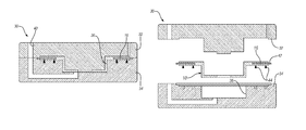
- An exemplary embodiment for casting the disc brake rotor 10 around the insert 16 will now be described with reference to FIGS. 3-5 .
- the sand casting die 30 may include an upper die member 32 and a lower die member 34 that, when closed, define a mold cavity 36 which represents the desired size and shape of the disc brake rotor 10 .
- Both the upper die member 32 and the lower die member 34 may be constructed from packed sand that is bonded together by clays, chemical binders, or oils, to name but a few.
- the sand casting die 30 may be oriented to accommodate horizontal casting. Or, if desired, vertical casting may be implemented. In any event, skilled artisans will know and understand the general construction and arrangement of the sand casting die 30 , as well as the many variations that can be employed, such that a more complete description need not be given here.
- the upper die member 32 and the lower die member 34 may be separated to make the mold cavity 36 accessible.
- the insert 16 may then be supported in the mold cavity by way of one or more spacers 38 , also commonly referred to as chaplets, which are shown here as being carried by the lower die member 34 .
- the one or more spacers 38 may be pre-arranged and imbedded in the lower die member 34 . Imbedding of the one or more spacers 38 can be accomplished during construction of the lower die member 34 by known techniques.
- the one or more spacers 38 may function to hold or support the insert 16 in place while maintaining a desirable spatial relationship and alignment with respect to the mold cavity 36 .
- the one or more spacers 38 may be carefully crafted to tight tolerances by casting or machining to help ensure the insert 16 is properly located as intended in the mold cavity 36 .
- the one or more spacers 38 may be crafted to support the insert 16 in the mold cavity 36 so that the insert 16 is approximately equidistant from the portions of the upper die member 32 and the lower die member 34 which define the rotor cheek 14 of the disc brake rotor 10 .
- the one or more spacers 38 may generally be in the shape of spikes, although such a construction is not necessary.
- the one or more spacers 38 may be of the same composition as the molten material that eventually solidifies to become the disc brake rotor 10 , which in this particular embodiment happens to be cast iron.
- the upper die member 32 and the lower die member 34 may be brought together to close the sand casting die 30 as shown in FIG. 4 .
- a charge of molten cast iron may be introduced into the mold cavity 36 through an inlet 40 . While the inlet 40 is shown here in the upper die mold 32 , skilled artisans will appreciate that the molten cast iron can be introduced into the mold cavity 36 in a multitude of fashions that are not shown or described in the drawings. Once introduced, the molten cast iron floods the mold cavity 36 and accumulates around any portion of the insert 16 and the one or more spacers 38 present therein.
- a surface coating composed of, but not limited to, a graphite-based material and/or a refractory-based material may be applied to the insert 16 to protect it from interacting with the molten cast iron in a manner that may adversely impact its friction damping characteristics.
- a coating material is IRONKOTE, which is available from Vesuvius Canada Refractories, Inc., of Welland, Ontario.
- IRONKOTE is composed of alumina particles (about 47.5%) and silicate particles (about 39.8%) dispersed in a lignosulfonate binder. While the thickness of the applied coating may vary depending on, among others, the compositional makeup of the coating and the environment to which the coating may be exposed, it usually ranges from is about 1 ⁇ m to about 500 ⁇ m.
- the molten cast iron introduced into the mold cavity 36 may be of the same composition as the one or more spacers 38 that support the insert 16 .
- the molten cast iron can gradually melt and ultimately consume the one or more spacers 38 without affecting its compositional integrity. That is, the one or more spacers 38 , upon melting, become indistinguishly intermixed or fused with the molten cast iron as it settles in the mold cavity 36 .
- the melting and consumption of the one or more spacers 38 has little effect on the spacing and alignment of the insert 16 with respect to the mold cavity 36 . This is because the one or more spacers 38 can substantially retain their structural rigidity and hence their load bearing capacity when the molten material is first introduced into the mold cavity 36 .
- the molten material will begin to settle and take shape in the mold cavity 36 around the insert 16 in a manner that more than adequately compensates for any loss of support due to the melting of the one or more spacers 38 .
- the molten cast iron is then allowed to solidify in the mold cavity 36 and around the insert 16 to form the disc brake rotor 10 .
- At least a portion of the one or more spacers 38 have now become part of the disc brake rotor 10 , more specifically the rotor cheek 14 as shown in the drawings, without promoting any significant compositional discontinuity therein. That is, the rotor cheek 14 of the disc brake rotor 10 exhibits a substantially uniform compositional profile that is free from regions or localized zones of significant compositional dissimilarities as a result of using the one or more spacers 38 in supporting the insert 16 . Such a characteristic may be helpful in improving the performance and preserving the disc brake rotor 10 when used in motor vehicle braking applications.
- some of the adverse affects relating to brake rotor 10 operation that can be reduced or altogether eliminated include those associated with differing frictional coefficients along the braking surfaces 22 , 24 of the rotor cheek 14 , the occurrence of localized corrosion, the presence of regions that experience different rates of thermal expansion, the possibility of accelerated wear of the rotor cheek 14 and the brake element, and noise generation.
- the disc brake rotor 10 with the insert 16 disposed therein may be removed from the mold cavity 36 , as illustratively shown in FIG. 5 .
- the upper die member 32 and the lower die member 34 may be separated to the extent possible since the die members 32 , 34 are constructed from packed sand. Any residual sand or chunks of sand may then be brushed or swept away to disencumber the brake disc rotor 10 .
- the brake disc rotor 10 may now undergo any subsequent refinishing or machining deemed necessary, such as cutting off an exposed portion 42 of the insert 16 to make if flush with the edge of the rotor cheek 12 and/or removing any imperfections, such as bulges or protrusions. Any remnants 44 attributable to the one or more spacers 38 may also be removed by known machining techniques or other appropriate procedures as well.
- FIG. 6 there is shown an alternative exemplary embodiment for sand casting the disc brake rotor 10 .
- This embodiment is similar in many respects to the embodiment shown in FIGS. 3-5 and, as such, those similarities will not be repeated here.
- At least one difference in this embodiment is the shape of the one or more spacers 138 for supporting the one or more inserts 16 in the mold cavity 36 of a sand casting die 30 .
- the one or more spacers 138 may be I-shaped.
- At least one other difference is that, after the sand casting die 30 is constructed, the one or more spacers 138 may be positioned in and around the mold cavity 36 in a random pattern or in conjunction with pre-formed indentations or locator marks. This technique may be useful if embedding the one or more spacers 138 in the sand casting die 30 is undesirable for whatever reason.
- other alternative exemplary embodiments for casting a brake component include the use of die casting.
- Die casting much like the various sand casting embodiments described above, is generally known and understood in the art and typically includes the use of an upper die member and a lower die member each constructed from a metal such as steel. Die casting may be utilized, for example, when a molten material used to cast the brake component is aluminum, zinc, or a related alloy.
- other alternative exemplary embodiments not particularly shown or described include those which substitute or combine subject matter from the various exemplary embodiments discussed above.
Landscapes
- Engineering & Computer Science (AREA)
- Mechanical Engineering (AREA)
- Braking Arrangements (AREA)
Abstract
Description
Claims (32)
Priority Applications (3)
| Application Number | Priority Date | Filing Date | Title |
|---|---|---|---|
| US12/885,813 US8714232B2 (en) | 2010-09-20 | 2010-09-20 | Method of making a brake component |
| DE102011112176A DE102011112176A1 (en) | 2010-09-20 | 2011-09-01 | Method for producing a brake component |
| CN201110279373.3A CN102407286B (en) | 2010-09-20 | 2011-09-20 | Manufacture the method for brake component |
Applications Claiming Priority (1)
| Application Number | Priority Date | Filing Date | Title |
|---|---|---|---|
| US12/885,813 US8714232B2 (en) | 2010-09-20 | 2010-09-20 | Method of making a brake component |
Publications (2)
| Publication Number | Publication Date |
|---|---|
| US20120067537A1 US20120067537A1 (en) | 2012-03-22 |
| US8714232B2 true US8714232B2 (en) | 2014-05-06 |
Family
ID=45769147
Family Applications (1)
| Application Number | Title | Priority Date | Filing Date |
|---|---|---|---|
| US12/885,813 Active 2030-12-22 US8714232B2 (en) | 2010-09-20 | 2010-09-20 | Method of making a brake component |
Country Status (3)
| Country | Link |
|---|---|
| US (1) | US8714232B2 (en) |
| CN (1) | CN102407286B (en) |
| DE (1) | DE102011112176A1 (en) |
Cited By (5)
| Publication number | Priority date | Publication date | Assignee | Title |
|---|---|---|---|---|
| US20130140116A1 (en) * | 2011-12-05 | 2013-06-06 | Hyundai Motor Company | Method for producing brake disc, mold for producing brake disc, and brake disc |
| US20140158457A1 (en) * | 2012-12-12 | 2014-06-12 | GM Global Technology Operations LLC | Coulomb frictional damping coated product |
| US20150141182A1 (en) * | 2012-04-24 | 2015-05-21 | Gkn Sinter Metals, Llc | Dampening assembly and related method of making same |
| USD823200S1 (en) * | 2016-06-10 | 2018-07-17 | Brake Parts Inc Llc | Vehicle brake rotor |
| USD971978S1 (en) * | 2020-09-09 | 2022-12-06 | Harmonic Drive Systems Inc. | Speed reducer |
Families Citing this family (10)
| Publication number | Priority date | Publication date | Assignee | Title |
|---|---|---|---|---|
| US8968855B2 (en) | 2011-10-25 | 2015-03-03 | GM Global Technology Operations LLC | Method of forming a component having an insert |
| US9038271B2 (en) * | 2012-04-18 | 2015-05-26 | Xiaodi Huang | High thermal conductivity disk brakes |
| PL231589B1 (en) * | 2015-03-24 | 2019-03-29 | Thoni Alutec Spolka Z Ograniczona Odpowiedzialnoscia | Method for producing castings from light metal alloys with zonal reinforcements with metallic elements in the form of fusions, preferably in sand and permanent moulds |
| EP3397873B1 (en) | 2015-12-31 | 2022-09-07 | Intellectual Property Holdings, LLC | Method of making a metal matrix composite vented brake rotor |
| WO2017136810A1 (en) * | 2016-02-04 | 2017-08-10 | Intellectual Property Holdings, Llc | Device and method for forming a metal matrix composite vehicle component |
| CN106001413B (en) * | 2016-06-28 | 2018-02-27 | 湖北星源科技有限公司 | A kind of balance shaft support casting technique |
| CN105964918B (en) * | 2016-06-28 | 2018-03-02 | 湖北星源科技有限公司 | Lightweight balance shaft beam lost foam casting process method |
| WO2021237171A1 (en) * | 2020-05-22 | 2021-11-25 | Intellectual Property Holdings, Llc | Thermal management of metal matrix composite systems |
| DE102021208965A1 (en) * | 2021-08-16 | 2023-02-16 | HPL Technologies GmbH | Workpiece for coating with a finishing layer, and a calibration method for a workpiece |
| CN117182031A (en) * | 2023-07-14 | 2023-12-08 | 敏实汽车技术研发有限公司 | A die-casting molding method and die-casting parts |
Citations (135)
| Publication number | Priority date | Publication date | Assignee | Title |
|---|---|---|---|---|
| US974024A (en) | 1910-08-24 | 1910-10-25 | Charles B Carter | Metal-founding. |
| US1484421A (en) | 1924-02-19 | James s | ||
| US1989211A (en) | 1930-11-21 | 1935-01-29 | Bendix Brake Co | Composite brake drum |
| US2012838A (en) | 1933-10-17 | 1935-08-27 | Sydney G Tilden | Noise-dampener for brake drums |
| US2026878A (en) | 1932-06-14 | 1936-01-07 | Budd Wheel Co | Method of making brake drums |
| US2288438A (en) | 1940-08-08 | 1942-06-30 | Dach Max | Brake drum |
| US2603316A (en) | 1952-07-15 | Brake rotor | ||
| US2978793A (en) | 1958-04-16 | 1961-04-11 | Edward R Lamson | Method of lubricating anti-friction bearings |
| US3085391A (en) | 1960-10-13 | 1963-04-16 | S & M Products Company Inc | Automatic hydraulic transmission |
| US3127959A (en) | 1962-03-12 | 1964-04-07 | Wengrowski Bronislaus | Cooling device for brake drums and shoes |
| US3147828A (en) | 1961-08-17 | 1964-09-08 | Dayton Malleable Iron Co | Brake drum construction |
| US3292746A (en) | 1965-11-05 | 1966-12-20 | Kelsey Hayes Co | Vibration dampener for disk brakes |
| CH428319A (en) | 1965-09-08 | 1967-01-15 | Cav Ltd | Multi-cylinder internal combustion engine crankcases and process for their manufacture |
| US3378115A (en) | 1965-07-14 | 1968-04-16 | Gen Motors Corp | Disc damper |
| US3425523A (en) | 1967-06-12 | 1969-02-04 | Kelsey Hayes Co | Ventilated rotor with vibration dampener |
| US3475634A (en) | 1967-08-17 | 1969-10-28 | Alexandr Antonovich Bogdanov | Submergible oil-filled electric motor with a protecting unit for the drive of a submergible well pump |
| US3509973A (en) | 1967-04-28 | 1970-05-05 | Isuzu Motors Ltd | Anti-squeal disc braking device |
| US3575270A (en) | 1967-12-09 | 1971-04-20 | Jurid Werke Gmbh | Friction means |
| GB1230274A (en) | 1968-12-21 | 1971-04-28 | ||
| US3774472A (en) | 1972-10-02 | 1973-11-27 | Ammco Tools Inc | Vibration dampener |
| US3841448A (en) | 1973-06-14 | 1974-10-15 | Budd Co | Reinforced brake drum |
| DE2446938A1 (en) | 1974-09-28 | 1976-04-15 | Jurid Werke Gmbh | Noise damping device for device for disc brake - has cast in ring of granular material between friction faces |
| DE2458335A1 (en) | 1974-12-10 | 1976-06-16 | Promat | Ceramic fibre inserts in cast brake discs - used to alter resonant frequencies and reduce squealing of brakes |
| US3975894A (en) | 1972-12-28 | 1976-08-24 | Toyoda Automatic Loom Works, Ltd. | Vibration and sound dampening means |
| DE2537038A1 (en) | 1975-08-20 | 1977-03-03 | Engels Gmbh August | Noise damper for disc or drum brake - is solid or segmented graphite insert ring cast into disc |
| US4049085A (en) | 1976-08-10 | 1977-09-20 | Safety Racing Equipment, Incorporated | Caliper brake with assembly for rotor attachment to hub |
| US4072219A (en) | 1974-12-07 | 1978-02-07 | Itt Industries, Incorporated | Multi-part disc brake |
| US4195713A (en) | 1974-05-29 | 1980-04-01 | Reduc Acoustics Ab | Sandwich structures with partial damping layers |
| US4250950A (en) | 1978-11-03 | 1981-02-17 | Swiss Aluminium Ltd. | Mould with roughened surface for casting metals |
| US4278153A (en) | 1978-11-24 | 1981-07-14 | Goodyear Aerospace Corporation | Brake friction material with reinforcement material |
| US4338758A (en) | 1978-04-18 | 1982-07-13 | Reduc Acoustics Ab | Vibration damped structures and objects |
| US4379501A (en) | 1980-02-27 | 1983-04-12 | Nissan Motor Co., Ltd. | Ventilated disk brake |
| US4523666A (en) | 1983-08-03 | 1985-06-18 | Motor Wheel Corporation | Brake rotor with vibration harmonic suppression, and method of manufacture |
| US4529079A (en) | 1980-01-16 | 1985-07-16 | Borg-Warner Corporation | Cushion-bonded driven disc assembly and method of construction |
| EP0205713A1 (en) | 1985-06-10 | 1986-12-30 | Motor Wheel Corporation | Brake rotor with vibration harmonic suppression |
| US5004078A (en) | 1988-11-09 | 1991-04-02 | Aisin Takaoka Co., Ltd. | Ventilated disk and process for making same |
| US5025547A (en) | 1990-05-07 | 1991-06-25 | Aluminum Company Of America | Method of providing textures on material by rolling |
| US5083643A (en) | 1989-10-10 | 1992-01-28 | Abex Corporation | Noise abating brake shoe |
| US5115891A (en) | 1990-12-17 | 1992-05-26 | The Budd Company | Composite brake drum with improved locating means for reinforcement assembly |
| US5139117A (en) | 1990-08-27 | 1992-08-18 | General Motors Corporation | Damped disc brake rotor |
| US5143184A (en) | 1991-02-14 | 1992-09-01 | Allied-Signal Inc. | Carbon composite brake disc with positive vibration damping |
| US5184663A (en) | 1988-06-14 | 1993-02-09 | Aisin Takaoka Co., Ltd. | Ventilated disk and process for making same |
| US5259486A (en) | 1992-02-12 | 1993-11-09 | The Budd Company | Integral casted labrynth ring for brake drum |
| US5310025A (en) | 1992-07-23 | 1994-05-10 | Allied-Signal Inc. | Aircraft brake vibration damper |
| US5416962A (en) | 1993-12-08 | 1995-05-23 | Eagle-Picher Industries, Inc. | Method of manufacture of vibration damper |
| US5417313A (en) | 1991-07-23 | 1995-05-23 | Akebno Brake Industry Co., Ltd. | Disc rotor for preventing squeal |
| US5509510A (en) | 1993-06-30 | 1996-04-23 | Kelsey-Hayes Company | Composite disc brake rotor and method for producing same |
| US5539213A (en) | 1995-01-27 | 1996-07-23 | International Business Machines Corporation | Process and apparatus for laser analysis of surface having a repetitive texture pattern |
| US5582231A (en) | 1995-04-28 | 1996-12-10 | General Motors Corporation | Sand mold member and method |
| US5620042A (en) | 1993-06-30 | 1997-04-15 | Kelsey-Hayes Company | Method of casting a composite disc brake rotor |
| US5660251A (en) | 1995-05-26 | 1997-08-26 | Sumitomo Electric Industries, Ltd. | Vibration damping device for disc brake |
| DE19649919A1 (en) | 1996-12-02 | 1998-06-04 | Actech Gmbh Adv Casting Tech | Brake members made of composite casting, namely brake drum, brake disc or the like, and composite casting method for the production of brake members |
| WO1998023877A1 (en) | 1996-11-27 | 1998-06-04 | Alliedsignal Inc. | Multi-disk brake actuator for vibration damping |
| US5789066A (en) | 1994-09-16 | 1998-08-04 | Sidmar N.V. | Method and device for manufacturing cold rolled metal sheets or strips and metal sheets or strips obtained |
| US5819882A (en) | 1996-04-02 | 1998-10-13 | Alliedsignal Inc. | Multi-disc brake actuator for vibration damping |
| US5855257A (en) | 1996-12-09 | 1999-01-05 | Chrysler Corporation | Damper for brake noise reduction |
| US5862892A (en) | 1996-04-16 | 1999-01-26 | Hayes Lemmerz International Inc. | Composite rotor for caliper disc brakes |
| US5878843A (en) | 1997-09-24 | 1999-03-09 | Hayes Lemmerz International, Inc. | Laminated brake rotor |
| GB2328952A (en) | 1997-09-09 | 1999-03-10 | T & N Technology Ltd | Grey cast iron disc brake rotor |
| US5927447A (en) | 1997-06-27 | 1999-07-27 | Hayes Lemmerz International, Inc. | Composite brake drum |
| US5965249A (en) | 1997-08-07 | 1999-10-12 | Gore Enterprise Holdings, Inc. | Vibration damping composite material |
| US6047794A (en) | 1996-12-19 | 2000-04-11 | Sumitomo Electric Industries, Ltd. | Vibration damper for use in wheel brake |
| US6073735A (en) | 1998-02-02 | 2000-06-13 | Aluminium Rheinfelden Gmbh | Brake disc |
| US6112865A (en) | 1996-12-09 | 2000-09-05 | Chrysler Corporation | Damper for brake noise reduction (brake drums) |
| DE19948009C1 (en) | 1999-10-06 | 2001-03-01 | Continental Teves Ag & Co Ohg | Brake disc for automobile disc brakes has 2 friction ring discs attached to disc head with ventilation channels between radial struts of friction disc rings provided with radial rupture points |
| US6206150B1 (en) | 1998-12-29 | 2001-03-27 | Hayes Lemmerz International Inc. | Composite brake drum having a balancing skirt |
| US6216827B1 (en) | 1996-07-24 | 2001-04-17 | Toyota Jidosha Kabushiki Kaisha | Disc brake rotor which generates vibration having a large component in a direction of a rotational axis of the disc brake rotor |
| US6223866B1 (en) | 2000-06-30 | 2001-05-01 | Kelsey-Hayes Company | Damped pad spring for use in a disc brake assembly |
| US6231456B1 (en) | 1999-04-05 | 2001-05-15 | Graham Rennie | Golf shaft vibration damper |
| WO2001036836A1 (en) | 1999-11-15 | 2001-05-25 | Newtech Brake Corporation Inc. | Rotor disk assembly for full contact brake |
| US6241056B1 (en) | 1998-12-29 | 2001-06-05 | Hayes Lemmerz International, Inc. | Composite brake drum |
| US6241055B1 (en) | 1998-09-11 | 2001-06-05 | Hayes Lemmerz International, Inc. | Rotor with viscoelastic vibration reducing element and method of making the same |
| KR20010049837A (en) | 1999-09-02 | 2001-06-15 | 토마스 더블유. 버크맨 | Air damper with graphite coated lip seal |
| US6283258B1 (en) | 2000-08-29 | 2001-09-04 | Ford Global Technologies, Inc. | Brake assembly with noise damping |
| US6302246B1 (en) | 1998-12-23 | 2001-10-16 | Daimlerchrysler Ag | Brake unit |
| US6357557B1 (en) | 2000-12-20 | 2002-03-19 | Kelsey-Hayes Company | Vehicle wheel hub and brake rotor and method for producing same |
| DE60000008T2 (en) | 2000-03-09 | 2002-03-28 | Freni Brembo S.P.A., Curno | Vented disc for disc brake |
| US6405839B1 (en) | 2001-01-03 | 2002-06-18 | Delphi Technologies, Inc. | Disc brake rotor |
| US20020104721A1 (en) | 2000-09-14 | 2002-08-08 | Marion Schaus | Disc brakes |
| US6465110B1 (en) | 2000-10-10 | 2002-10-15 | Material Sciences Corporation | Metal felt laminate structures |
| US6481545B1 (en) | 2001-03-30 | 2002-11-19 | Nichias Corporation | Vibration damping shim structure |
| US6505716B1 (en) | 1999-11-05 | 2003-01-14 | Hayes Lemmerz International, Inc. | Damped disc brake rotor |
| US6507716B2 (en) | 2000-05-30 | 2003-01-14 | Sharp Kabushiki Kaisha | Image forming apparatus having user and stored job indentification and association capability, a stored job content display and multiple job type image forming control displays |
| US20030037999A1 (en) | 2001-08-23 | 2003-02-27 | Toshio Tanaka | Vibration inhibiting structure for rotor |
| DE10141698A1 (en) | 2001-08-25 | 2003-03-06 | Bosch Gmbh Robert | Vibration-damped component of a motor vehicle |
| US6543518B1 (en) | 1999-10-25 | 2003-04-08 | Tooling & Equipment International | Apparatus and method for casting |
| US20030127297A1 (en) | 2002-01-09 | 2003-07-10 | Smith Anthony L. | Magnetorheological fluid fan drive design for manufacturability |
| JP2003214465A (en) | 2002-01-22 | 2003-07-30 | Koyo Seiko Co Ltd | Disc rotor for brake and bearing device |
| US20030141154A1 (en) | 2000-05-08 | 2003-07-31 | Yvon Rancourt | Rotor for disk brake assembly |
| US6648055B1 (en) | 1999-04-16 | 2003-11-18 | Daimlerchrysler Ag | Casting tool and method of producing a component |
| US20030213658A1 (en) | 2002-05-16 | 2003-11-20 | Advics Co., Ltd. | Disc brake |
| JP2004011841A (en) | 2002-06-10 | 2004-01-15 | Kawasaki Heavy Ind Ltd | brake disc |
| US20040031581A1 (en) | 2002-03-18 | 2004-02-19 | Herreid Richard M. | Method and apparatus for making a sand core with an improved production rate |
| US20040045692A1 (en) | 2002-09-10 | 2004-03-11 | Redemske John A | Method of heating casting mold |
| US20040074712A1 (en) | 2002-10-22 | 2004-04-22 | Ford Global Technologies, Inc. | Brake assembly with tuned mass damper |
| US20040084260A1 (en) | 2002-11-01 | 2004-05-06 | J. L. French Automotive Castings, Inc. | Integrated brake rotor |
| US6799664B1 (en) | 2002-03-29 | 2004-10-05 | Kelsey-Hayes Company | Drum brake assembly |
| US20040242363A1 (en) | 2003-05-30 | 2004-12-02 | Toyota Jidosha Kabushiki Kaisha | Rotating shaft support apparatus and differential gear unit |
| US20050011628A1 (en) | 2003-07-18 | 2005-01-20 | John Frait | Method and apparatus for forming a part with dampener |
| US6880681B2 (en) | 2000-05-29 | 2005-04-19 | Honda Giken Kogyo Kabushiki Kaisha | Brake drum and method for producing the same |
| US6890218B2 (en) | 2001-11-05 | 2005-05-10 | Ballard Power Systems Corporation | Three-phase connector for electric vehicle drivetrain |
| US6899158B2 (en) | 2002-09-04 | 2005-05-31 | Kioritz Corporation | Insert core and method for manufacturing a cylinder for internal combustion engine by making use of the insert core |
| US20050150222A1 (en) | 2003-12-30 | 2005-07-14 | Kalish Martin W. | One piece catalytic converter with integral exhaust manifold |
| US6932917B2 (en) | 2001-08-06 | 2005-08-23 | General Motors Corporation | Magnetorheological fluids |
| US20050183909A1 (en) | 2004-01-21 | 2005-08-25 | Rau Charles B.Iii | Disc brake rotor assembly and method for producing same |
| US20050193976A1 (en) | 2004-03-04 | 2005-09-08 | Kozo Suzuki | Swirl forming device in combustion engine |
| CN1757948A (en) | 2004-10-08 | 2006-04-12 | 通用汽车公司 | Coulomb friction damped disc brake rotors |
| US7066235B2 (en) | 2002-05-07 | 2006-06-27 | Nanometal, Llc | Method for manufacturing clad components |
| US7112749B2 (en) | 2004-06-23 | 2006-09-26 | Sensata Technologies, Inc. | Sensor mounting apparatus for minimizing parasitic stress |
| US20060243547A1 (en) | 2005-04-04 | 2006-11-02 | Holger Keller | Brake disc, particularly an internally ventilated brake disc |
| DE60116780T2 (en) | 2001-07-27 | 2006-11-02 | Freni Brembo S.P.A. | METHOD FOR PRODUCING A BRAKE PULLEY OF A BRAKE DISC WITH VENTILATION CHANNELS AND MANUFACTURED BRAKE RING |
| CN2863313Y (en) | 2006-01-25 | 2007-01-31 | 秦经世 | Positioning device for cooling ring for piston |
| US7178795B2 (en) | 2003-12-23 | 2007-02-20 | Basf Corporation | Mounting assembly for a vehicle suspension component |
| US20070039710A1 (en) | 2005-08-19 | 2007-02-22 | Newcomb Thomas P | Foundry mold assembly device and method |
| US20070056815A1 (en) | 2005-09-15 | 2007-03-15 | Hanna Michael D | Bi-metal disc brake rotor and method of manufacturing |
| US20070062768A1 (en) | 2005-09-19 | 2007-03-22 | Hanna Michael D | Bi-metal disc brake rotor and method of manufacturing |
| US20070062664A1 (en) | 2005-09-20 | 2007-03-22 | Schroth James G | Method of casting components with inserts for noise reduction |
| DE102005051092B3 (en) | 2005-10-25 | 2007-03-29 | Daimlerchrysler Ag | Disk brake with composite cast iron disk support (sic), friction disks, brake disk casing, where friction disks are made from metallic friction material of higher corrosion resistance than cast iron disks integrally between friction disks |
| US20070142149A1 (en) | 2005-11-23 | 2007-06-21 | Kleber Richard M | Pulley assembly and method |
| US20070166425A1 (en) | 2006-01-17 | 2007-07-19 | Utsugi Masanori | Optical Element Molding Device |
| US20070235270A1 (en) | 2006-04-11 | 2007-10-11 | Thyssenkrupp-Waupaca Division | Insert for manufacture of an enhanced sound dampening composite rotor casting and method thereof |
| US7293755B2 (en) | 2004-11-04 | 2007-11-13 | Honda Motor Co., Ltd. | Vibration isolation device |
| US20070298275A1 (en) | 2006-06-27 | 2007-12-27 | Gm Global Technology Operations, Inc. | Damped automotive components with cast in place inserts and method of making same |
| DE102006034341A1 (en) | 2006-07-23 | 2008-01-31 | Fritz Winter Eisengiesserei Gmbh & Co. Kg | Method for producing a cast component with a cast-in pipe |
| US20080099289A1 (en) | 2006-10-30 | 2008-05-01 | Gm Global Technology Operations, Inc. | Coulomb damped disc brake rotor and method of manufacturing |
| US20080185249A1 (en) | 2004-10-08 | 2008-08-07 | Gm Global Technology Operations, Inc. | Damped products and methods of making and using the same |
| US20090032569A1 (en) | 2007-08-01 | 2009-02-05 | Gm Global Technology Operations, Inc. | Friction welding method and products made using the same |
| US20090078515A1 (en) * | 2007-09-20 | 2009-03-26 | Gm Global Technology Operations, Inc. | Lightweight brake rotor and components with composite materials |
| US20090078520A1 (en) * | 2007-09-24 | 2009-03-26 | Gm Global Technology Operations, Inc. | Insert with tabs and damped products and methods of making the same |
| US20090107787A1 (en) | 2007-10-29 | 2009-04-30 | Gm Global Technology Operations, Inc. | Inserts with holes for damped products and methods of making and using the same |
| DE102008037635A1 (en) | 2007-08-17 | 2009-05-14 | GM Global Technology Operations, Inc., Detroit | Cast noise dampened, vented brake discs with embedded inserts |
| US20090176122A1 (en) | 2008-01-04 | 2009-07-09 | Gm Global Technology Operations, Inc. | Method of forming casting with frictional damping insert |
| US7594568B2 (en) | 2005-11-30 | 2009-09-29 | Gm Global Technology Operations, Inc. | Rotor assembly and method |
| US7604098B2 (en) | 2005-08-01 | 2009-10-20 | Gm Global Technology Operations, Inc. | Coulomb friction damped disc brake caliper bracket |
| US7938378B2 (en) | 2007-08-01 | 2011-05-10 | GM Global Technology Operations LLC | Damped product with insert and method of making the same |
-
2010
- 2010-09-20 US US12/885,813 patent/US8714232B2/en active Active
-
2011
- 2011-09-01 DE DE102011112176A patent/DE102011112176A1/en not_active Ceased
- 2011-09-20 CN CN201110279373.3A patent/CN102407286B/en not_active Expired - Fee Related
Patent Citations (146)
| Publication number | Priority date | Publication date | Assignee | Title |
|---|---|---|---|---|
| US2603316A (en) | 1952-07-15 | Brake rotor | ||
| US1484421A (en) | 1924-02-19 | James s | ||
| US974024A (en) | 1910-08-24 | 1910-10-25 | Charles B Carter | Metal-founding. |
| US1989211A (en) | 1930-11-21 | 1935-01-29 | Bendix Brake Co | Composite brake drum |
| US2026878A (en) | 1932-06-14 | 1936-01-07 | Budd Wheel Co | Method of making brake drums |
| US2012838A (en) | 1933-10-17 | 1935-08-27 | Sydney G Tilden | Noise-dampener for brake drums |
| US2288438A (en) | 1940-08-08 | 1942-06-30 | Dach Max | Brake drum |
| US2978793A (en) | 1958-04-16 | 1961-04-11 | Edward R Lamson | Method of lubricating anti-friction bearings |
| US3085391A (en) | 1960-10-13 | 1963-04-16 | S & M Products Company Inc | Automatic hydraulic transmission |
| US3147828A (en) | 1961-08-17 | 1964-09-08 | Dayton Malleable Iron Co | Brake drum construction |
| US3127959A (en) | 1962-03-12 | 1964-04-07 | Wengrowski Bronislaus | Cooling device for brake drums and shoes |
| US3378115A (en) | 1965-07-14 | 1968-04-16 | Gen Motors Corp | Disc damper |
| CH428319A (en) | 1965-09-08 | 1967-01-15 | Cav Ltd | Multi-cylinder internal combustion engine crankcases and process for their manufacture |
| US3292746A (en) | 1965-11-05 | 1966-12-20 | Kelsey Hayes Co | Vibration dampener for disk brakes |
| US3509973A (en) | 1967-04-28 | 1970-05-05 | Isuzu Motors Ltd | Anti-squeal disc braking device |
| US3425523A (en) | 1967-06-12 | 1969-02-04 | Kelsey Hayes Co | Ventilated rotor with vibration dampener |
| US3475634A (en) | 1967-08-17 | 1969-10-28 | Alexandr Antonovich Bogdanov | Submergible oil-filled electric motor with a protecting unit for the drive of a submergible well pump |
| US3575270A (en) | 1967-12-09 | 1971-04-20 | Jurid Werke Gmbh | Friction means |
| GB1230274A (en) | 1968-12-21 | 1971-04-28 | ||
| US3774472A (en) | 1972-10-02 | 1973-11-27 | Ammco Tools Inc | Vibration dampener |
| US3975894A (en) | 1972-12-28 | 1976-08-24 | Toyoda Automatic Loom Works, Ltd. | Vibration and sound dampening means |
| US3841448A (en) | 1973-06-14 | 1974-10-15 | Budd Co | Reinforced brake drum |
| US4195713A (en) | 1974-05-29 | 1980-04-01 | Reduc Acoustics Ab | Sandwich structures with partial damping layers |
| DE2446938A1 (en) | 1974-09-28 | 1976-04-15 | Jurid Werke Gmbh | Noise damping device for device for disc brake - has cast in ring of granular material between friction faces |
| US4072219A (en) | 1974-12-07 | 1978-02-07 | Itt Industries, Incorporated | Multi-part disc brake |
| DE2458335A1 (en) | 1974-12-10 | 1976-06-16 | Promat | Ceramic fibre inserts in cast brake discs - used to alter resonant frequencies and reduce squealing of brakes |
| DE2537038A1 (en) | 1975-08-20 | 1977-03-03 | Engels Gmbh August | Noise damper for disc or drum brake - is solid or segmented graphite insert ring cast into disc |
| US4049085A (en) | 1976-08-10 | 1977-09-20 | Safety Racing Equipment, Incorporated | Caliper brake with assembly for rotor attachment to hub |
| US4338758A (en) | 1978-04-18 | 1982-07-13 | Reduc Acoustics Ab | Vibration damped structures and objects |
| US4250950A (en) | 1978-11-03 | 1981-02-17 | Swiss Aluminium Ltd. | Mould with roughened surface for casting metals |
| US4278153A (en) | 1978-11-24 | 1981-07-14 | Goodyear Aerospace Corporation | Brake friction material with reinforcement material |
| US4529079A (en) | 1980-01-16 | 1985-07-16 | Borg-Warner Corporation | Cushion-bonded driven disc assembly and method of construction |
| US4379501A (en) | 1980-02-27 | 1983-04-12 | Nissan Motor Co., Ltd. | Ventilated disk brake |
| US4523666A (en) | 1983-08-03 | 1985-06-18 | Motor Wheel Corporation | Brake rotor with vibration harmonic suppression, and method of manufacture |
| EP0205713A1 (en) | 1985-06-10 | 1986-12-30 | Motor Wheel Corporation | Brake rotor with vibration harmonic suppression |
| US5184663A (en) | 1988-06-14 | 1993-02-09 | Aisin Takaoka Co., Ltd. | Ventilated disk and process for making same |
| US5004078A (en) | 1988-11-09 | 1991-04-02 | Aisin Takaoka Co., Ltd. | Ventilated disk and process for making same |
| US5083643A (en) | 1989-10-10 | 1992-01-28 | Abex Corporation | Noise abating brake shoe |
| US5025547A (en) | 1990-05-07 | 1991-06-25 | Aluminum Company Of America | Method of providing textures on material by rolling |
| US5139117A (en) | 1990-08-27 | 1992-08-18 | General Motors Corporation | Damped disc brake rotor |
| US5115891A (en) | 1990-12-17 | 1992-05-26 | The Budd Company | Composite brake drum with improved locating means for reinforcement assembly |
| US5143184A (en) | 1991-02-14 | 1992-09-01 | Allied-Signal Inc. | Carbon composite brake disc with positive vibration damping |
| US5417313A (en) | 1991-07-23 | 1995-05-23 | Akebno Brake Industry Co., Ltd. | Disc rotor for preventing squeal |
| US5259486A (en) | 1992-02-12 | 1993-11-09 | The Budd Company | Integral casted labrynth ring for brake drum |
| US5310025A (en) | 1992-07-23 | 1994-05-10 | Allied-Signal Inc. | Aircraft brake vibration damper |
| US5509510A (en) | 1993-06-30 | 1996-04-23 | Kelsey-Hayes Company | Composite disc brake rotor and method for producing same |
| US5620042A (en) | 1993-06-30 | 1997-04-15 | Kelsey-Hayes Company | Method of casting a composite disc brake rotor |
| US5416962A (en) | 1993-12-08 | 1995-05-23 | Eagle-Picher Industries, Inc. | Method of manufacture of vibration damper |
| US5789066A (en) | 1994-09-16 | 1998-08-04 | Sidmar N.V. | Method and device for manufacturing cold rolled metal sheets or strips and metal sheets or strips obtained |
| US5539213A (en) | 1995-01-27 | 1996-07-23 | International Business Machines Corporation | Process and apparatus for laser analysis of surface having a repetitive texture pattern |
| US5582231A (en) | 1995-04-28 | 1996-12-10 | General Motors Corporation | Sand mold member and method |
| US5660251A (en) | 1995-05-26 | 1997-08-26 | Sumitomo Electric Industries, Ltd. | Vibration damping device for disc brake |
| US5819882A (en) | 1996-04-02 | 1998-10-13 | Alliedsignal Inc. | Multi-disc brake actuator for vibration damping |
| US5862892A (en) | 1996-04-16 | 1999-01-26 | Hayes Lemmerz International Inc. | Composite rotor for caliper disc brakes |
| US6216827B1 (en) | 1996-07-24 | 2001-04-17 | Toyota Jidosha Kabushiki Kaisha | Disc brake rotor which generates vibration having a large component in a direction of a rotational axis of the disc brake rotor |
| WO1998023877A1 (en) | 1996-11-27 | 1998-06-04 | Alliedsignal Inc. | Multi-disk brake actuator for vibration damping |
| DE19649919A1 (en) | 1996-12-02 | 1998-06-04 | Actech Gmbh Adv Casting Tech | Brake members made of composite casting, namely brake drum, brake disc or the like, and composite casting method for the production of brake members |
| US5855257A (en) | 1996-12-09 | 1999-01-05 | Chrysler Corporation | Damper for brake noise reduction |
| US6112865A (en) | 1996-12-09 | 2000-09-05 | Chrysler Corporation | Damper for brake noise reduction (brake drums) |
| US6047794A (en) | 1996-12-19 | 2000-04-11 | Sumitomo Electric Industries, Ltd. | Vibration damper for use in wheel brake |
| US5927447A (en) | 1997-06-27 | 1999-07-27 | Hayes Lemmerz International, Inc. | Composite brake drum |
| US5965249A (en) | 1997-08-07 | 1999-10-12 | Gore Enterprise Holdings, Inc. | Vibration damping composite material |
| GB2328952A (en) | 1997-09-09 | 1999-03-10 | T & N Technology Ltd | Grey cast iron disc brake rotor |
| US5878843A (en) | 1997-09-24 | 1999-03-09 | Hayes Lemmerz International, Inc. | Laminated brake rotor |
| US6073735A (en) | 1998-02-02 | 2000-06-13 | Aluminium Rheinfelden Gmbh | Brake disc |
| US6241055B1 (en) | 1998-09-11 | 2001-06-05 | Hayes Lemmerz International, Inc. | Rotor with viscoelastic vibration reducing element and method of making the same |
| US6302246B1 (en) | 1998-12-23 | 2001-10-16 | Daimlerchrysler Ag | Brake unit |
| US6206150B1 (en) | 1998-12-29 | 2001-03-27 | Hayes Lemmerz International Inc. | Composite brake drum having a balancing skirt |
| US6241056B1 (en) | 1998-12-29 | 2001-06-05 | Hayes Lemmerz International, Inc. | Composite brake drum |
| US6231456B1 (en) | 1999-04-05 | 2001-05-15 | Graham Rennie | Golf shaft vibration damper |
| US6648055B1 (en) | 1999-04-16 | 2003-11-18 | Daimlerchrysler Ag | Casting tool and method of producing a component |
| KR20010049837A (en) | 1999-09-02 | 2001-06-15 | 토마스 더블유. 버크맨 | Air damper with graphite coated lip seal |
| DE19948009C1 (en) | 1999-10-06 | 2001-03-01 | Continental Teves Ag & Co Ohg | Brake disc for automobile disc brakes has 2 friction ring discs attached to disc head with ventilation channels between radial struts of friction disc rings provided with radial rupture points |
| US6543518B1 (en) | 1999-10-25 | 2003-04-08 | Tooling & Equipment International | Apparatus and method for casting |
| US6505716B1 (en) | 1999-11-05 | 2003-01-14 | Hayes Lemmerz International, Inc. | Damped disc brake rotor |
| WO2001036836A1 (en) | 1999-11-15 | 2001-05-25 | Newtech Brake Corporation Inc. | Rotor disk assembly for full contact brake |
| DE60000008T2 (en) | 2000-03-09 | 2002-03-28 | Freni Brembo S.P.A., Curno | Vented disc for disc brake |
| US20030141154A1 (en) | 2000-05-08 | 2003-07-31 | Yvon Rancourt | Rotor for disk brake assembly |
| US6880681B2 (en) | 2000-05-29 | 2005-04-19 | Honda Giken Kogyo Kabushiki Kaisha | Brake drum and method for producing the same |
| US6507716B2 (en) | 2000-05-30 | 2003-01-14 | Sharp Kabushiki Kaisha | Image forming apparatus having user and stored job indentification and association capability, a stored job content display and multiple job type image forming control displays |
| US6223866B1 (en) | 2000-06-30 | 2001-05-01 | Kelsey-Hayes Company | Damped pad spring for use in a disc brake assembly |
| US6283258B1 (en) | 2000-08-29 | 2001-09-04 | Ford Global Technologies, Inc. | Brake assembly with noise damping |
| US20020104721A1 (en) | 2000-09-14 | 2002-08-08 | Marion Schaus | Disc brakes |
| US6465110B1 (en) | 2000-10-10 | 2002-10-15 | Material Sciences Corporation | Metal felt laminate structures |
| US6357557B1 (en) | 2000-12-20 | 2002-03-19 | Kelsey-Hayes Company | Vehicle wheel hub and brake rotor and method for producing same |
| US20020084156A1 (en) | 2001-01-03 | 2002-07-04 | Delphi Automotive Systems | Disc brake rotor |
| US6405839B1 (en) | 2001-01-03 | 2002-06-18 | Delphi Technologies, Inc. | Disc brake rotor |
| US6481545B1 (en) | 2001-03-30 | 2002-11-19 | Nichias Corporation | Vibration damping shim structure |
| DE60116780T2 (en) | 2001-07-27 | 2006-11-02 | Freni Brembo S.P.A. | METHOD FOR PRODUCING A BRAKE PULLEY OF A BRAKE DISC WITH VENTILATION CHANNELS AND MANUFACTURED BRAKE RING |
| US6932917B2 (en) | 2001-08-06 | 2005-08-23 | General Motors Corporation | Magnetorheological fluids |
| US20030037999A1 (en) | 2001-08-23 | 2003-02-27 | Toshio Tanaka | Vibration inhibiting structure for rotor |
| DE10141698A1 (en) | 2001-08-25 | 2003-03-06 | Bosch Gmbh Robert | Vibration-damped component of a motor vehicle |
| US6890218B2 (en) | 2001-11-05 | 2005-05-10 | Ballard Power Systems Corporation | Three-phase connector for electric vehicle drivetrain |
| US20030127297A1 (en) | 2002-01-09 | 2003-07-10 | Smith Anthony L. | Magnetorheological fluid fan drive design for manufacturability |
| JP2003214465A (en) | 2002-01-22 | 2003-07-30 | Koyo Seiko Co Ltd | Disc rotor for brake and bearing device |
| US20040031581A1 (en) | 2002-03-18 | 2004-02-19 | Herreid Richard M. | Method and apparatus for making a sand core with an improved production rate |
| US6799664B1 (en) | 2002-03-29 | 2004-10-05 | Kelsey-Hayes Company | Drum brake assembly |
| US7066235B2 (en) | 2002-05-07 | 2006-06-27 | Nanometal, Llc | Method for manufacturing clad components |
| US20030213658A1 (en) | 2002-05-16 | 2003-11-20 | Advics Co., Ltd. | Disc brake |
| JP2004011841A (en) | 2002-06-10 | 2004-01-15 | Kawasaki Heavy Ind Ltd | brake disc |
| US6899158B2 (en) | 2002-09-04 | 2005-05-31 | Kioritz Corporation | Insert core and method for manufacturing a cylinder for internal combustion engine by making use of the insert core |
| US20040045692A1 (en) | 2002-09-10 | 2004-03-11 | Redemske John A | Method of heating casting mold |
| US20040074712A1 (en) | 2002-10-22 | 2004-04-22 | Ford Global Technologies, Inc. | Brake assembly with tuned mass damper |
| US20040084260A1 (en) | 2002-11-01 | 2004-05-06 | J. L. French Automotive Castings, Inc. | Integrated brake rotor |
| US20040242363A1 (en) | 2003-05-30 | 2004-12-02 | Toyota Jidosha Kabushiki Kaisha | Rotating shaft support apparatus and differential gear unit |
| US20050011628A1 (en) | 2003-07-18 | 2005-01-20 | John Frait | Method and apparatus for forming a part with dampener |
| US6945309B2 (en) | 2003-07-18 | 2005-09-20 | Hayes Lemmerz International, Inc. | Method and apparatus for forming a part with dampener |
| US7178795B2 (en) | 2003-12-23 | 2007-02-20 | Basf Corporation | Mounting assembly for a vehicle suspension component |
| US20050150222A1 (en) | 2003-12-30 | 2005-07-14 | Kalish Martin W. | One piece catalytic converter with integral exhaust manifold |
| US20050183909A1 (en) | 2004-01-21 | 2005-08-25 | Rau Charles B.Iii | Disc brake rotor assembly and method for producing same |
| US20050193976A1 (en) | 2004-03-04 | 2005-09-08 | Kozo Suzuki | Swirl forming device in combustion engine |
| US7112749B2 (en) | 2004-06-23 | 2006-09-26 | Sensata Technologies, Inc. | Sensor mounting apparatus for minimizing parasitic stress |
| CN1757948A (en) | 2004-10-08 | 2006-04-12 | 通用汽车公司 | Coulomb friction damped disc brake rotors |
| DE102005048258A1 (en) | 2004-10-08 | 2006-04-27 | General Motors Corp., Detroit | Coulomb friction damped brake discs |
| US20060076200A1 (en) | 2004-10-08 | 2006-04-13 | Dessouki Omar S | Coulomb friction damped disc brake rotors |
| US20080185249A1 (en) | 2004-10-08 | 2008-08-07 | Gm Global Technology Operations, Inc. | Damped products and methods of making and using the same |
| US7293755B2 (en) | 2004-11-04 | 2007-11-13 | Honda Motor Co., Ltd. | Vibration isolation device |
| US20060243547A1 (en) | 2005-04-04 | 2006-11-02 | Holger Keller | Brake disc, particularly an internally ventilated brake disc |
| US7604098B2 (en) | 2005-08-01 | 2009-10-20 | Gm Global Technology Operations, Inc. | Coulomb friction damped disc brake caliper bracket |
| US20070039710A1 (en) | 2005-08-19 | 2007-02-22 | Newcomb Thomas P | Foundry mold assembly device and method |
| US7775332B2 (en) | 2005-09-15 | 2010-08-17 | Gm Global Technology Operations, Inc. | Bi-metal disc brake rotor and method of manufacturing |
| US20070056815A1 (en) | 2005-09-15 | 2007-03-15 | Hanna Michael D | Bi-metal disc brake rotor and method of manufacturing |
| US20070062768A1 (en) | 2005-09-19 | 2007-03-22 | Hanna Michael D | Bi-metal disc brake rotor and method of manufacturing |
| US7937819B2 (en) | 2005-09-19 | 2011-05-10 | GM Global Technology Operations LLC | Method of manufacturing a friction damped disc brake rotor |
| US7644750B2 (en) | 2005-09-20 | 2010-01-12 | Gm Global Technology Operations, Inc. | Method of casting components with inserts for noise reduction |
| WO2007035206A2 (en) | 2005-09-20 | 2007-03-29 | Gm Global Technology Operations, Inc. | Method of casting components with inserts for noise reduction |
| US20070062664A1 (en) | 2005-09-20 | 2007-03-22 | Schroth James G | Method of casting components with inserts for noise reduction |
| DE102005051092B3 (en) | 2005-10-25 | 2007-03-29 | Daimlerchrysler Ag | Disk brake with composite cast iron disk support (sic), friction disks, brake disk casing, where friction disks are made from metallic friction material of higher corrosion resistance than cast iron disks integrally between friction disks |
| US20070142149A1 (en) | 2005-11-23 | 2007-06-21 | Kleber Richard M | Pulley assembly and method |
| US7594568B2 (en) | 2005-11-30 | 2009-09-29 | Gm Global Technology Operations, Inc. | Rotor assembly and method |
| US20070166425A1 (en) | 2006-01-17 | 2007-07-19 | Utsugi Masanori | Optical Element Molding Device |
| CN2863313Y (en) | 2006-01-25 | 2007-01-31 | 秦经世 | Positioning device for cooling ring for piston |
| US20070235270A1 (en) | 2006-04-11 | 2007-10-11 | Thyssenkrupp-Waupaca Division | Insert for manufacture of an enhanced sound dampening composite rotor casting and method thereof |
| US20070298275A1 (en) | 2006-06-27 | 2007-12-27 | Gm Global Technology Operations, Inc. | Damped automotive components with cast in place inserts and method of making same |
| DE102006034341A1 (en) | 2006-07-23 | 2008-01-31 | Fritz Winter Eisengiesserei Gmbh & Co. Kg | Method for producing a cast component with a cast-in pipe |
| US20080099289A1 (en) | 2006-10-30 | 2008-05-01 | Gm Global Technology Operations, Inc. | Coulomb damped disc brake rotor and method of manufacturing |
| US7823763B2 (en) | 2007-08-01 | 2010-11-02 | Gm Global Technology Operations, Inc. | Friction welding method and products made using the same |
| US7938378B2 (en) | 2007-08-01 | 2011-05-10 | GM Global Technology Operations LLC | Damped product with insert and method of making the same |
| US20090032569A1 (en) | 2007-08-01 | 2009-02-05 | Gm Global Technology Operations, Inc. | Friction welding method and products made using the same |
| DE102008037635A1 (en) | 2007-08-17 | 2009-05-14 | GM Global Technology Operations, Inc., Detroit | Cast noise dampened, vented brake discs with embedded inserts |
| US20090078515A1 (en) * | 2007-09-20 | 2009-03-26 | Gm Global Technology Operations, Inc. | Lightweight brake rotor and components with composite materials |
| WO2009042353A1 (en) | 2007-09-24 | 2009-04-02 | Gm Global Technology Operations, Inc. | Insert with tabs and damped products and methods of making the same |
| US20090078520A1 (en) * | 2007-09-24 | 2009-03-26 | Gm Global Technology Operations, Inc. | Insert with tabs and damped products and methods of making the same |
| US7836938B2 (en) | 2007-09-24 | 2010-11-23 | Gm Global Technology Operations, Inc. | Insert with tabs and damped products and methods of making the same |
| US20090107787A1 (en) | 2007-10-29 | 2009-04-30 | Gm Global Technology Operations, Inc. | Inserts with holes for damped products and methods of making and using the same |
| US20090176122A1 (en) | 2008-01-04 | 2009-07-09 | Gm Global Technology Operations, Inc. | Method of forming casting with frictional damping insert |
Non-Patent Citations (50)
| Title |
|---|
| Anyalebechi, P.N.; "Undulatory Solid Shell Growth of Aluminum Alloy 3003 . . . "; Materials Processing Fundamentals, TMS, 2007, pp. 31-45. |
| Anyalebechi, P.N.; "Ungrooved Mold Surface Topograpy Effects on Cast Subsurface Microstructure"; Materials Processing Fundamentals, TMS, 2007, pp. 49-67. |
| Chinese First Office Action; CN200510113784.X; Dated May 18, 2007; 19 pages. |
| Chinese Office Action dated Jul. 1, 2013; Applicant: GM Global Technology Operations LLC; Application No. 2011102793733; 9 pages. |
| Chinese Second Office Action; CN200510113784,X; Dated Feb. 15, 2008; 13 pages. |
| Dessouki et al. Disc Brake Squeal: Diagnosis and Prevention; Society of Automotive Engineers, 2002, 7 pages. |
| Gerdemann, Steven J,; Titanium Process Technologies; Advanced Materials & Processes, Jul. 2001, pp. 41-43. |
| German Examination Report; DE102005048258.9-12; Dated Oct. 22, 2007; 8 pages. |
| German Office Action dated Sep. 14, 2012; Application SN:102011112176.9; Applicant GM Global Technology Operations LLC; 4 pages. |
| Hector et al., "Focused Energy Beam Work Roll Surface Texturing Science and Technology"; Journal of Material Processing & Manufacturing Science, vol. 2, Jul. 1993; pp. 63-119. |
| Lee et al., "Titanium Dioxide Nanotube Arrays Fabricated by Anodizing Processes"; Journal of the Electrochemical Society, 153 (11) 2006, pp. 499-505. |
| Magnetorheological fluid-Wikipedia article; http:en/wikipedia.org/wiki/Magnetorheological-fluid, 6 pages, print date Nov. 6, 2007. |
| Mahoney, M. W. & Lynch S. P.; Friction-Stir Processing; 15 pages, 2006. |
| MPIF: All You Need to Know about Powder Metallurgy; http://www.mpif.org/IntroPM/intropm/asp?linkid=1; 8 pages, print date Jun. 23, 2008. |
| PCT/US2006/029687 Search Report and Written Opinion; PCT/ISA/210 & PCT/ISA/237; Mailed Apr. 2, 2007; 6 pages. |
| PCT/US2008/087354 Written Opinion and Search Report; Date of Mailing: Aug. 3, 2009; 9 pages. |
| PCT/US2009/039839 Written Opinion and Search Report; Date of Mailing: Nov. 24, 2009; 7 pages. |
| PCT/US2009/048424 Written Opinion and Search Report; Date of Mailing; Dec. 28, 2009; 7 pages. |
| Powder Metallurgy-Wikipedia article; http://en.wikipedia.org/wiki/Powder-metallurgy; 5 pages, print date Jun. 19, 2008. |
| Sieber et al., "Porous Tantalum Oxide Prepared by Electrochemical Anodic Oxidation"; Journal of the Electrochemical Society, 152 (9) 2005, pp. 639-644. |
| Sintering-Wikipedia article; http://en.wikipedia.org/wiki/Sintering; 2 pages, print date Jun. 19, 2008. |
| Tanaka et al., In situ Measurement of the Diameter of Nanopores in Silicon during Anodization in Hydrofluoric Acid Solution; Journal of the Electrochemical Society; 151 (6) 2004, pp. 439-445. |
| U.S. Appl. No. 10/961,813, filed Oct. 8, 2004; Inventor: Omar S. Dessouki. |
| U.S. Appl. No. 11/554,234, filed Oct. 30, 2006; Inventor: Michael D. Hanna. |
| U.S. Appl. No. 11/680,179, filed Feb. 28, 2007; Inventor: Jon T. Carter. |
| U.S. Appl. No. 11/780,679, filed Jul. 20, 2007; Inventor: Michael D. Hanna. |
| U.S. Appl. No. 11/848,732, filed Aug. 31, 2007; Inventor: Richard M. Kieber. |
| U.S. Appl. No. 11/858,596, filed Sep. 20, 2007; Inventor: Houchun Xia. |
| U.S. Appl. No. 11/926,798, filed Oct. 29, 2007; Inventor: Michael J. Walker. |
| U.S. Appl. No. 11/969,259, filed Jan. 1, 2008; Inventor: Jan H. Aase. |
| U.S. Appl. No. 12/025,967, filed Feb. 5, 2008; Inventor: James G. Schroth. |
| U.S. Appl. No. 12/105,411, filed Apr. 18, 2008; Inventor: Mark A. Golden. |
| U.S. Appl. No. 12/105,438, filed Apr. 18, 2008; Inventor: John C. Ulicny. |
| U.S. Appl. No. 12/165,729, filed Jul. 1, 2008; Inventor: Michael D. Hanna. |
| U.S. Appl. No. 12/165,731, filed Jul. 1, 2008; Inventor: Michael D. Hanna. |
| U.S. Appl. No. 12/174,163, filed Jul. 16, 2008; Inventor: Michael D. Hanna. |
| U.S. Appl. No. 12/174,223, filed Jul. 16, 2008; Inventor: Michael D. Hanna. |
| U.S. Appl. No. 12/174,320, filed Jul. 16, 2008; Inventor: Brent D. Lowe. |
| U.S. Appl. No. 12/183,104, filed Jul. 31, 2008; Inventor: Michael D. Hanna. |
| U.S. Appl. No. 12/183,180, filed Jul. 31, 2008; Inventor: Michael D. Hanna. |
| U.S. Appl. No. 12/187,872, filed Aug. 7, 2008; Inventor: Kenichi Kimura. |
| U.S. Appl. No. 12/272,164, filed Nov. 17, 2008; Inventor: Michael D. Hanna. |
| U.S. Appl. No. 12/328,989, filed Dec. 5, 2008; First Named Inventor: Patrick J. Monsere. |
| U.S. Appl. No. 12/420,259, filed Apr. 8, 2009; First Named Inventor: Michael D. Hanna. |
| U.S. Appl. No. 12/434,057, filed May 1, 2009; First Named Inventor: Chongmin Kim. |
| U.S. Appl. No. 12/436,830, filed May 7, 2009; First Named Inventor: James G. Schroth. |
| U.S. Appl. No. 12/489,901, filed Jun. 23, 2009; First Named Inventor: Michael D. Hanna. |
| U.S. Appl. No. 12/885,813, filed Sep. 20, 2010; First Named Inventor: Michael D. Hanna. |
| Wu et al., "A Study of Anodization Process During Pore Formation in Nanoporous Alumina Templates", Journal of Electrochemical Society; 154 (1) 2007, pp. 8-12. |
| Yigit et al., "Critical Wavelengths for Gap Nucleation in Solidification-Part I: Theoretical Methodology"; ASME, vol. 67, Mar. 2000, pp. 66-77. |
Cited By (8)
| Publication number | Priority date | Publication date | Assignee | Title |
|---|---|---|---|---|
| US20130140116A1 (en) * | 2011-12-05 | 2013-06-06 | Hyundai Motor Company | Method for producing brake disc, mold for producing brake disc, and brake disc |
| US8905203B2 (en) * | 2011-12-05 | 2014-12-09 | Hyundai Motor Company | Method for producing brake disc, mold for producing brake disc, and brake disc |
| US20150141182A1 (en) * | 2012-04-24 | 2015-05-21 | Gkn Sinter Metals, Llc | Dampening assembly and related method of making same |
| US9605744B2 (en) * | 2012-04-24 | 2017-03-28 | Gkn Sinter Metals, Llc | Dampening assembly and related method of making same |
| US20140158457A1 (en) * | 2012-12-12 | 2014-06-12 | GM Global Technology Operations LLC | Coulomb frictional damping coated product |
| USD823200S1 (en) * | 2016-06-10 | 2018-07-17 | Brake Parts Inc Llc | Vehicle brake rotor |
| USD971978S1 (en) * | 2020-09-09 | 2022-12-06 | Harmonic Drive Systems Inc. | Speed reducer |
| USD1109202S1 (en) * | 2020-09-09 | 2026-01-13 | Harmonic Drive Systems Inc. | Speed reducer |
Also Published As
| Publication number | Publication date |
|---|---|
| DE102011112176A1 (en) | 2012-03-22 |
| US20120067537A1 (en) | 2012-03-22 |
| CN102407286A (en) | 2012-04-11 |
| CN102407286B (en) | 2016-06-15 |
Similar Documents
| Publication | Publication Date | Title |
|---|---|---|
| US8714232B2 (en) | Method of making a brake component | |
| CN102105718B (en) | Brake linings and brake lining systems for disc brakes | |
| US20070056815A1 (en) | Bi-metal disc brake rotor and method of manufacturing | |
| US20120186919A1 (en) | Molded Components Having a Visible Designer Feature and/or Improved Operational Properties via a Porous Preform | |
| DE102015221718B4 (en) | Drum-in-hat brake disc for a vehicle and manufacturing method therefor | |
| KR100560869B1 (en) | Aluminum thrust washer | |
| US10197120B2 (en) | Damped brake components and methods of manufacturing the same | |
| DE102009034043B4 (en) | Friction dampened product | |
| JP4701512B2 (en) | Brake disc for railway vehicles | |
| US7922839B2 (en) | Method for brake rotor assembly and manufacture | |
| DE102010008202A1 (en) | Method for manufacturing friction ring of composite brake disk of motor car, involves providing ultrasound for acting on melt during solidification for producing vertical particle density gradient in rigid friction ring | |
| KR102591980B1 (en) | disc brake | |
| US20070023242A1 (en) | Composite brake disk | |
| KR101937441B1 (en) | Integrated hub and hybrid brake device including the same | |
| US4756392A (en) | Stainless steel brake rotor for airplane disk brakes | |
| EP1532287B1 (en) | Wear resistant coated vehicle component | |
| KR20220126596A (en) | Brake disc manufacturing method | |
| KR20120137492A (en) | Al-based bearing alloy | |
| EP2473750A1 (en) | Brake drum with a friction liner | |
| US8647546B2 (en) | Method for manufacturing friction material, friction material and braking device | |
| CN110678665A (en) | Friction ring for a brake disc, and corresponding production method | |
| JP2010053926A (en) | Disc brake rotor and method of manufacturing the same | |
| JP4968119B2 (en) | Brake disc for railway vehicles | |
| JP4038869B2 (en) | Wheel with brake disc | |
| US20240165697A1 (en) | Disc for a disc brake for motorcycles |
Legal Events
| Date | Code | Title | Description |
|---|---|---|---|
| AS | Assignment |
Owner name: GM GLOBAL TECHNOLOGY OPERATIONS, INC., MICHIGAN Free format text: ASSIGNMENT OF ASSIGNORS INTEREST;ASSIGNORS:HANNA, MICHAEL D.;CHALASANI, RAO MALLIKARJUNA;SUNDAR, MOHAN;SIGNING DATES FROM 20100830 TO 20100910;REEL/FRAME:025013/0089 |
|
| AS | Assignment |
Owner name: WILMINGTON TRUST COMPANY, DELAWARE Free format text: SECURITY AGREEMENT;ASSIGNOR:GM GLOBAL TECHNOLOGY OPERATIONS, INC.;REEL/FRAME:025324/0658 Effective date: 20101027 |
|
| AS | Assignment |
Owner name: GM GLOBAL TECHNOLOGY OPERATIONS LLC, MICHIGAN Free format text: CHANGE OF NAME;ASSIGNOR:GM GLOBAL TECHNOLOGY OPERATIONS, INC.;REEL/FRAME:025780/0482 Effective date: 20101202 |
|
| FEPP | Fee payment procedure |
Free format text: PAYOR NUMBER ASSIGNED (ORIGINAL EVENT CODE: ASPN); ENTITY STATUS OF PATENT OWNER: LARGE ENTITY Free format text: PAYER NUMBER DE-ASSIGNED (ORIGINAL EVENT CODE: RMPN); ENTITY STATUS OF PATENT OWNER: LARGE ENTITY |
|
| STCF | Information on status: patent grant |
Free format text: PATENTED CASE |
|
| AS | Assignment |
Owner name: GM GLOBAL TECHNOLOGY OPERATIONS LLC, MICHIGAN Free format text: RELEASE BY SECURED PARTY;ASSIGNOR:WILMINGTON TRUST COMPANY;REEL/FRAME:034287/0159 Effective date: 20141017 |
|
| MAFP | Maintenance fee payment |
Free format text: PAYMENT OF MAINTENANCE FEE, 4TH YEAR, LARGE ENTITY (ORIGINAL EVENT CODE: M1551) Year of fee payment: 4 |
|
| MAFP | Maintenance fee payment |
Free format text: PAYMENT OF MAINTENANCE FEE, 8TH YEAR, LARGE ENTITY (ORIGINAL EVENT CODE: M1552); ENTITY STATUS OF PATENT OWNER: LARGE ENTITY Year of fee payment: 8 |
|
| FEPP | Fee payment procedure |
Free format text: MAINTENANCE FEE REMINDER MAILED (ORIGINAL EVENT CODE: REM.); ENTITY STATUS OF PATENT OWNER: LARGE ENTITY |