US8707516B2 - Coupling device and electronic device - Google Patents
Coupling device and electronic device Download PDFInfo
- Publication number
- US8707516B2 US8707516B2 US12/352,466 US35246609A US8707516B2 US 8707516 B2 US8707516 B2 US 8707516B2 US 35246609 A US35246609 A US 35246609A US 8707516 B2 US8707516 B2 US 8707516B2
- Authority
- US
- United States
- Prior art keywords
- casing
- rotational member
- rotational
- electronic device
- clearance
- Prior art date
- Legal status (The legal status is an assumption and is not a legal conclusion. Google has not performed a legal analysis and makes no representation as to the accuracy of the status listed.)
- Expired - Fee Related, expires
Links
- 230000008878 coupling Effects 0.000 title claims abstract description 45
- 238000010168 coupling process Methods 0.000 title claims abstract description 45
- 238000005859 coupling reaction Methods 0.000 title claims abstract description 45
- 230000007246 mechanism Effects 0.000 claims abstract description 15
- 238000004140 cleaning Methods 0.000 claims abstract description 10
- 238000002347 injection Methods 0.000 abstract description 13
- 239000007924 injection Substances 0.000 abstract description 13
- 229920001971 elastomer Polymers 0.000 description 39
- 239000005060 rubber Substances 0.000 description 39
- 230000006835 compression Effects 0.000 description 6
- 238000007906 compression Methods 0.000 description 6
- 230000001413 cellular effect Effects 0.000 description 4
- 239000013013 elastic material Substances 0.000 description 4
- 239000004973 liquid crystal related substance Substances 0.000 description 3
- 230000008859 change Effects 0.000 description 2
- 238000010586 diagram Methods 0.000 description 2
- 239000000428 dust Substances 0.000 description 2
- 238000000034 method Methods 0.000 description 2
- 230000004048 modification Effects 0.000 description 2
- 238000012986 modification Methods 0.000 description 2
- 230000000149 penetrating effect Effects 0.000 description 2
- 230000008569 process Effects 0.000 description 2
- 230000002401 inhibitory effect Effects 0.000 description 1
- 238000005192 partition Methods 0.000 description 1
- 239000011347 resin Substances 0.000 description 1
- 229920005989 resin Polymers 0.000 description 1
- 230000000717 retained effect Effects 0.000 description 1
- 230000001960 triggered effect Effects 0.000 description 1
Images


Classifications
-
- H—ELECTRICITY
- H04—ELECTRIC COMMUNICATION TECHNIQUE
- H04M—TELEPHONIC COMMUNICATION
- H04M1/00—Substation equipment, e.g. for use by subscribers
- H04M1/02—Constructional features of telephone sets
- H04M1/0202—Portable telephone sets, e.g. cordless phones, mobile phones or bar type handsets
- H04M1/0206—Portable telephones comprising a plurality of mechanically joined movable body parts, e.g. hinged housings
- H04M1/0208—Portable telephones comprising a plurality of mechanically joined movable body parts, e.g. hinged housings characterized by the relative motions of the body parts
- H04M1/0214—Foldable telephones, i.e. with body parts pivoting to an open position around an axis parallel to the plane they define in closed position
- H04M1/0216—Foldable in one direction, i.e. using a one degree of freedom hinge
-
- E—FIXED CONSTRUCTIONS
- E05—LOCKS; KEYS; WINDOW OR DOOR FITTINGS; SAFES
- E05D—HINGES OR SUSPENSION DEVICES FOR DOORS, WINDOWS OR WINGS
- E05D11/00—Additional features or accessories of hinges
-
- E—FIXED CONSTRUCTIONS
- E05—LOCKS; KEYS; WINDOW OR DOOR FITTINGS; SAFES
- E05Y—INDEXING SCHEME ASSOCIATED WITH SUBCLASSES E05D AND E05F, RELATING TO CONSTRUCTION ELEMENTS, ELECTRIC CONTROL, POWER SUPPLY, POWER SIGNAL OR TRANSMISSION, USER INTERFACES, MOUNTING OR COUPLING, DETAILS, ACCESSORIES, AUXILIARY OPERATIONS NOT OTHERWISE PROVIDED FOR, APPLICATION THEREOF
- E05Y2800/00—Details, accessories and auxiliary operations not otherwise provided for
- E05Y2800/74—Specific positions
- E05Y2800/742—Specific positions abnormal
- E05Y2800/744—Specific positions abnormal cleaning or service
-
- E—FIXED CONSTRUCTIONS
- E05—LOCKS; KEYS; WINDOW OR DOOR FITTINGS; SAFES
- E05Y—INDEXING SCHEME ASSOCIATED WITH SUBCLASSES E05D AND E05F, RELATING TO CONSTRUCTION ELEMENTS, ELECTRIC CONTROL, POWER SUPPLY, POWER SIGNAL OR TRANSMISSION, USER INTERFACES, MOUNTING OR COUPLING, DETAILS, ACCESSORIES, AUXILIARY OPERATIONS NOT OTHERWISE PROVIDED FOR, APPLICATION THEREOF
- E05Y2999/00—Subject-matter not otherwise provided for in this subclass
Definitions
- the present invention relates to a coupling device and an electronic device.
- Unexamined Japanese Patent Application KOKAI Publication No. 2001-136252 discloses a foldable type which has two casings coupled together by a hinge unit.
- a straight slide type having two casings coupled to be slidable linearly
- a rotary slide type having two casings coupled to be slidable arcuately.
- a foreign matter such as dust or sands, is likely to enter the clearance of the coupled section of an electronic device including a cellular phone having two casings coupled together.
- the two casings are moved with a foreign matter having entered therein, the foreign matter damages the casings and/or the coupled section.
- a cleaning mechanism that cleans a clearance between the first casing and the second casing or the second coupling member.
- an electronic device comprising the coupling member, the first casing and the second casing, which are as described above, is provided.
- FIG. 1 is a perspective view showing an electronic device according to a first embodiment of the present invention
- FIG. 2 is an exploded perspective view showing the electronic device according to the first embodiment
- FIG. 3 is a cross-sectional view showing a hinge structure of the electronic device according to the first embodiment
- FIG. 4 is a perspective view showing an electronic device according to a second embodiment of the invention.
- FIG. 5 is an exploded perspective view showing the electronic device according to the second embodiment
- FIG. 6 is a cross-sectional view showing a hinge structure of the electronic device according to the second embodiment
- FIG. 7 is a perspective view showing an electronic device according to a third embodiment of the invention.
- FIG. 5A is an exploded perspective view showing the electronic device according to the third embodiment
- FIG. 5B is a perspective view showing a hinge rubber of the electronic device according to the third embodiment.
- FIG. 9 is a cross-sectional view showing a hinge structure of the electronic device according to the third embodiment.
- FIG. 10 is a perspective view showing an electronic device according to a fourth embodiment of the invention.
- FIG. 11 is an exploded perspective view showing the electronic device according to the fourth embodiment.
- FIG. 12 is a cross-sectional view showing a hinge structure of the electronic device according to the fourth embodiment.
- FIG. 13 is a perspective view showing an electronic device according to a fifth embodiment of the invention.
- FIG. 14 is a front view showing a region D shown in FIG. 13 ;
- FIG. 15 is an exploded perspective view showing the electronic device according to the fifth embodiment.
- FIG. 16 is an exploded perspective view showing a hinge structure of the electronic device according to the filth embodiment
- FIG. 17 is an exploded perspective view showing the hinge structure of the electronic device according to the fifth embodiment.
- FIGS. 18A to 18D are cross-sectional views showing movement of the hinge structure of the electronic device according to the fifth embodiment.
- FIGS. 19A to 19D are cross-sectional views showing movement of the hinge structure of the electronic device according to the fifth embodiment.
- FIGS. 20A to 20D are cross-sectional views showing movement of the hinge structure of the electronic device according to the filth embodiment
- FIGS. 21A to 21D are cross-sectional views showing movement of the hinge structure of the electronic device according to the fifth embodiment.
- FIG. 22 is a front view showing an electronic device according to a sixth embodiment of the invention.
- FIG. 23 is a cross-sectional view taken along the line XXIII-XXIII in FIG. 22 as seen from the arrowhead direction;
- FIG. 24 is a cross-sectional view taken along the line XXIV-XXIV in FIG. 22 as seen from the arrowhead direction;
- FIGS. 25A to 25D are rear views showing movement of an electronic device according to a seventh embodiment of the invention.
- FIGS. 26A to 26D are rear views showing movement of the electronic device according to the seventh embodiment.
- FIG. 27 is a perspective view showing an electronic device according to an eighth embodiment of the invention.
- FIG. 28 is an exploded perspective view showing the electronic device according to the eighth embodiment.
- FIG. 29A is a cross-sectional view showing a hinge structure of the electronic device according to the eighth embodiment.
- FIG. 29B is a cross-sectional view taken along the line E-E in FIG. 29A ;
- FIG. 29C is a cross-sectional view taken along the line F-F in FIG. 29A ;
- FIG. 30 is a perspective view showing an electronic device according to a ninth embodiment of the invention.
- FIG. 31 is an exploded perspective view showing the electronic device according to the ninth embodiment.
- FIG. 32A is a cross-sectional view showing a hinge structure of the electronic device according to the ninth embodiment.
- FIG. 32B is a cross-sectional view taken along the line G-G in FIG. 32A ;
- FIG. 33A is a cross-sectional view showing a hinge structure of the electronic device according to the ninth embodiment.
- FIG. 33B is a cross-sectional view taken along the line H-H in FIG. 33A ;
- FIG. 34 is a perspective view showing an electronic device according to a tenth embodiment of the invention.
- FIGS. 35A and 35B are exploded perspective views showing the electronic device according to the tenth embodiment.
- FIG. 36 is a cross-sectional view showing a hinge structure of the electronic device according to the tenth embodiment.
- FIG. 1 is a perspective view showing an electronic device 1 .
- the electronic device 1 is a cellular phone.
- a first casing 2 is coupled to a second casing 8 by a hinge structure 3 .
- An operational unit 21 is provided on the front side of the first casing 2 .
- the operational unit 21 has a plurality of key tops 22 , and push switches or the like corresponding to the key tops 22 .
- a display unit 81 having a liquid crystal display, an organic EL display panel, or the like is provided on the front side of the second casing 8 .
- the hinge structure 3 makes the second casing 8 relatively rotatable to the first casing 2 . Specifically, the rotations of the first casing 2 and the second casing 8 by the hinge structure 3 sets the first casing 2 and the second casing 8 closed with the front side of the first casing 2 facing the front side of the second casing 8 , and sets the first casing 2 and the second casing 8 open with the front sides of the first casing 2 and the second casing 8 facing frontward.
- FIG. 2 is an exploded perspective view showing the hinge structure 3 broken down to the first casing 2 and the second casing 8 set apart from each other.
- FIG. 3 is a cross-sectional view showing that surface of the hinge structure 3 which is perpendicular to a pivot 38 thereof.
- the hinge structure 3 has two first rotational members 31 , 33 provided at the first casing 2 , a second rotational member 35 provided at the second casing 8 , the pivot 38 put through those rotational members 31 , 33 , 35 , a ring-shaped rubber 46 through which the pivot 38 is placed, a wiper blade 40 protrusively provided on the circumferential surface of the second rotational member 35 , and a cover 39 which closes a shaft hole 34 of the first rotational member 33 from the side.
- the first rotational members 31 , 33 are first coupling members while the second rotational member 35 is a second coupling member.
- One of the first rotational members, 31 is provided at the upper end portion of the first casing 2 on the left-hand side, while the other first rotational member 33 is provided at the upper end portion of the first casing 2 on the right-hand side.
- the first rotational members 31 , 33 are made integral with the first casing 2 , or are attached to the first casing 2 .
- the first rotational members 31 , 33 respectively have shaft holes 32 , 34 formed therein in parallel to the width direction of the first casing 2 .
- the shaft holes 32 , 34 are concentric to each other.
- the second rotational member 35 is provided at the lower end portion of the second casing 8 in the center portion thereof in the horizontal direction thereof.
- the second rotational member 35 is made integral with the second casing 8 , or is attached to the second casing 8 .
- the second rotational member 35 has a shaft hole 36 formed therein in parallel to the width direction of the second casing 8 .
- a circumferential surface 37 of the second rotational member 35 serves as a cylindrical surface with the axial line of the shaft hole 36 being the center.
- the pivot 38 is placed through the shaft hole 34 from the right side of the first rotational member 33 , is further placed through the shaft hole 36 of the second rotational member 35 , and is further placed through the shaft hole 32 of the first rotational member 31 .
- Those first rotational members 31 , 33 , 35 are pivotally supported by the pivot 38 .
- This pivot 38 allows the second rotational member 35 to be coupled to the first rotational members 31 , 33 in such a way as to be rotatable about the axial center of the pivot 38 with respect to the first rotational members 31 , 33 .
- the second rotational member 35 is coupled to the first casing 2 via the pivot 38 and the first rotational members 31 , 33 , so that the second rotational member 35 is rotatable relative to the first casing 2 .
- the pivot 38 may be fixed to either one of the first rotational members 31 , 33 , and the second rotational member 35 .
- two pivots may be used so that one pivot allows the first rotational member 31 and the second rotational member 35 to be coupled in a rotatable manner, while the other pivot allows the first rotational member 33 and the second rotational member 35 to be coupled in a rotatable manner.
- one of the two rotary sections of a hinge unit which are coupled together in a rotatable manner may be fitted in the shaft hole 32 of the first rotational member 31
- the other rotary section may be fitted in a shaft hole 36 of the second rotational member 35
- the first rotational member 33 and the second rotational member 35 may be coupled together by the pivot 38 .
- the pivot 38 is put through a ring-shaped rubber 46 between the first rotational member 33 and the second rotational member 35 between which the rubber 46 is held.
- the rubber 46 fills the clearance between the first rotational member 33 and the second rotational member 35 to cancel the clearance between the first rotational member 31 and the second rotational member 35 .
- the rubber 46 may be compressed by the first rotational member 33 and the second rotational member 35 .
- a rubber similar to the rubber 46 may be held between the first rotational member 33 and the second rotational member 35 .
- a recessed cylindrical surface 23 is formed at the upper end portion of the first casing 2 between the first rotational members 31 , 33 .
- the cylindrical surface 23 is a cylindrical surface with the shaft holes 32 , 34 being the center.
- the circumferential surface 37 of the second rotational member 35 extends along the cylindrical surface 23 .
- the second rotational member 35 is a coupling member which is movable relative to the first casing 2 along the cylindrical surface 23 which is a part of the top surface of the first casing 2 .
- a clearance 41 is formed between the circumferential surface 37 of the second rotational member 35 and the cylindrical surface 23 .
- the clearance 41 is open to the front side of the first casing 2 , as well as to the upper end side of the first casing 2 .
- a wiper blade 40 is protrusively provided on the circumferential surface 37 of the second rotational member 35 .
- the wiper blade 40 is a projection extending in parallel to the axial center of the shaft hole 36 , and is formed across the second rotational member from the left end thereof to the right end thereof.
- the providing location of the wiper blade 40 is on the front side with the first casing 2 and the second casing 8 being open. If the height of the wiper blade 40 from the circumferential surface 37 of the second rotational member 35 as a reference position is equal to the width of the clearance 41 , the top portion of the wiper blade 40 contacts the cylindrical surface 23 of the first casing 2 with the wiper blade 40 being in the clearance 41 .
- the wiper blade 40 may be provided wherever on the circumferential surface of the second rotational member 35 the wiper blade 40 moves on the cylindrical surface 23 when the first casing 2 and the second casing 8 are opened or closed.
- cylindrical recessed surfaces with the center line of the shaft hole 36 being the center may be respectively formed at the lower end portion of the second casing 8 on both right and left sides of the second rotational member 35 , the circumferential surfaces of the first rotational members 31 , 33 may extend along the recessed surfaces, clearances may be formed between the circumferential surfaces of the first rotational members 31 , 33 and the recessed surfaces, and wiper blades may be protrusively provided on the circumferential surfaces of the first rotational members 31 , 33 .
- the wiper blade 40 may not be formed integral with the second rotational member 35 , but may be a brush or rubber elastic member attached to the second rotational member 35 .
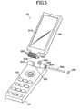
- FIG. 4 is a perspective view showing an electronic device 1 A.
- FIG. 5 is an exploded perspective view showing a hinge structure 3 A broken-down to a first casing 2 A and a second casing 8 A set apart from each other.
- FIG. 6 is a cross-sectional view showing that surface of the hinge structure 3 A which is perpendicular to a pivot 38 A thereof.
- Common numerals are given to the individual components of the electronic device 1 A according to the second embodiment equivalent to those of the electronic device 1 according to the first embodiment with the letter “A” suffixed to the common numerals of the individual components of the electronic device 1 A according to the second embodiment.
- a plurality of wiper blades 40 A are protrusively provided on a circumferential surface 37 A of the second rotational member 35 A. Those wiper blades 40 A provided in parallel to the axial center of an shaft hole 36 A across the second rotational member 35 A from the left end thereof to the right end thereof. The wiper blades 40 A are arranged in the circumferential direction of the second rotational member 35 A. The provision of the wiper blades 40 A can allow a foreign matter to be wiped out and can suppress intrusion of a foreign matter regardless of the degree of opening of the second casing 8 A with respect to the first casing 2 A.
- the individual components of the electronic device 1 A according to the second embodiment are configured like the corresponding components of the electronic device 1 according to the first embodiment, except that a plurality of wiper blades 40 A are provided at the second rotational member 35 A.
- a wiper blade 40 B is provided at the hinge rubber 44 B and is not formed integral with a second rotational member 35 B.
- Retaining space 80 B is formed in the hinge rubber 44 B, so that the second rotational member 35 B is retained in the retaining space 80 B with the hinge rubber 44 B enclosing the second rotational member 35 B.
- a circumferential surface 45 B of the hinge rubber 44 B extends along a cylindrical surface 23 B of the first casing 2 B, forming a clearance 41 B between the circumferential surface 45 B of the hinge rubber 44 B and the cylindrical surface 23 B.
- the wiper blade 40 B is protrusively provided on the circumferential surface 45 B of the hinge rubber 44 B.
- the wiper blade 40 B is formed integral with the hinge rubber 44 B, and the wiper blade 40 B and hinge rubber 44 B are made of rubber elastic material. Even if a foreign matter enters between the wiper blade 40 B and the cylindrical surface 23 B of the first casing 2 , the wiper blade 40 B which is rubber elastic member deforms to prevent the wiper blade 40 B and the cylindrical surface 23 B from being damaged by a foreign matter.
- the individual components of the electronic device 1 B according to the third embodiment are configured like the corresponding components of the electronic device 1 according to the first embodiment, except for the foregoing configuration.
- FIG. 10 is a perspective view showing an electronic device 1 C.
- FIG. 11 is an exploded perspective view showing a hinge structure 3 C broken-down to a first casing 2 C and a second casing 8 C set apart from each other.
- FIG. 12 is a cross-sectional view showing that surface of the hinge structure 3 C which is perpendicular to a pivot 38 C thereof.
- Common numerals are given to the individual components of the electronic device 1 C according to the fourth embodiment equivalent to those of the electronic device 1 B according to the third embodiment with the letter “C” suffixed to the common numerals of the individual components of the electronic device 1 C according to the fourth embodiment.
- a plurality of wiper blades 40 C are protrusively provided on a circumferential surface 45 C of a hinge rubber 44 C. Those wiper blades 40 C are arranged in the circumferential direction of the hinge rubber 44 C.
- the individual components of the electronic device 1 C according to the fourth embodiment are configured like the corresponding components of the electronic device 1 B according to the third embodiment, except that a plurality of wiper blades 40 C are provided at the hinge rubber 44 C.
- FIG. 13 is a perspective view showing an electronic device 1 D.
- FIG. 14 is an enlarged front view showing a region D shown in FIG. 13
- FIG. 15 is an exploded perspective view showing a hinge structure 3 D broken-down to a first casing 2 D and a second casing 8 D set apart from each other.
- Common numerals are given to the individual components of the electronic device 1 D according to the fifth embodiment equivalent to those of the electronic device 1 according to the first embodiment with the letter “D” suffixed to the common numerals of the individual components of the electronic device 1 D according to the fifth embodiment.
- the electronic device 1 D according to the fifth embodiment is identical to the electronic device 1 according to the first embodiment in that the operational units 21 , 21 D are provided on the front side of the first casings 2 , 2 D, respectively, and the display units 81 , 81 D are provided on the front side of the second casings 8 , 8 D, respectively.
- the hinge structure 3 D of the electronic device 1 D differs from the hinge structure 3 of the electronic device 1 , the hinge structure 3 D will be elaborated below.
- the hinge structure 3 D includes two first rotational members 31 D, 33 D provided at the first casing 2 D, a second rotational member 35 D provided at the second casing 8 D, a third rotational member 50 D intervening between the first rotational member 31 D and the second rotational member 35 D, a third rotational member 60 D intervening between the first rotational member 33 D and the second rotational member 35 D, a pivot 38 D put through those rotational members 311 D, 33 D, 35 D, 50 D and 60 D, a wiper blade 40 D bridged between the third rotational members 50 D, 60 D, a cover 39 D which closes an shaft hole 34 D of the first rotational member 33 D from the side, ring-shaped rubbers 71 D, 72 D wound around the third rotational member 50 D, and ring-shaped rubbers 73 D, 74 D wound around the third rotational member 60 D.
- One of the first rotational members, 31 D is provided at the upper end portion of the first casing 2 D on the left-hand side, while the other first rotational member 33 D is provided at the upper end portion of the first casing 2 D on the right-hand side.
- Shaft holes 32 D, 34 D are respectively formed in the first rotational members 31 D, 33 D.
- a recessed cylindrical surface 23 D (shown in FIGS. 18A to 18D and FIGS. 20A to 20D ) is formed at the upper end portion of the first casing 2 D between the first rotational members 31 D, 33 D.
- Shaft holes 51 D, 61 D are respectively formed in the third rotational members 50 D, 60 D, and are concentric to each other.
- the pivot 38 D is put through the shaft hole 34 D from the right side of the first rotational member 33 D, and is then put through the shaft hole 61 D of the third rotational member 60 D, the shaft hole 36 D of the second rotational member 35 D, the shaft hole 51 D of the third rotational member 50 D and the shaft hole 32 D of the first rotational member 31 D in order.
- Those rotational members 31 D, 33 D, 35 D, 50 D and 60 D are pivotally supported by the pivot 38 D.
- the third rotational members 50 D, 60 D are coupled to the first rotational members 31 D, 33 D by the pivot 38 D in such a way as to be rotatable relative to the first rotational members 31 D, 33 D.
- the third rotational members 50 D, 60 D are coupled to the second rotational member 35 D by the pivot 38 D in such a way as to be rotatable relative to the second rotational member 35 D.
- the third rotational members 50 D, 60 D are coupling members which are movable relative to the first casing 2 D along the cylindrical surface 23 D (shown in FIGS. 18A to 18D and FIGS. 20A to 20D ) which is a part of the top surface of the first casing 2 D.
- FIGS. 16 and 17 are exploded perspective views showing the essential portions of the hinge structure 3 D.
- an arcuate first groove 56 D with the center line of the shaft hole 32 D being the center is formed at a right side surface of the first rotational member 31 D (surface on the third rotational member 50 D side).
- a first pin 55 D is protrusively provided on the left side surface of the third rotational member 50 D (surface on the first rotational member 31 D side).
- the distance from the center line of the shaft hole 51 D to the pin 55 D is set equal to the diameter of the groove 56 D with the shaft hole 32 D being the center, and the pin 55 D is inserted in the groove 56 D.
- the pin 55 D is movable along the groove 56 D.
- Both end portions 57 D, 58 D of the groove 56 D serve as stoppers, so that the rotatable range of the third rotational member 50 D with respect to the first rotational member 31 D is restricted to a range from the position where the pin 55 D abuts on one end portion 57 D of the groove 56 D to the position where the pin 55 D abuts on the other end portion 58 D of the groove 56 D.
- the pin 55 D may be formed on the right side surface of the first rotational member 31 D
- the groove 56 D may be formed on the left side surface of the third rotational member 50 D.
- an arcuate groove 66 D is formed in the first rotational member 33 D, and a pin 65 D is protrusively provided on the third rotational member 60 D, and is inserted in the groove 66 D. Accordingly, the rotatable range of the third rotational member 60 D with respect to the first rotational member 33 D is restricted to a range from the position where the pin 65 D abuts on one end portion 67 D of the groove 66 D to the position where the pin 65 D abuts on the other end portion 68 D of the groove 66 D.
- An arcuate second groove 52 D with the center line of the shaft hole 51 D being the center is formed at a right side surface of the third rotational member 50 D (surface on the second rotational member 35 D side).
- a second pin 59 D is protrusively provided on the left side surface of the second rotational member 35 D (surface on the third rotational member 50 D side).
- the distance from the center line of the shaft hole 36 D to the pin 59 D is set equal to the diameter of the groove 52 D with the shaft hole 51 D being the center, and the pin 59 D is inserted in the groove 52 D.
- the pin 59 D is movable along the groove 52 D.
- Both end portions 53 D, 54 D of the groove 52 D serve as stoppers, so that the rotatable range of the third rotational member 50 D with respect to the second rotational member 35 D is restricted to a range from the position where the pin 59 D abuts on one end portion 53 D of the groove 52 D to the position where the pin 59 D abuts on the other end portion 54 D of the groove 52 D.
- the pin 59 D may be formed on the right side surface of the third rotational member 50 D
- the groove 52 D may be formed on the left side surface of the second rotational member 35 D.
- an arcuate groove 62 D is formed in the third rotational member 60 D, and a pin 69 D is protrusively provided on the second rotational member 35 D, and is inserted in the groove 62 D. Accordingly, the rotatable range of the third rotational member 60 D with respect to the second rotational member 35 D is restricted to a range from the position where the pin 69 D abuts on one end portion 63 D of the groove 62 D to the position where the pin 69 D abuts on the other end portion 64 D of the groove 62 D.
- the wiper blade 40 D is formed integral with the third rotational members 50 D, 60 D.
- the wiper blade 40 D abuts on the circumferential surface 37 D of the second rotational member 35 D in parallel to the shaft hole 36 D of the second rotational member 35 D.
- the wiper blade 40 D may be a rubber elastic member or a brush.
- a rubber 71 D fills the clearance between the second rotational member 35 D and the third rotational member 50 D
- a rubber 72 D fills the clearance between the first rotational member 31 D and the third rotational member 50 D
- a rubber 73 D fills the clearance between the second rotational member 35 D and the third rotational member 60 D
- a rubber 74 D fills the clearance between the first rotational member 33 D and the third rotational member 60 D.
- FIGS. 18A to 18D and FIGS. 20A to 20D are cross-sectional views taken along the line A-A shown in FIG. 14 as seen from the arrowhead direction
- FIGS. 19A to 19D and FIGS. 21A to 21D are cross-sectional views taken along the line B-B shown in FIG. 14 as seen from the arrowhead direction
- FIGS. 18A to 18D and FIGS. 19A to 19D show the operation of opening the first casing 2 D and the second casing 8 D in order
- FIGS. 20A to 20D and FIGS. 21A to 21D show the operation of opening the first casing 2 D and the second casing 8 D in order.
- the pin 69 D is positioned on the end portion 64 D side of the groove 62 D, the pin 65 D abuts on the end portion 67 D of the groove 66 D, and the wiper blade 40 D is positioned at one opening 42 D of the clearance 41 D to close the opening 42 D.
- the pin 59 D is positioned on the end portion 54 D side of the groove 52 D, and the pin 55 D abuts on the end portion 57 D of the groove 56 D.
- the second rotational member 35 D rotates with respect to the third rotational members 50 D, 60 D, causing the pins 59 D, 69 D to move toward the end portion 63 D side from the end portion 64 D side of the groove 62 D.
- the pins 55 D, 65 D are not moved away from the end portion 57 D, 67 D of the grooves 56 D, 66 D. This keeps one opening 42 D of the clearance 41 D closed with the wiper blade 40 D.
- the third rotational members 50 D, 60 D rotate with respect to the first rotational members 31 D, 33 D, so that the pins 55 D, 65 D are moved away from one end portions 57 D, 67 D of the grooves 56 D, 66 D toward the other end portions 58 D, 68 D, and the wiper blade 40 D is moved in the clearance 41 D from one opening 42 D toward the other opening 43 D.
- the wiper blade 40 D is moved in the clearance 41 D from one opening 42 D toward the other opening 43 D.
- the second casing 8 D does not further rotate in the opening direction with respect to the third rotational members 50 D, 60 D. Therefore, the first casing 2 D and the second casing 8 D do not open by more than 170 degrees. In this state, the wiper blade 40 D is positioned at the other opening 43 D of the clearance 41 D to close the opening 43 D.
- the second rotational member 35 D rotates with respect to the third rotational members 50 D, 60 D, so that the pins 59 D, 69 D move from the end portion 63 D side of the groove 62 D toward the end portion 64 D side. Because the third rotational members 50 D, 60 D do not rotate with respect to the first rotational members 31 D, 33 D at this time, the pins 55 D, 65 D are not moved away from the end portions 58 D, 68 D of the grooves 56 D, 66 D. This keeps the opening 43 D of the clearance 41 D closed with the wiper blade 40 D.
- the pins 55 D, 65 D are moved away from the end portions 58 D, 68 D of the grooves 56 D, 66 D toward the opposite end portions 57 D, 67 D, and the wiper blade 40 D is moved in the clearance 41 D from the opening 43 D toward the other opening 42 D.
- the wiper blade 40 D can be wiped out with the wiper blade 40 D.
- the angle from the opening 42 D of the clearance 41 D to the opening 43 D thereof about the pivot 38 D is narrower than the angle by which the second casing 8 D is rotatable with respect to the first casing 2 D.
- the third rotational member 50 D, 60 D intervenes between the first rotational member 3 D, 33 D and the second rotational member 35 D, so that the third rotational members 50 D, 60 D are rotatable with respect to the first rotational member 31 D, 33 D as well as the second rotational member 35 D.
- the range where the third rotational members 50 D, 60 D are rotatable with respect to the first rotational members 31 D, 33 D is defined by the grooves 56 D, 66 D
- the range where the third rotational members 50 D, 60 D is rotatable with respect to the second rotational member 35 D is defined by the grooves 52 D, 62 D.
- the rotatable ranges of the third rotational members 50 D, 60 D and the wiper blade 40 D can be set by the grooves 52 D, 62 D, 56 D and 66 D to an angle ranging from the opening 42 D of the clearance 41 D to the opening 43 D thereof about the pivot 38 D.
- FIG. 22 is a front view showing an electronic device 1 E according to the sixth embodiment of the invention
- FIG. 23 is a cross-sectional view taken along the line XXIII-XXIII in FIG. 22 as seen from the arrowhead direction
- FIG. 24 is a cross-sectional view taken along the line XXIV-XXIV in FIG. 22 as seen from the arrowhead direction.
- An operational unit 21 E is provided at the front lower portion of a first casing 2 E.
- the operational unit 21 E has a plurality of key tops 22 E, and push switches or the like corresponding to the individual key tops 22 E.
- the rear side of a second casing 8 E is coupled to the front side of the first casing 2 E by a slide mechanism 90 E.
- the second casing 8 E is a coupling member movable relative to the first casing 2 E. That is, the slide mechanism 90 E allows the second casing 8 E to be slidable up and down and linearly relative to the first casing 2 E.
- the slidable range of the second casing 8 E is determined by the slide mechanism 90 E, ranging from the position where the entire first casing 2 E and the entire second casing 8 E overlie each other to the position where the second casing 8 E is shifted upward with respect to the first casing 2 E so that the lower portion of the second casing 8 E becomes overlying the upper portion of the first casing 2 E.
- the operational unit 21 E is exposed with the second casing 8 E being shifted upward with respect to the first casing 2 E, while the operational unit 21 E is hid by the second casing 8 E with the second casing 8 E overlying the first casing 2 E.
- a display unit 81 E having a liquid crystal display panel or an organic EL display panel is provided at the front side of the second casing 8 E. Further, an operational unit 83 E having a plurality of key tops 82 E or the like is provided on the front side of the second casing 8 E under the display unit 81 E.
- a clearance 41 E is formed between the front side of the first casing 2 E and the rear side of the second casing 8 E.
- a plurality of wiper blades 40 E are provided at a vertical intermediate portion of the rear side of the second casing 8 E.
- the wiper blades 40 E are projections extending in a direction perpendicular to the slide direction of the second casing 8 E.
- the wiper blades 40 E are arranged in line in a direction perpendicular to the slide direction of the second casing 8 E.
- the wiper blades 40 E are made of rubber elastic material or brush, and have flexibility.
- the wiper blades 40 E may be projections formed integral with the second casing 8 E and protruding from the rear side of the second casing 8 E.
- the height of the wiper blades 40 E from the rear side of the second casing 8 E as a reference position is equal to the width of the clearance 41 E, so that the top portions of the wiper blades 40 E abut on the front side of the first casing 2 E.
- the top portions of the wiper blades 40 E may be set apart slightly from the front side of the first casing 2 E.
- the wiper blades 40 E move upward together with the second casing 8 E. Therefore, a foreign matter having entered the clearance 41 E is wiped out to the upper opening from the clearance 41 E.
- the wiper blades 40 E are positioned to the upper opening of the clearance 41 E to close the upper opening.
- FIGS. 25A to 25D and FIGS. 26A to 26D are rear views showing an electronic device 1 F according to the seventh embodiment.
- FIGS. 25A to 25D show the process in which a display unit casing 8 F turns from a vertical elongated state to a horizontal elongated state.
- FIG. 25A shows the vertical elongated state
- FIG. 25D shows the horizontal elongated state
- FIGS. 25B and 25C show states between the vertical elongated state and the horizontal elongated state.
- FIGS. 26A to 26D show the process in which a display unit casing 8 F turns from a horizontal elongated state to a vertical elongated state.
- FIG. 26A shows the horizontal elongated state
- FIG. 26D shows the vertical elongated state
- FIGS. 26B and 26C show states between the horizontal elongated state and the vertical elongated state.
- a coupling member 100 F is coupled to the upper end portion of a main body casing 2 F via a hinge section 3 F, and the rotations of the main body casing 2 F and the coupling member 100 F by the hinge section 3 F set the main body casing 2 F and the coupling member 100 F in a closed state with the front side of the main body casing 2 F facing the front side of the coupling member 100 F, and set the main body casing 2 F and the coupling member 100 F in an open state with the front sides of the main body casing 2 F and the coupling member 100 F facing frontward.
- An operational unit having a plurality of key tops or the like is provided at the front side of the main body casing 2 F, and an electronic camera unit 29 F is provided at the rear side of the main body casing 2 F.
- the rear side of the display unit casing 8 F is coupled to the front side of the coupling member 100 F via a slide/rotary mechanism, so that the coupling member 100 F is movable relative to the display unit casing 8 F along the rear side of the display unit casing 8 F.
- the display unit casing 8 F is provided at the front side of the coupling member 100 F in such a way as to be rotatable about a vertical shaft which is slidable up and down at the front side of the coupling member 100 F.
- the display unit casing 8 F can be reciprocally turned from the vertical elongated state to the horizontal elongated state with respect to the coupling member 100 F, so that the display unit casing 8 F is symmetrical to the right and left line regardless of the horizontal elongated state or the vertical elongated state of the display unit casing 8 F.
- a display unit having a liquid crystal display panel or an organic EL display panel is provided at the front side of the display unit casing 8 F.
- a wiper blade 40 F is provided at the front side of the coupling member 100 F between the front side of the coupling member 100 F and the rear side of the display unit casing 8 F.
- the wiper blade 40 F is provided along the left edge, upper edge and right edge of the front side of the coupling member 100 F.
- the wiper blade 40 F is made of rubber elastic material or brush, and has flexibility.
- the wiper blade 40 F may be a projection formed integral with the coupling member 100 F and protruding from the rear side of the coupling member 100 F.
- the height of the wiper blade 40 F from the front side of the coupling member 100 F as a reference position is equal to the width of the clearance between the front side of the coupling member 100 F and the rear side of the display unit casing 8 F, so that the top portion of the wiper blade 40 F abuts on the rear side of the display unit casing 8 F.
- the top portion of the wiper blade 40 F may be set apart slightly from the rear side of the display unit casing 8 F.
- the present invention is not limited to those embodiments of cleaning a foreign matter with a wiper blade.
- the following will describe an embodiment that removes a foreign matter by injecting air to a clearance.
- FIG. 27 is a perspective view showing the configuration of an electronic device 1 G according to the eighth embodiment.
- FIG. 28 is an exploded perspective view of a hinge structure 3 G.
- FIG. 29A is a schematic diagram showing the cross-section of the hinge structure 3 G along the center line of a pivot 380
- FIG. 29B is a cross-sectional view taken along the line E-E in FIG. 29A as seen from the arrowhead direction
- FIG. 29C is a cross-sectional view taken along the line F-F in FIG. 29A as seen from the arrowhead direction.
- the electronic device 1 G has a small air compressor 111 G mounted to a first casing 2 G.
- the air compressor 111 G has a flexible tube 112 G at its blow port.
- the first casing 2 G is provided with a cylindrical joint member 113 G and a first passage 114 G penetrating the joint member 113 G and connected to a first rotational member 33 G.
- the tube 112 G is connected to the joint member 113 G.
- An arcuate second passage 115 G with the center line of a shaft hole 34 G being the center is formed at a first rotational member 33 G outside the shaft hole 34 G.
- the second passage 115 G penetrates the first rotational member 33 G and is connected to the first passage 114 G.
- a rubber 46 G serves to cancel a clearance between the first rotational member 33 G and the second rotational member 35 G and to set the passages airtight from outside the electronic device 1 G.
- a cover 39 G serves to close the shaft hole 34 G and to set the passages airtight from outside the electronic device 1 G.
- Compressed air from the air compressor 111 G is injected to a clearance 41 G through the tube 112 G, the first passage 114 G, the second passage 115 G, the cylindrical groove 116 G, the third passage 117 G, and the air injection port 118 G to discharge a penetrated foreign matter.
- the injection timing is set in such a way that the opening/closing of the electronic device 1 G is detected by an open/close switch (not shown) provided at the first casing 2 G and air injection is carried out for a predetermined time under the control of a microcomputer (not shown) incorporated in the first casing 2 G.
- FIG. 30 is a perspective view showing an electronic device 1 H.
- FIG. 31 is an exploded perspective view of a hinge structure 31 H as seen from the arrowhead direction.
- FIG. 32A is a schematic cross-sectional view taken along a center line of a pivot 38 H of the hinge section 3 H
- FIG. 32B is a schematic cross-sectional view taken along the line G-G shown in FIG. 32A .
- FIGS. 32A and 32B show closing motion by a second casing 8 H with respect to a first casing 2 H.
- FIG. 33 A is a schematic cross-sectional view taken along a center line of a pivot 38 H of the hinge section 3 H
- FIG. 33B is a schematic cross-sectional view taken along the line H-H shown in FIG. 33A .
- FIGS. 33A and 33B show opening motion by a second casing 8 H with respect to a first casing 2 H.
- Common numerals are given to the individual components of the electronic device 1 H according to the ninth embodiment equivalent to those of the electronic device 1 according to the first embodiment with the letter “H” suffixed to the common numerals of the individual components of the electronic device 1 H according to the ninth embodiment.
- the electronic device 1 H has an air compressing mechanism which operates by rotation of the first casing 2 H and the second casing 8 H.
- a fan-shaped groove 121 H and a cylindrical groove 122 H are formed along the center line of a shaft hole 34 H in a first rotational member 33 H.
- a spline is formed at one end of the pivot 38 H.
- a spline corresponding to the pivot 38 H is formed at a shaft hole 36 H of a second rotational member 35 H.
- a vane 123 H is a rubber molded article having a cylindrical portion 124 H and a blade portion 125 H provided at the circumferential surface of the cylindrical portion 124 H so as to extend along the center line thereof.
- a cover 39 H is provided with a shaft groove 126 H corresponding to the pivot 38 H, a vent hole 127 H and a check valve 128 H.
- the first casing 2 H is provided with a first passage 129 H connected to the fan-shaped groove 121 H, a second passage 130 H extending along a cylindrical surface 23 H, and air injection ports 131 H connecting to the cylindrical surface 23 H from the second passage 130 H.
- the first passage 129 H and the second passage 130 H are coupled by a flexible tube 132 H to communicate with each other.
- a check valve 136 H is provided to one end of the tube 132 H and prevents the counterflow of air from an air injection port 131 H.
- the pivot 38 H is inserted in the cylindrical portion 124 H of the vane 123 H.
- the inside diameter of the cylindrical portion 124 H is set slightly smaller than the outside diameter of the pivot 38 H, so that the vane 123 H is coupled to the pivot 38 H.
- pivot 38 H passes through the shaft hole 34 H of the first rotational member 33 H to be coupled to the shaft hole 36 H of the second rotational member 35 H by the spline.
- the other end of the pivot 38 H is pivotally supported by the shaft groove 126 H of the cover 39 H.
- the cylindrical portion 124 H of the vane 123 H is held by the cylindrical surface of the cylindrical groove 122 H of the first rotational member 33 H and the pivot 38 H, and the blade portion 125 H is in contact with the wall surface of fan-shaped space 133 H surrounded by the fan-shaped groove 121 H and the cover 39 H, so that the vane 123 H partitions the fan-shaped space 133 H into an air chamber 134 H and a compression chamber 135 H.
- the vent hole 127 H is positioned near the circumferential end face of the air chamber 134 H
- the check valve 128 H is positioned near the circumferential end face of the compression chamber 135 H.
- the check valve 128 enables air suction into the compression chamber 135 H and inhibits discharge from the compression chamber 135 H.
- a filter 137 H is provided to the outside of the cover 39 H, which prevents entry of a foreign-matter into the fan-shaped space 133 H.
- the same mechanism as the air compressing mechanism structured at the first rotational member 33 H is also arranged at a first rotational member 31 H, so that compressed airs merge at the second passage 130 H.
- a passage communicating with the second rotational member may be formed at the first rotational member(s) 31 H and/or 33 H, and passages and air injection ports may be formed at the second rotational member 35 H.
- the air compressing mechanisms independently provided at the first rotational members 31 H, 33 H may have independent passages and air injection ports provided thereat, so that the first rotational members 31 H, 33 H carry out air injection at the time of opening and at the time of closing, respectively.
- This embodiment has a hinge cover which is elastically displaced within a clearance.
- FIG. 34 is a perspective view showing an electronic device 1 I.
- FIG. 35A is an exploded perspective view of a hinge structure 3 I
- FIG. 35B is a perspective view showing a hinge cover 141 I of the hinge structure 3 I.
- FIG. 36 is a schematic diagram showing the cross-section of the hinge structure 3 I along the rotational axial center thereof.
- the hinge cover 141 I is a cylindrical resin molded article, and has an opening 142 I.
- a vibrator 144 I is provided so as to be in proximity to, or in contact with, the hinge cover 144 I.
- the vibrator may double as incoming-call alert vibrator.
- An elastic ring 143 I is a rubber molded article, and has an outside diameter equivalent to the inside diameter of the hinge cover 141 I, and an inside diameter equivalent to the outside diameter of a pivot 38 I.
- a second rotational member 35 I is inserted in the hinge cover 141 I through the opening 142 I, and is enclosed in the hinge cover 141 I. It is to be noted that the circumferential surface of the second rotational member 35 I and the inner surface of the hinge cover 141 I are not fixed and have a clearance 41 I therebetween.
- the elastic ring 143 I is inserted into the cylindrical portion of the hinge cover 141 I from both ends.
- the pivot 38 I passes through a shaft hole 34 I, one elastic ring 143 I, a shaft hole 36 I, the other elastic ring 143 I, and a shaft hole 31 I to couple the hinge structure 3 I.
- the rotation of the second rotational member 35 I causes a second casing 8 I to abut on the end face of the opening 142 I, so that the hinge cover 141 I rotates with the rotation of the second rotational member 35 I.
- the hinge cover 141 I is elastically held at the pivot 38 I by the elastic ring 143 I, and always has a clearance with other elements, so that the hinge cover 141 I can be elastically moved within a clearance 41 I formed between the hinge cover 141 I and a cylindrical surface 23 I.
- the hinge cover 141 I can easily be moved manually for the cleaning purpose.
- the hinge cover 141 I is vibrated by a vibrator (not shown) incorporated in a first casing 2 I to easily discharge a foreign matter.
- a spring elastic member such as a spiral spring, may be used for the means that elastically holds the hinge cover 141 I at the pivot 38 I.
- the hinge cover 141 I and the elastic ring 143 I may be integrally formed of an elastic material, in which case cleaning becomes easier for the hinge cover 141 I itself is deformable.
- the vibrator may operate in conjunction with the operation of incoming call alert. Further, the position to dispose the vibrator 144 I is not limited to the proximity to the hinge cover 141 I, and can be arbitrary.
- timing for cleaning the mechanisms shown in the eighth and tenth embodiments can be irrelevant to the open or close of the electronic device, and injection or vibration may be performed for a predetermined time period triggered by a predetermined operation of a switch (or the operational unit 21 I).
Landscapes
- Engineering & Computer Science (AREA)
- Signal Processing (AREA)
- Telephone Set Structure (AREA)
Abstract
Description
Claims (1)
Applications Claiming Priority (4)
| Application Number | Priority Date | Filing Date | Title |
|---|---|---|---|
| JP2008003278 | 2008-01-10 | ||
| JP2008-003278 | 2008-01-10 | ||
| JP2008-315115 | 2008-12-10 | ||
| JP2008315115A JP4537480B2 (en) | 2008-01-10 | 2008-12-10 | CONNECTION DEVICE AND ELECTRONIC DEVICE |
Publications (2)
| Publication Number | Publication Date |
|---|---|
| US20090178240A1 US20090178240A1 (en) | 2009-07-16 |
| US8707516B2 true US8707516B2 (en) | 2014-04-29 |
Family
ID=40849388
Family Applications (1)
| Application Number | Title | Priority Date | Filing Date |
|---|---|---|---|
| US12/352,466 Expired - Fee Related US8707516B2 (en) | 2008-01-10 | 2009-01-12 | Coupling device and electronic device |
Country Status (1)
| Country | Link |
|---|---|
| US (1) | US8707516B2 (en) |
Cited By (5)
| Publication number | Priority date | Publication date | Assignee | Title |
|---|---|---|---|---|
| US20130312549A1 (en) * | 2012-05-22 | 2013-11-28 | Wistron Corporation | Portable computer device and screw rod device |
| US20160017649A1 (en) * | 2014-07-17 | 2016-01-21 | Seiko Epson Corporation | Opening/closing device that opens and closes opening/closing member, and image reading apparatus |
| US11243566B2 (en) | 2019-10-18 | 2022-02-08 | Samsung Electronics Co., Ltd. | Foldable electronic device having dustproof structure |
| US11406028B2 (en) * | 2019-05-29 | 2022-08-02 | Samsung Electronics Co., Ltd. | Electronic device including protective hinge structure preventing foreign matter from entering electronic device |
| US12026020B2 (en) | 2021-04-21 | 2024-07-02 | Nokia Technologies Oy | Dust mitigation |
Families Citing this family (3)
| Publication number | Priority date | Publication date | Assignee | Title |
|---|---|---|---|---|
| CN102970839B (en) * | 2011-08-29 | 2015-06-03 | 扬升照明股份有限公司 | Pivoting device |
| CN106837032B (en) * | 2017-01-04 | 2024-05-03 | 佛山市顺德区科能实业有限公司 | Lower hinge of inwardly opened and inwardly inverted window |
| JP6874705B2 (en) * | 2018-01-31 | 2021-05-19 | オムロン株式会社 | Electronics |
Citations (10)
| Publication number | Priority date | Publication date | Assignee | Title |
|---|---|---|---|---|
| US3422486A (en) * | 1966-05-23 | 1969-01-21 | Henry Thomas Jr | Automotive vehicle door hinge cover member |
| US4254532A (en) * | 1978-11-03 | 1981-03-10 | Modern Suspension Systems, Inc. | Caster apparatus |
| US4835905A (en) * | 1988-02-29 | 1989-06-06 | Schlage Lock Company | Door position indicator for a door closer |
| US5163204A (en) * | 1990-07-09 | 1992-11-17 | Jackson Christopher B | Marine door movement control apparatus |
| WO1998029630A1 (en) | 1996-12-26 | 1998-07-09 | Baer Austin R | Continuous hinge with a longitudinally supported portion and a longitudinally free end |
| US5991975A (en) * | 1997-11-05 | 1999-11-30 | Baer; Austin R. | Covered pinned hinge |
| JP2001136252A (en) | 1999-11-08 | 2001-05-18 | Nec Shizuoka Ltd | Portable terminal |
| JP2004153597A (en) | 2002-10-31 | 2004-05-27 | Sanyo Electric Co Ltd | Slide type radio terminal unit |
| JP2004161473A (en) | 2002-11-15 | 2004-06-10 | Ricoh Co Ltd | Foreign matter removal device and image forming apparatus |
| JP2006345283A (en) | 2005-06-09 | 2006-12-21 | Sharp Corp | Casing structure of electronic apparatus |
-
2009
- 2009-01-12 US US12/352,466 patent/US8707516B2/en not_active Expired - Fee Related
Patent Citations (10)
| Publication number | Priority date | Publication date | Assignee | Title |
|---|---|---|---|---|
| US3422486A (en) * | 1966-05-23 | 1969-01-21 | Henry Thomas Jr | Automotive vehicle door hinge cover member |
| US4254532A (en) * | 1978-11-03 | 1981-03-10 | Modern Suspension Systems, Inc. | Caster apparatus |
| US4835905A (en) * | 1988-02-29 | 1989-06-06 | Schlage Lock Company | Door position indicator for a door closer |
| US5163204A (en) * | 1990-07-09 | 1992-11-17 | Jackson Christopher B | Marine door movement control apparatus |
| WO1998029630A1 (en) | 1996-12-26 | 1998-07-09 | Baer Austin R | Continuous hinge with a longitudinally supported portion and a longitudinally free end |
| US5991975A (en) * | 1997-11-05 | 1999-11-30 | Baer; Austin R. | Covered pinned hinge |
| JP2001136252A (en) | 1999-11-08 | 2001-05-18 | Nec Shizuoka Ltd | Portable terminal |
| JP2004153597A (en) | 2002-10-31 | 2004-05-27 | Sanyo Electric Co Ltd | Slide type radio terminal unit |
| JP2004161473A (en) | 2002-11-15 | 2004-06-10 | Ricoh Co Ltd | Foreign matter removal device and image forming apparatus |
| JP2006345283A (en) | 2005-06-09 | 2006-12-21 | Sharp Corp | Casing structure of electronic apparatus |
Cited By (9)
| Publication number | Priority date | Publication date | Assignee | Title |
|---|---|---|---|---|
| US20130312549A1 (en) * | 2012-05-22 | 2013-11-28 | Wistron Corporation | Portable computer device and screw rod device |
| US8861212B2 (en) * | 2012-05-22 | 2014-10-14 | Wistron Corporation | Portable computer device and screw rod device |
| US20160017649A1 (en) * | 2014-07-17 | 2016-01-21 | Seiko Epson Corporation | Opening/closing device that opens and closes opening/closing member, and image reading apparatus |
| US9456099B2 (en) * | 2014-07-17 | 2016-09-27 | Seiko Epson Corporation | Opening/closing device that opens and closes opening/closing member, and image reading apparatus |
| US11406028B2 (en) * | 2019-05-29 | 2022-08-02 | Samsung Electronics Co., Ltd. | Electronic device including protective hinge structure preventing foreign matter from entering electronic device |
| US20220369476A1 (en) * | 2019-05-29 | 2022-11-17 | Samsung Electronics Co., Ltd. | Electronic device including protective hinge structure preventing foreign matter from entering electronic device |
| US12096572B2 (en) * | 2019-05-29 | 2024-09-17 | Samsung Electronics Co., Ltd | Device including hinge structure preventing foreign matter from entering electronic device |
| US11243566B2 (en) | 2019-10-18 | 2022-02-08 | Samsung Electronics Co., Ltd. | Foldable electronic device having dustproof structure |
| US12026020B2 (en) | 2021-04-21 | 2024-07-02 | Nokia Technologies Oy | Dust mitigation |
Also Published As
| Publication number | Publication date |
|---|---|
| US20090178240A1 (en) | 2009-07-16 |
Similar Documents
| Publication | Publication Date | Title |
|---|---|---|
| US8707516B2 (en) | Coupling device and electronic device | |
| US7530145B2 (en) | Cover restricting mechanism for foldable electronic device | |
| US7436653B2 (en) | Housing mechanism for electronic device and method for making the same | |
| US7522946B2 (en) | Hinge apparatus for mobile communication terminals | |
| US7552512B2 (en) | Hinge assembly for a foldable electronic device | |
| US8150483B2 (en) | Sliding mechanism and portable electronic device having the same | |
| US7565717B2 (en) | Hinge assembly | |
| US20060123596A1 (en) | Hinge assembly for a foldable electronic device | |
| US8453299B2 (en) | Connecting module and sliding mechanism for electronic device | |
| US20110043452A1 (en) | Key button mechanism and electronic device using the same | |
| JP4618588B2 (en) | Portable electronic devices | |
| JP4537480B2 (en) | CONNECTION DEVICE AND ELECTRONIC DEVICE | |
| US7561687B2 (en) | Hinge assembly for a foldable electronic device | |
| US7493674B2 (en) | Cover restricting mechanism of foldable electronic device | |
| KR100773679B1 (en) | Mobile phone of foldable and slidable type | |
| KR101009933B1 (en) | Hinge apparatus of folder type portable terminal | |
| JP4619343B2 (en) | Foldable mobile terminal | |
| US20140115828A1 (en) | Hinge structure with cushioning module | |
| KR200316495Y1 (en) | A rotary-typed extraction device of a cellular phone | |
| JP2005051421A (en) | Rotation angle detector and electronic equipment provided therewith | |
| KR200350771Y1 (en) | Hinge apparatus and portable phone having the same | |
| KR100982969B1 (en) | Hinge apparatus of folder type portable terminal | |
| US20070081804A1 (en) | Electronic device including a rotatable camera unit | |
| KR200378291Y1 (en) | Hinge unit having mid-stop step | |
| KR100238538B1 (en) | Hinge mechanism for flip-type portable radiophone |
Legal Events
| Date | Code | Title | Description |
|---|---|---|---|
| AS | Assignment |
Owner name: CASIO HITACHI MOBILE COMMUNICATIONS CO., LTD., JAP Free format text: ASSIGNMENT OF ASSIGNORS INTEREST;ASSIGNORS:KOYAMA, YUTAKA;KAWASAKI, YASUHIKO;REEL/FRAME:022093/0565 Effective date: 20081219 |
|
| AS | Assignment |
Owner name: NEC CASIO MOBILE COMMUNICATIONS, LTD., JAPAN Free format text: MERGER;ASSIGNOR:CASIO HITACHI MOBILE COMMUNICATIONS, CO., LTD.;REEL/FRAME:024700/0299 Effective date: 20100601 |
|
| AS | Assignment |
Owner name: NEC CORPORATION, JAPAN Free format text: ASSIGNMENT OF ASSIGNORS INTEREST;ASSIGNOR:NEC CASIO MOBILE COMMUNICATION LTD.;REEL/FRAME:030258/0429 Effective date: 20130301 |
|
| AS | Assignment |
Owner name: LENOVO INNOVATIONS LIMITED (HONG KONG), HONG KONG Free format text: ASSIGNMENT OF ASSIGNORS INTEREST;ASSIGNOR:NEC CORPORATION;REEL/FRAME:033720/0767 Effective date: 20140618 |
|
| FEPP | Fee payment procedure |
Free format text: MAINTENANCE FEE REMINDER MAILED (ORIGINAL EVENT CODE: REM.) |
|
| LAPS | Lapse for failure to pay maintenance fees |
Free format text: PATENT EXPIRED FOR FAILURE TO PAY MAINTENANCE FEES (ORIGINAL EVENT CODE: EXP.) |
|
| STCH | Information on status: patent discontinuation |
Free format text: PATENT EXPIRED DUE TO NONPAYMENT OF MAINTENANCE FEES UNDER 37 CFR 1.362 |
|
| FP | Lapsed due to failure to pay maintenance fee |
Effective date: 20180429 |