US8705176B2 - Modified Michelson delay-line interferometer - Google Patents

Modified Michelson delay-line interferometer Download PDF

Info

Publication number
US8705176B2
US8705176B2 US12/928,189 US92818910A US8705176B2 US 8705176 B2 US8705176 B2 US 8705176B2 US 92818910 A US92818910 A US 92818910A US 8705176 B2 US8705176 B2 US 8705176B2
Authority
US
United States
Prior art keywords
etalon
opl
time delay
location
interferometer
Prior art date
Legal status (The legal status is an assumption and is not a legal conclusion. Google has not performed a legal analysis and makes no representation as to the accuracy of the status listed.)
Active, expires
Application number
US12/928,189
Other versions
US20110134532A1 (en
Inventor
Yung-Chieh Hsieh
Current Assignee (The listed assignees may be inaccurate. Google has not performed a legal analysis and makes no representation or warranty as to the accuracy of the list.)
Optoplex Corp
Original Assignee
Optoplex Corp
Priority date (The priority date is an assumption and is not a legal conclusion. Google has not performed a legal analysis and makes no representation as to the accuracy of the date listed.)
Filing date
Publication date
Priority claimed from US11/360,959 external-priority patent/US20060268277A1/en
Priority claimed from US11/485,653 external-priority patent/US7522343B2/en
Application filed by Optoplex Corp filed Critical Optoplex Corp
Priority to US12/928,189 priority Critical patent/US8705176B2/en
Assigned to OPTOPLEX CORPORATION reassignment OPTOPLEX CORPORATION ASSIGNMENT OF ASSIGNORS INTEREST (SEE DOCUMENT FOR DETAILS). Assignors: HSIEH, YUNG-CHIEH
Publication of US20110134532A1 publication Critical patent/US20110134532A1/en
Priority to US14/242,712 priority patent/US20140211314A1/en
Application granted granted Critical
Publication of US8705176B2 publication Critical patent/US8705176B2/en
Active legal-status Critical Current
Adjusted expiration legal-status Critical

Links

Images

Classifications

    • GPHYSICS
    • G02OPTICS
    • G02BOPTICAL ELEMENTS, SYSTEMS OR APPARATUS
    • G02B27/00Optical systems or apparatus not provided for by any of the groups G02B1/00 - G02B26/00, G02B30/00
    • G02B27/10Beam splitting or combining systems
    • G02B27/14Beam splitting or combining systems operating by reflection only
    • G02B27/144Beam splitting or combining systems operating by reflection only using partially transparent surfaces without spectral selectivity
    • HELECTRICITY
    • H04ELECTRIC COMMUNICATION TECHNIQUE
    • H04BTRANSMISSION
    • H04B10/00Transmission systems employing electromagnetic waves other than radio-waves, e.g. infrared, visible or ultraviolet light, or employing corpuscular radiation, e.g. quantum communication
    • H04B10/60Receivers
    • H04B10/66Non-coherent receivers, e.g. using direct detection
    • H04B10/67Optical arrangements in the receiver
    • H04B10/676Optical arrangements in the receiver for all-optical demodulation of the input optical signal
    • H04B10/677Optical arrangements in the receiver for all-optical demodulation of the input optical signal for differentially modulated signal, e.g. DPSK signals
    • GPHYSICS
    • G02OPTICS
    • G02BOPTICAL ELEMENTS, SYSTEMS OR APPARATUS
    • G02B5/00Optical elements other than lenses
    • G02B5/20Filters
    • G02B5/28Interference filters
    • G02B5/284Interference filters of etalon type comprising a resonant cavity other than a thin solid film, e.g. gas, air, solid plates

Definitions

  • the present invention relates to differential phase-shift keying (DPSK) in telecommunication, and more specifically, it relates to methods in DPSK for converting a phase-keyed signal to an intensity-keyed signal.
  • DPSK differential phase-shift keying
  • Phase-shift keying is a digital modulation scheme that conveys data by changing, or modulating, the phase of a reference signal (the carrier wave). Any digital modulation scheme uses a finite number of distinct signals to represent digital data. In the case of PSK, a finite number of phases are used. Each of these phases is assigned a unique pattern of binary bits. Usually, each phase encodes an equal number of bits. Each pattern of bits forms the symbol that is represented by the particular phase.
  • the demodulator which is designed specifically for the symbol-set used by the modulator, determines the phase of the received signal and maps it back to the symbol it represents, thus recovering the original data. This requires the receiver to be able to compare the phase of the received signal to a reference signal—such a system is termed coherent.
  • DPSK differential phase-shift keying
  • differential phase-shift keying requires a decoding method in order to convert the phase-keyed signal to an intensity-keyed signal at the receiving end.
  • the decoding method can be achieved by comparing the phase of two sequential bits. In principle, it splits the input signal beam into two channels with a small delay before recombining them. After the recombination, the beams from the two channels interfere constructively or destructively. The interference intensity is measured and becomes the intensity-keyed signal.
  • one channel has an optical path longer than the other one by a distance equivalent to the photon flight time of one bit. For instance, in a 40 Gbit per second system, one bit is equal to 25 ps, and light travels 7.5 mm in that period. In this example, the optical path difference (OPD) between the two channels is 7.5 mm.
  • Another object is to provide a DPSK demodulator with a desired time delay between the two interference arms using one etalon in each arm of a DLI.
  • Another object is to provide a DPSK demodulator with a desired time delay between the two interference arms using two etalons with the same FSR.
  • Another object is to provide a DPSK demodulator with a desired time delay between the two interference arms using two etalons with the same FSR, which is equal to ITU frequency spacing.
  • Another object is to provide the desired time delay, which is almost constant within the pass band of the channel.
  • An optical etalon with a fixed FSR, determined by the cavity length, the time delay can be adjusted by the coating.
  • the proper cavity length can therefore be chosen to achieve a desired FSR, and the coating can be independently selected to obtain a desired time delay.
  • FIG. 1 shows a Michelson DLI
  • FIG. 2 shows a GT etalon
  • FIG. 3 shows a 2GT-mirror
  • FIG. 4A shows the power spectrum of the design of FIG. 3 .
  • FIGS. 5A and 5B are magnifications of portions of FIGS. 4A and 4B respectively.
  • FIG. 6 shows a GT-AP-mirror
  • FIG. 7A shows the power spectrum of the design of FIG. 8 .
  • FIGS. 8A and 8B are magnifications of portions of FIGS. 7A and 7B respectively.
  • FIG. 9 shows a Mirror-GT.
  • FIG. 10A shows the power spectrum of the design of FIG. 9 .
  • FIGS. 11A and 11B are magnifications of portions of FIGS. 10A and 10B respectively.
  • FIG. 12 shows a GT-AP-GT.
  • FIG. 13A shows the power spectrum of the design of FIG. 12 .
  • FIGS. 14A and 14B are magnifications of portions of FIGS. 13A and 13B respectively.
  • FIG. 15 shows a GT-2AP-GT.
  • FIG. 16A shows the power spectrum of the design of FIG. 15 .
  • FIGS. 17A and 17B are magnifications of portions of FIGS. 16A and 16B respectively.
  • FIG. 1 shows a typical implementation using a Michelson interferometer.
  • Input light beam 10 passes through the entrance face 12 of beam splitter 14 and beam 10 is split at interface 16 into beams 18 and 20 .
  • Beam 18 travels upward in the figure, passing through face 22 and then is reflected by mirror 24 such that it passes back through face 22 and is split at interface 16 into beams 18 ′ and 18 ′′.
  • beam 20 travels to the right in the figure, passing through face 26 and then is reflected by mirror 28 such that it passes back through face 26 and is again split at interface 16 into beams 20 ′ and 20 ′′.
  • faces 22 and 26 are antireflection coated.
  • the two mirrors are set at different distances from beam splitter 14 .
  • the beam 18 ′ and 20 ′ are collinear in the beam travelling toward the left side of the figure and beams 18 ′′ and 20 ′′ are collinear in the beam traveling downward in the figure. Because the two mirrors are set at different distances from the beam splitter, there is a time delay between beams 18 ′ and 20 ′ and a time delay between beams 18 ′′ and 20 ′′. The time delay is due to the path length difference.
  • the path length difference corresponds to the time delay required.
  • ⁇ 1 2 ⁇ ⁇ ⁇ ⁇ ( ⁇ ⁇ 1 )
  • ⁇ 2 2 ⁇ ⁇ ⁇ ⁇ ( ⁇ ⁇ 2 )
  • ⁇ 1 C 2 ⁇ ⁇ L 1
  • ⁇ 2 C 2 ⁇ ⁇ L 2 C: Speed of light time delay
  • Equation (1) shows that the FSR (free spectral range) of the transfer function is the inverse of the time delay between the two interference arms. This is the fundamental property of the regular delay line interferometer (DLI). In such a device, the time delay and the FSR are not independent parameters. Once the time delay is chosen, the FSR is determined.
  • DLI regular delay line interferometer
  • the optimized time delay is about 15 ps rather than 23.3 ps (which corresponds to a 1 bit delay). This is the result of the balance between the overlapping of two adjacent pulses in the time domain and the phase match in the frequency domain. If exactly a one-bit delay is desired, the FSR should be 42.8 GHz. In such case, the two adjacent bits in the time domain will overlap very well. However, only the carrier frequency has 0 degree of phase error. Once the frequency is off from the carrier, the phase will not match perfectly.
  • the corresponding FSR is equal to 66.67 GHz. Since the FSR is not equal to 50 GHz or 100 GHz, which are typical channel spacing in communication channels, the peak of the transfer function do not correspond to the International Telecommunication Union (ITU) grids. This makes it very inconvenient in real application.
  • ITU International Telecommunication Union
  • the invention provides apparatuses and methods to keep the time delay as required but with all the ITU frequencies on the peak of transfer function.
  • Equation (3) shows that the time delay of an etalon can be a fraction of the cavity time constant and the amount of delay can be adjusted by the reflectivity of the PR coating.
  • the time delay can be adjusted by the coating. This invention will use this property to build a DPSK demodulator with required time delay between the two interference arms, but the FSR is equal to ITU frequency spacing.
  • the present invention adjusts the time delay and FSR independently.
  • the method is called MM-DLI (modified Michelson delay-line interferometer).
  • Equation (4) indicates that for a given FSR, one can change the coating to achieve the required bandwidth.
  • FIG. 3 to FIG. 17 show exemplary MM-DLI designs and the corresponding power spectrums and time delay curves.
  • the etalons are either 100 GHz or 50 GHz.
  • the FSR of the etalons can be any number.
  • U.S. Pat. No. 6,587,204 is incorporated herein by reference.
  • U.S. Pat. No. 7,145,727 is incorporated herein by reference.
  • FIG. 1 shows a Michelson DLL
  • FIG. 2 shows a GT etalon.
  • FIG. 3 shows a 2GT-mirror.
  • FIG. 4A shows the power spectrum of the design of FIG. 3 where the top face of the beamsplitter has a partially reflecting (PR) coating.
  • FIGS. 5A and 5B are magnifications of portions of FIGS. 4A and 4B respectively.
  • FIG. 6 shows a GT-AP-mirror.
  • FIG. 7A shows the power spectrum of the design of FIG. 8 .
  • FIGS. 8A and 8B are magnifications of portions of FIGS. 7A and 7B respectively.
  • FIG. 9 shows a Mirror-GT.
  • FIG. 10A shows the power spectrum of the design of FIG. 9 .
  • FIGS. 11A and 11B are magnifications of portions of FIGS. 10A and 10B respectively.
  • FIG. 12 shows a GT-AP-GT.
  • FIG. 13A shows the power spectrum of the design of FIG. 12 .
  • FIGS. 14A and 14B are magnifications of portions of FIGS. 13A and 13B respectively.
  • FIG. 14A and 14B are magnifications of portions of FIGS. 13A and 13B respectively.
  • FIG. 15 shows a GT-2AP-GT.
  • FIG. 16A shows the power spectrum of the design of FIG. 15 .
  • FIGS. 17A and 17B are magnifications of portions of FIGS. 16A and 16B respectively.
  • the present invention replaces a reflection mirror of the DLI with an etalon.
  • the etalon can be GT-etalon, FP etalon or other types of etalon.
  • the etalon provides a non-integer multiple of etalon time constant, time delay and the amount of delay can be adjusted by varying the reflectivity of the two surfaces on the etalon.

Abstract

In an optical etalon with a fixed FSR determined by the cavity length, the time delay is adjusted by an etalon surface coating. The proper cavity length is chosen to achieve a desired FSR, and the coating is independently selected to obtain a desired time delay.

Description

RELATED APPLICATIONS
This application is a Divisional application of Ser. No. 12/174,628, filed Jul. 16, 2008, which claims priority to U.S. Provisional Patent Application Ser. No. 60/950,142, titled: “Modified Michelson Delay Line Interferometer” filed Jul. 17, 2007 and incorporated herein by reference. This is also a continuation-in-part of U.S. patent application Ser. No. 11/485,653, titled: “Integration of Michelson Differential Phase Shift Keying (DPSK) Demodulator with Photo Detector,” filed Jul. 11, 2006, incorporated herein by reference, which is a continuation-in-part of U.S. patent application Ser. No. 11/360,959, titled: “Michelson Interferometer Based. Delay Line Interferometers,” filed Feb. 22, 2006, incorporated herein by reference.
BACKGROUND OF THE INVENTION
1. Field of the Invention
The present invention relates to differential phase-shift keying (DPSK) in telecommunication, and more specifically, it relates to methods in DPSK for converting a phase-keyed signal to an intensity-keyed signal.
2. Description of Related Art
Phase-shift keying (PSK) is a digital modulation scheme that conveys data by changing, or modulating, the phase of a reference signal (the carrier wave). Any digital modulation scheme uses a finite number of distinct signals to represent digital data. In the case of PSK, a finite number of phases are used. Each of these phases is assigned a unique pattern of binary bits. Usually, each phase encodes an equal number of bits. Each pattern of bits forms the symbol that is represented by the particular phase. The demodulator, which is designed specifically for the symbol-set used by the modulator, determines the phase of the received signal and maps it back to the symbol it represents, thus recovering the original data. This requires the receiver to be able to compare the phase of the received signal to a reference signal—such a system is termed coherent.
Alternatively, instead of using the bit patterns to set the phase of the wave, it can instead be used to change it by a specified amount. The demodulator then determines the changes in the phase of the received signal rather than the phase itself. Since this scheme depends on the difference between successive phases, it is termed differential phase-shift keying (DPSK). DPSK can be significantly simpler to implement than ordinary PSK since there is no need for the demodulator to have a copy of the reference signal to determine the exact phase of the received signal (it is a non-coherent scheme).
In telecommunication technology, differential phase-shift keying (DPSK) requires a decoding method in order to convert the phase-keyed signal to an intensity-keyed signal at the receiving end. The decoding method can be achieved by comparing the phase of two sequential bits. In principle, it splits the input signal beam into two channels with a small delay before recombining them. After the recombination, the beams from the two channels interfere constructively or destructively. The interference intensity is measured and becomes the intensity-keyed signal. To achieve this, one channel has an optical path longer than the other one by a distance equivalent to the photon flight time of one bit. For instance, in a 40 Gbit per second system, one bit is equal to 25 ps, and light travels 7.5 mm in that period. In this example, the optical path difference (OPD) between the two channels is 7.5 mm.
SUMMARY OF THE INVENTION
It is an object of the present invention to provide a DPSK demodulator with a desired time delay between the two interference arms using at least one etalon in a DLI.
Another object is to provide a DPSK demodulator with a desired time delay between the two interference arms using one etalon in each arm of a DLI.
Another object is to provide a DPSK demodulator with a desired time delay between the two interference arms using two etalons with the same FSR.
Another object is to provide a DPSK demodulator with a desired time delay between the two interference arms using two etalons with the same FSR, which is equal to ITU frequency spacing.
Another object is to provide the desired time delay, which is almost constant within the pass band of the channel.
These and other objects will be apparent based on the disclosure herein.
An optical etalon with a fixed FSR, determined by the cavity length, the time delay can be adjusted by the coating. The proper cavity length can therefore be chosen to achieve a desired FSR, and the coating can be independently selected to obtain a desired time delay.
BRIEF DESCRIPTION OF THE DRAWINGS
The accompanying drawings, which are incorporated into and form a part of the disclosure, illustrate embodiments of the invention and, together with the description, serve to explain the principles of the invention.
FIG. 1 shows a Michelson DLI
FIG. 2 shows a GT etalon.
FIG. 3 shows a 2GT-mirror.
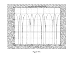
FIG. 4A shows the power spectrum of the design of FIG. 3.
FIG. 4B shows the time delay for the design of FIG. 3, with PR=3.3%.
FIGS. 5A and 5B are magnifications of portions of FIGS. 4A and 4B respectively.
FIG. 6 shows a GT-AP-mirror.
FIG. 7A shows the power spectrum of the design of FIG. 8.
FIG. 7B shows the time delay for the design of FIG. 6, with PR=1.5%.
FIGS. 8A and 8B are magnifications of portions of FIGS. 7A and 7B respectively.
FIG. 9 shows a Mirror-GT.
FIG. 10A shows the power spectrum of the design of FIG. 9.
FIG. 10B shows the time delay for the design of FIG. 9, with PR=1.5%.
FIGS. 11A and 11B are magnifications of portions of FIGS. 10A and 10B respectively.
FIG. 12 shows a GT-AP-GT.
FIG. 13A shows the power spectrum of the design of FIG. 12.
FIG. 13B shows the time delay for the design of FIG. 12, with PR1=2%, PR2=37%.
FIGS. 14A and 14B are magnifications of portions of FIGS. 13A and 13B respectively.
FIG. 15 shows a GT-2AP-GT.
FIG. 16A shows the power spectrum of the design of FIG. 15.
FIG. 16B shows the time delay for the design of FIG. 15, with PR1=37%, PR2=2%.
FIGS. 17A and 17B are magnifications of portions of FIGS. 16A and 16B respectively.
DETAILED DESCRIPTION OF THE INVENTION Michelson DPSK Demodulator
The delay line interferometer is a key component in optical communication for demodulating the phase modulated optical signal. FIG. 1 shows a typical implementation using a Michelson interferometer. Input light beam 10 passes through the entrance face 12 of beam splitter 14 and beam 10 is split at interface 16 into beams 18 and 20. Beam 18 travels upward in the figure, passing through face 22 and then is reflected by mirror 24 such that it passes back through face 22 and is split at interface 16 into beams 18′ and 18″. In similar manner, beam 20 travels to the right in the figure, passing through face 26 and then is reflected by mirror 28 such that it passes back through face 26 and is again split at interface 16 into beams 20′ and 20″. Note that faces 22 and 26 are antireflection coated. The two mirrors are set at different distances from beam splitter 14. The beam 18′ and 20′ are collinear in the beam travelling toward the left side of the figure and beams 18″ and 20″ are collinear in the beam traveling downward in the figure. Because the two mirrors are set at different distances from the beam splitter, there is a time delay between beams 18′ and 20′ and a time delay between beams 18″ and 20″. The time delay is due to the path length difference.
The path length difference, referred to in the following formulas as L1-L2, corresponds to the time delay required.
ϕ 1 = 2 π ( ν ν 1 ) ϕ 2 = 2 π ( ν ν 2 ) where ν 1 = C 2 L 1 ν 2 = C 2 L 2
C: Speed of light
time delay
τ = τ 1 - τ 2 = 2 ( L 1 - L 2 C )
The power spectrums of the transfer function for the constructive and destructive ports are as follows.
P constr = cos 2 ( ϕ 1 - ϕ 2 2 ) = cos 2 ( π ν ν τ ) P destr = sin 2 ( ϕ 1 - ϕ 2 2 ) = sin 2 ( π ν ν τ ) ν τ = 1 τ = FSR Equation ( 1 )
The 3 dB bandwidth of the transfer function is
FWHM = ν τ 2 = FSR 2 Equation ( 2 )
Equation (1) shows that the FSR (free spectral range) of the transfer function is the inverse of the time delay between the two interference arms. This is the fundamental property of the regular delay line interferometer (DLI). In such a device, the time delay and the FSR are not independent parameters. Once the time delay is chosen, the FSR is determined.
TABLE 1
Summary of the Michelson interferometer DPSK demodulator:
Time
delay FSR FWHM Delay ripple
Michelson interferometer τ 1 τ 1 2 τ 0
Therefore, to obtain a wider FWHM, a smaller time delay is require. It has been shown both theoretically and experimentally, to demodulate a 42.8 Gbit/sec of DPSK phase signal, the optimized time delay is about 15 ps rather than 23.3 ps (which corresponds to a 1 bit delay). This is the result of the balance between the overlapping of two adjacent pulses in the time domain and the phase match in the frequency domain. If exactly a one-bit delay is desired, the FSR should be 42.8 GHz. In such case, the two adjacent bits in the time domain will overlap very well. However, only the carrier frequency has 0 degree of phase error. Once the frequency is off from the carrier, the phase will not match perfectly. In contrast, if the time delay is 15 ps, a certain percentage of the pulse in the time domain will not overlap and frequency components off from the carrier frequency will also have phase mis-match. However, since the phase mis-match slope is smaller, the mis-match penalty will also be smaller.
For a 15 ps time delay, the corresponding FSR is equal to 66.67 GHz. Since the FSR is not equal to 50 GHz or 100 GHz, which are typical channel spacing in communication channels, the peak of the transfer function do not correspond to the International Telecommunication Union (ITU) grids. This makes it very inconvenient in real application.
The invention provides apparatuses and methods to keep the time delay as required but with all the ITU frequencies on the peak of transfer function.
Etalon Time Constant, Time Delay and Resonance Fundamental Frequency
For a given optical etalon with optical path length between the two reflection surfaces, LE, we have,
τ E = 2 L E C , Etalon time constant ν E = FSR = 1 τ E , Etalon resoance fundamental frequency
Etalon Time Delay
Using the first surface of the etalon as the reference surface, if the phase of the reflection beam is written as φo(ν).
For any optical device, if the phase of the transfer function is φo(ν), the time delay is
t E = 1 2 π ϕ o ν
Time Delay for Gires-Tournois (GT) Etalon
For a GT etalon,
ϕ GT = 2 tan - 1 ( α tan ( π ν ν E ) ) α = ( 1 - r 1 + r ) , 0 < α < 1 r = R R : reflectivity of the front surface ( PR coating )
When the optical frequency, v, is near the multiple integers of the resonance frequency, then
ϕ GT = 2 α π ν ν E t GT = α τ E = 2 α L E C Equation ( 3 )
TABLE 2
The time delay of a GT etalon for a few different reflectivities
R = 0 R = 1/9 R = 1
r 0 1/3 1
α 1 0.5  0
Time delay (tGT) tE 0.5t E 0
Equation (3) shows that the time delay of an etalon can be a fraction of the cavity time constant and the amount of delay can be adjusted by the reflectivity of the PR coating. In other words, for an optical etalon with a fixed FSR, which corresponds to its fundamental resonance frequency, the time delay can be adjusted by the coating. This invention will use this property to build a DPSK demodulator with required time delay between the two interference arms, but the FSR is equal to ITU frequency spacing.
Modified Michelson DLI (Delay Line Interferometer)
The present invention adjusts the time delay and FSR independently. The method is called MM-DLI (modified Michelson delay-line interferometer).
Combining Eq. (2) and (3), we have,
FWHM = 1 2 t GT = 1 2 α ν E = 1 2 α FSR Equation ( 4 )
Equation (4) indicates that for a given FSR, one can change the coating to achieve the required bandwidth.
TABLE 3
Terminology
GT GT etalon with 100 GHz FSR (~1.5 mm)
2GT GT etalon with 50 GHz FSR (~3 mm)
AP 1.5 mm space formed by an AR (anti-reflected
surface) and PR (partially reflecting coating surface)
2AP a 3 mm space formed by an AR (anti-reflected
surface) and PR (partial reflected coating surface)
mirror The ~100% reflection surface
FIG. 3 to FIG. 17 show exemplary MM-DLI designs and the corresponding power spectrums and time delay curves. In those examples, the etalons are either 100 GHz or 50 GHz. In general, the FSR of the etalons can be any number. U.S. Pat. No. 6,587,204 is incorporated herein by reference. U.S. Pat. No. 7,145,727 is incorporated herein by reference.
FIG. 1 shows a Michelson DLL FIG. 2 shows a GT etalon. FIG. 3 shows a 2GT-mirror. FIG. 4A shows the power spectrum of the design of FIG. 3 where the top face of the beamsplitter has a partially reflecting (PR) coating. FIG. 4B shows the time delay for the design of FIG. 3, with PR=3.3%. FIGS. 5A and 5B are magnifications of portions of FIGS. 4A and 4B respectively. FIG. 6 shows a GT-AP-mirror. FIG. 7A shows the power spectrum of the design of FIG. 8. FIG. 7B shows the time delay for the design of FIG. 6, with PR=15%. FIGS. 8A and 8B are magnifications of portions of FIGS. 7A and 7B respectively. FIG. 9 shows a Mirror-GT. FIG. 10A shows the power spectrum of the design of FIG. 9. FIG. 10B shows the time delay for the design of FIG. 9, with PR=15%. FIGS. 11A and 11B are magnifications of portions of FIGS. 10A and 10B respectively. FIG. 12 shows a GT-AP-GT. FIG. 13A shows the power spectrum of the design of FIG. 12. FIG. 13B shows the time delay for the design of FIG. 12, with PR1=2%, PR2=37%. FIGS. 14A and 14B are magnifications of portions of FIGS. 13A and 13B respectively. FIG. 15 shows a GT-2AP-GT. FIG. 16A shows the power spectrum of the design of FIG. 15. FIG. 16B shows the time delay for the design of FIG. 15, with PR1=37%, PR2=2%. FIGS. 17A and 17B are magnifications of portions of FIGS. 16A and 16B respectively.
Therefore, the present invention replaces a reflection mirror of the DLI with an etalon. The etalon can be GT-etalon, FP etalon or other types of etalon. The etalon provides a non-integer multiple of etalon time constant, time delay and the amount of delay can be adjusted by varying the reflectivity of the two surfaces on the etalon.
The foregoing description of the invention has been presented for purposes of illustration and description and is not intended to be exhaustive or to limit the invention to the precise form disclosed. Many modifications and variations are possible in light of the above teaching. The embodiments disclosed were meant only to explain the principles of the invention and its practical application to thereby enable others skilled in the art to best use the invention in various embodiments and with various modifications suited to the particular use contemplated. The scope of the invention is to be defined by the following claims.

Claims (14)

The invention claimed is:
1. An interferometer, comprising:
means for splitting, at a splitting location, an input light beam into a first beam and a second beam;
means for recombining, at a recombination location, said first beam and said second beam to produce at least one output beam; and
means for detecting said at least one output beam;
wherein said first beam will travel a first optical path length (OPL) from said splitting location to said recombination location;
wherein said second beam will travel a second OPL from said splitting location to said recombination location;
wherein, when said input light beam carries phase modulated data with a fixed time interval between two adjacent data symbols, then the difference in optical path lengths between said first OPL and said second OPL is about equal to said time interval multiplied by the speed of light and is set by at least one etalon placed in the path of at least one of said first beam and said second beam.
2. The interferometer of claim 1, wherein said difference in optical path lengths between said first OPL and said second OPL is set by at least one etalon placed in both paths of said first beam and second beam.
3. The interferometer of claim 2, wherein each of said at least one etalon comprises about the same FSR.
4. The interferometer of claim 3, wherein said FSR is about equal to an ITU frequency spacing.
5. The interferometer of claim 1, wherein said time interval is about constant within a pass band of a communication channel.
6. The interferometer of claim 5, wherein a surface of said etalon comprises a coating that is selected to determine a desired time delay.
7. The interferometer of claim 1, wherein a surface of said etalon comprises a coating that is selected to determine a desired time delay.
8. A method, comprising the following steps:
splitting, at a splitting location, an input light beam into a first beam and a second beam;
recombining, at a recombination location, said first beam and said second beam to produce at least one output beam; and
detecting said at least one output beam;
wherein said first beam travels a first optical path length (OPL) from said splitting location to said recombination location;
wherein said second beam travels a second OPL from said splitting location to said recombination location;
wherein, when said input light beam carries phase modulated data with a fixed time interval between two adjacent data symbols, then the difference in optical path lengths between said first OPL and said second OPL is about equal to said time interval multiplied by the speed of light and is set by at least one etalon placed in the path of at least one of said first beam and said second beam.
9. The method of claim 8, wherein said difference in optical path lengths between said first OPL and said second OPL is set by at least one etalon placed in both paths of said first beam and second beam.
10. The method of claim 9, wherein each of said at least one etalon comprises about the same FSR.
11. The method of claim 10, wherein said FSR is about equal to an ITU frequency spacing.
12. The method of claim 8, wherein said time interval is about constant within a pass band of a communication channel.
13. The method of claim 12, wherein a surface of said etalon comprises a coating that is selected to determine a desired time delay.
14. The method of claim 8, wherein a surface of said etalon comprises a coating that is selected to determine a desired time delay.
US12/928,189 2006-02-22 2010-12-06 Modified Michelson delay-line interferometer Active 2028-05-08 US8705176B2 (en)

Priority Applications (2)

Application Number Priority Date Filing Date Title
US12/928,189 US8705176B2 (en) 2006-02-22 2010-12-06 Modified Michelson delay-line interferometer
US14/242,712 US20140211314A1 (en) 2006-02-22 2014-04-01 Efficiency of a deep grating

Applications Claiming Priority (5)

Application Number Priority Date Filing Date Title
US11/360,959 US20060268277A1 (en) 2005-02-23 2006-02-22 Michelson interferometer based delay line interferometers
US11/485,653 US7522343B2 (en) 2004-03-08 2006-07-11 Michelson interferometer based delay line interferometers
US95014207P 2007-07-17 2007-07-17
US12/174,628 US7864430B2 (en) 2006-02-22 2008-07-16 Modified Michelson delay line interferometer
US12/928,189 US8705176B2 (en) 2006-02-22 2010-12-06 Modified Michelson delay-line interferometer

Related Parent Applications (1)

Application Number Title Priority Date Filing Date
US12/174,628 Division US7864430B2 (en) 2006-02-22 2008-07-16 Modified Michelson delay line interferometer

Related Child Applications (1)

Application Number Title Priority Date Filing Date
US11/360,959 Continuation-In-Part US20060268277A1 (en) 2004-03-08 2006-02-22 Michelson interferometer based delay line interferometers

Publications (2)

Publication Number Publication Date
US20110134532A1 US20110134532A1 (en) 2011-06-09
US8705176B2 true US8705176B2 (en) 2014-04-22

Family

ID=46331945

Family Applications (2)

Application Number Title Priority Date Filing Date
US12/174,628 Active 2026-09-11 US7864430B2 (en) 2006-02-22 2008-07-16 Modified Michelson delay line interferometer
US12/928,189 Active 2028-05-08 US8705176B2 (en) 2006-02-22 2010-12-06 Modified Michelson delay-line interferometer

Family Applications Before (1)

Application Number Title Priority Date Filing Date
US12/174,628 Active 2026-09-11 US7864430B2 (en) 2006-02-22 2008-07-16 Modified Michelson delay line interferometer

Country Status (1)

Country Link
US (2) US7864430B2 (en)

Families Citing this family (1)

* Cited by examiner, † Cited by third party
Publication number Priority date Publication date Assignee Title
CN102073190B (en) 2009-11-25 2013-08-07 华为技术有限公司 Optical demodulator

Citations (1)

* Cited by examiner, † Cited by third party
Publication number Priority date Publication date Assignee Title
US20090213468A1 (en) * 2004-03-08 2009-08-27 Optoplex Corporation Michelson-interferometer-based delay-line interferometers

Family Cites Families (1)

* Cited by examiner, † Cited by third party
Publication number Priority date Publication date Assignee Title
US20080240736A1 (en) * 2007-03-28 2008-10-02 Nec Laboratories America, Inc. Inter-Symbol Interference-Suppressed Colorless DPSK Demodulation

Patent Citations (1)

* Cited by examiner, † Cited by third party
Publication number Priority date Publication date Assignee Title
US20090213468A1 (en) * 2004-03-08 2009-08-27 Optoplex Corporation Michelson-interferometer-based delay-line interferometers

Also Published As

Publication number Publication date
US7864430B2 (en) 2011-01-04
US20110134532A1 (en) 2011-06-09
US20090135473A1 (en) 2009-05-28

Similar Documents

Publication Publication Date Title
US7835455B2 (en) Frequency-shifted feedback cavity used as a phased array antenna controller and carrier interference multiple access spread-spectrum transmitter
US5519526A (en) Optical protocols for communication networks
US9071363B2 (en) Optical transmitters with unbalanced optical sidebands separated by gaps
JP4764633B2 (en) Light source for dispersion-compensated optical fiber system
US5623360A (en) Time delay beam formation
US8218977B2 (en) Integrated equalizer and Michelson interferometer structure for inter-symbol interference-suppressed colorless DPSK demodulation
US7808715B2 (en) Michelson-interferometer-based delay-line interferometers
US9900107B1 (en) Coherent receiver, method, and system for coherent light source frequency offset estimation and compensation
Kuri et al. Dispersion effects of FBG filter and optical SSB filtering in DWDM millimeter-wave fiber-radio systems
US6111679A (en) Method and system for optical multichannel transmission using coherence division multiplexing with optical filtering
US8004749B1 (en) Pseudo common-path DPSK demodulator
JP2008244514A (en) Optical transmitter and relay node, reducing in-phase crosstalk between wdm channels
US6738187B2 (en) Semiconductor optical amplifiers using wavelength locked loop tuning and equalization
US8705176B2 (en) Modified Michelson delay-line interferometer
US8264764B1 (en) Multiple-FSR DPSK demodulator
US7982960B2 (en) Co-package DQPSK demodulator by Michelson interferometer
US20080175597A1 (en) Optical clock signal regeneration device
JP4751370B2 (en) Optical transmission / reception system
US20010048538A1 (en) Multiple access system and method using a code-length division noise-spectrum protocol
US6654152B2 (en) Frequency guiding filter for dispersion managed soliton transmission
US20030215173A1 (en) Multiphase optical pulse generator
US20050105847A1 (en) All-optical wavelength converter based on sagnac interferometer with an SOA at asymmetric position
US20090269064A1 (en) Optical CDMA by Self Heterodyne Filtering
JP4844418B2 (en) Optical clock signal regenerator
JP4537351B2 (en) Light modulator

Legal Events

Date Code Title Description
AS Assignment

Owner name: OPTOPLEX CORPORATION, CALIFORNIA

Free format text: ASSIGNMENT OF ASSIGNORS INTEREST;ASSIGNOR:HSIEH, YUNG-CHIEH;REEL/FRAME:025841/0965

Effective date: 20110216

STCF Information on status: patent grant

Free format text: PATENTED CASE

FPAY Fee payment

Year of fee payment: 4

FEPP Fee payment procedure

Free format text: MAINTENANCE FEE REMINDER MAILED (ORIGINAL EVENT CODE: REM.); ENTITY STATUS OF PATENT OWNER: SMALL ENTITY

FEPP Fee payment procedure

Free format text: 7.5 YR SURCHARGE - LATE PMT W/IN 6 MO, SMALL ENTITY (ORIGINAL EVENT CODE: M2555); ENTITY STATUS OF PATENT OWNER: SMALL ENTITY

MAFP Maintenance fee payment

Free format text: PAYMENT OF MAINTENANCE FEE, 8TH YR, SMALL ENTITY (ORIGINAL EVENT CODE: M2552); ENTITY STATUS OF PATENT OWNER: SMALL ENTITY

Year of fee payment: 8