US870283A - Hitch-pin for stringed instruments. - Google Patents
Hitch-pin for stringed instruments. Download PDFInfo
- Publication number
- US870283A US870283A US35438407A US1907354384A US870283A US 870283 A US870283 A US 870283A US 35438407 A US35438407 A US 35438407A US 1907354384 A US1907354384 A US 1907354384A US 870283 A US870283 A US 870283A
- Authority
- US
- United States
- Prior art keywords
- pin
- hitch
- bridge
- stringed instruments
- strings
- Prior art date
- Legal status (The legal status is an assumption and is not a legal conclusion. Google has not performed a legal analysis and makes no representation as to the accuracy of the status listed.)
- Expired - Lifetime
Links
- 238000010276 construction Methods 0.000 description 2
- 238000005452 bending Methods 0.000 description 1
- 230000037431 insertion Effects 0.000 description 1
- 238000003780 insertion Methods 0.000 description 1
Images
Classifications
-
- G—PHYSICS
- G10—MUSICAL INSTRUMENTS; ACOUSTICS
- G10D—STRINGED MUSICAL INSTRUMENTS; WIND MUSICAL INSTRUMENTS; ACCORDIONS OR CONCERTINAS; PERCUSSION MUSICAL INSTRUMENTS; AEOLIAN HARPS; SINGING-FLAME MUSICAL INSTRUMENTS; MUSICAL INSTRUMENTS NOT OTHERWISE PROVIDED FOR
- G10D3/00—Details of, or accessories for, stringed musical instruments, e.g. slide-bars
- G10D3/14—Tuning devices, e.g. pegs, pins, friction discs or worm gears
Definitions
- This invention has relation to musical instruments and more particularly to pins for employment in stringed instruments for the attachment of the ends of the strings.
- the object of the invention is to provide an improved hitch pin construction by means of which the strings may be held securely without danger of the pin becoming dislocated or yielding under the strain of the strin and yet which will permit the easy insertion or removal of the pin when desired.
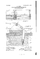
- FIG. 1 represents a portion of the zither equipped with my invention.
- Fig. 2 rep resents a section on the line 2-2 which is very much enlarged to show how the pins are anchored in position by the engagement of their roughened or screwthreaded portions with the walls of the apertures in which they are inserted.
- a indicates the sounding board, across which are strung strings I). I have not illustrated any particular means for hitching the ends of these strings, any suitable means being utilized tor this purpose.
- a bridge which is on a line intermediate oi the ends ol the instrument. This bridge is secured to the sounding board a and to an interior cross-piece d.
- the bridge 0 is illustrated as notched at c for the passage of the melody strings I) which are arranged in a chromatic scale.
- chord strings extend from the bridge 0 to the left end of the instrument (not shown) where they are secured by any suitable means. Said strings c are stretched over a metallic bar f which is supported upon the top of the bridge and their ends are secured to hitch pins 9, to be described.
- the sounding board a and the lower cross-piece d have a plurality of holes or apertures h which are slightly inclined with respect to a line perpendicular to the plane surface of the sounding board. These apertures are bored close to the edge or side oi the bridge 0 so that the lower edge of the bridge is substantially tangential to the mouths of the apertures.
- the hitch pins 9 are preferably lormed of wire and each has a shank g which is threaded, corrugated or roughened as at 5
- the upper end 01' the pin is bent to form a hook g, which projects laterally irom the bridge 0.
- the pins g are a little smaller in diameter than the holes h so that they may be dropped loosely into place and extracted when desired with ease.
- Fig. 2 represents the construction greatly magnified, and it will be seen from this figure that, when the pin is inserted in the aperture and the string 6 is drawn taut by the tuning pin to which it is connected, the pin Will be tilted about the edge of the bridge as a iul crum, so that the threads 9 will be caused to embed themselves in the wall of the aperture whereby the pin will be securely held against outward movement.
- the difference in size oi the pin and its aperture may be exaggerated somewhat in the figure, and the inclination of the pin and the aperture relatively to the perpendicular to the plane of the sounding board may he at a little greater angle than is necessary, but I have practically demonstrated it to be a l'act that, by constructing the pin with a hook and locating it in a slightly enla ged aperture, so that it can swing about the edge of thebridge, the threads become so embedded in the wall of the aperture that there is no danger whatever ot' the pin getting loose.
- the bridge also serves as an abutmentdor the pin to prevent it from bending unduly under hard strain. tor it will be seen that the hook g on the pin is relatively close to the sounding board a, so that the end of the loop on the string is substantially below the top ot the vertical side of the bridge.
- a hitch pin aperture Whose mouth is substantially tangential to the edge of the bridge, and Whose axis is at an inclination to a perpendicular to the surface of the sounding board of the instrument, and a hitch pin having a hooked upper end and a threaded lower end.
Landscapes
- Physics & Mathematics (AREA)
- Engineering & Computer Science (AREA)
- Acoustics & Sound (AREA)
- Multimedia (AREA)
- Stringed Musical Instruments (AREA)
Description
No. 870,283. PATENTED NOV. 5, 1907.
J. R. GREEN.
HITCH PIN FOR STRINGBD INSTRUMENTS.
APPLIOATIO! run In. as. 1907.
6%; {6.5.3 es,- /2 -6 era 2 0? UNITED STATES PATENT OFFICE.
JOSEPH R. GREEN, OF WAKEFIELD, MASSACHUSETTS, ASSIGNOR TO THE PHONOHARP COMPANY, OF EAST BOSTON, MASSACHUSETTS, A CORPORATION OF MAINE.
HITCH-PIN FOR STRINGED INSTRUMENTS.
Specification of Letters Patent.
Patented Nov. 5, 1907.
To all whom it may concern:
Be it known that I, Josnrn R. GREEN, of Wakefield, in the county of Middlesex and State of Massachusetts, have invented certain new and useful Improvements in Hitch-Pins ior Stringed Instruments, of which the following is a specification.
This invention has relation to musical instruments and more particularly to pins for employment in stringed instruments for the attachment of the ends of the strings.
The object of the invention is to provide an improved hitch pin construction by means of which the strings may be held securely without danger of the pin becoming dislocated or yielding under the strain of the strin and yet which will permit the easy insertion or removal of the pin when desired.
On the drawing,-Figure 1 represents a portion of the zither equipped with my invention. Fig. 2 rep resents a section on the line 2-2 which is very much enlarged to show how the pins are anchored in position by the engagement of their roughened or screwthreaded portions with the walls of the apertures in which they are inserted.
While the invention is applicable to a variety of instruments, nevertheless it is best adapted for such instruments as the zither, harp and the like, of which an example is shown upon the drawing.
Referring to the said drawing, a indicates the sounding board, across which are strung strings I). I have not illustrated any particular means for hitching the ends of these strings, any suitable means being utilized tor this purpose.
At 0 there is a bridge which is on a line intermediate oi the ends ol the instrument. This bridge is secured to the sounding board a and to an interior cross-piece d. The bridge 0 is illustrated as notched at c for the passage of the melody strings I) which are arranged in a chromatic scale.
0 indicates what may be termed chord strings. These strings extend from the bridge 0 to the left end of the instrument (not shown) where they are secured by any suitable means. Said strings c are stretched over a metallic bar f which is supported upon the top of the bridge and their ends are secured to hitch pins 9, to be described.
The description thus far (except of the hitch pins) relates to the particular form of instrument which I have selected at illustrating the character of one for which my invention is applicable, and I desire to here have it understood that the invention is not limited to this particular form oi instrument but is capable of embodiment in pianos and various other t'orms ol stringed instruments in which a bridge or analogous cross-piece is located above the plane oi the sounding board.
It will be seen that the sounding board a and the lower cross-piece d have a plurality of holes or apertures h which are slightly inclined with respect to a line perpendicular to the plane surface of the sounding board. These apertures are bored close to the edge or side oi the bridge 0 so that the lower edge of the bridge is substantially tangential to the mouths of the apertures. I
The hitch pins 9 are preferably lormed of wire and each has a shank g which is threaded, corrugated or roughened as at 5 The upper end 01' the pin is bent to form a hook g, which projects laterally irom the bridge 0. The pins g are a little smaller in diameter than the holes h so that they may be dropped loosely into place and extracted when desired with ease.
Fig. 2 represents the construction greatly magnified, and it will be seen from this figure that, when the pin is inserted in the aperture and the string 6 is drawn taut by the tuning pin to which it is connected, the pin Will be tilted about the edge of the bridge as a iul crum, so that the threads 9 will be caused to embed themselves in the wall of the aperture whereby the pin will be securely held against outward movement.
The difference in size oi the pin and its aperture may be exaggerated somewhat in the figure, and the inclination of the pin and the aperture relatively to the perpendicular to the plane of the sounding board may he at a little greater angle than is necessary, but I have practically demonstrated it to be a l'act that, by constructing the pin with a hook and locating it in a slightly enla ged aperture, so that it can swing about the edge of thebridge, the threads become so embedded in the wall of the aperture that there is no danger whatever ot' the pin getting loose. The bridge also serves as an abutmentdor the pin to prevent it from bending unduly under hard strain. tor it will be seen that the hook g on the pin is relatively close to the sounding board a, so that the end of the loop on the string is substantially below the top ot the vertical side of the bridge.
Having thus explained the nature of the invention and described a way ot constructing and using the same, although without attempting to settorth all of 10 a hitch pin aperture Whose mouth is substantially tangential to the edge of the bridge, and Whose axis is at an inclination to a perpendicular to the surface of the sounding board of the instrument, and a hitch pin having a hooked upper end and a threaded lower end.
In testimony whereof I have aflixed my signature, in presence of two witnesses.
JOSEPH R. GREEN.
Witnesses:
C. F. BROWN, A. L. FoLsoM.
Priority Applications (1)
| Application Number | Priority Date | Filing Date | Title |
|---|---|---|---|
| US35438407A US870283A (en) | 1907-01-28 | 1907-01-28 | Hitch-pin for stringed instruments. |
Applications Claiming Priority (1)
| Application Number | Priority Date | Filing Date | Title |
|---|---|---|---|
| US35438407A US870283A (en) | 1907-01-28 | 1907-01-28 | Hitch-pin for stringed instruments. |
Publications (1)
| Publication Number | Publication Date |
|---|---|
| US870283A true US870283A (en) | 1907-11-05 |
Family
ID=2938730
Family Applications (1)
| Application Number | Title | Priority Date | Filing Date |
|---|---|---|---|
| US35438407A Expired - Lifetime US870283A (en) | 1907-01-28 | 1907-01-28 | Hitch-pin for stringed instruments. |
Country Status (1)
| Country | Link |
|---|---|
| US (1) | US870283A (en) |
Cited By (2)
| Publication number | Priority date | Publication date | Assignee | Title |
|---|---|---|---|---|
| US5092213A (en) * | 1987-04-20 | 1992-03-03 | Cipriani Thomas P | Guitar saddle having an inclined lever portion |
| US5410936A (en) * | 1993-05-27 | 1995-05-02 | The 2Tek Corporation | Musical instrument bridge |
-
1907
- 1907-01-28 US US35438407A patent/US870283A/en not_active Expired - Lifetime
Cited By (3)
| Publication number | Priority date | Publication date | Assignee | Title |
|---|---|---|---|---|
| US5092213A (en) * | 1987-04-20 | 1992-03-03 | Cipriani Thomas P | Guitar saddle having an inclined lever portion |
| US5410936A (en) * | 1993-05-27 | 1995-05-02 | The 2Tek Corporation | Musical instrument bridge |
| US5503054A (en) * | 1993-05-27 | 1996-04-02 | 2Tek Corporation | Musical instrument bridge |
Similar Documents
| Publication | Publication Date | Title |
|---|---|---|
| US870283A (en) | Hitch-pin for stringed instruments. | |
| US964660A (en) | Stringed musical instrument. | |
| US572677A (en) | George goodwin | |
| US1290177A (en) | Stringed musical instrument. | |
| US663187A (en) | Tone-finder for stringed musical instruments. | |
| US1170999A (en) | Bridge for stringed instruments. | |
| US336428A (en) | Violin tajl-piece | |
| US475674A (en) | Charles j | |
| US818289A (en) | Stringed musical instrument. | |
| US617915A (en) | Tailpiece for stringed musical instruments | |
| US490213A (en) | Combined bridge and tail-piece for musical instruments | |
| US1230695A (en) | Guitar-bridge. | |
| US796289A (en) | Tuning device for musical instruments. | |
| US213345A (en) | Improvement in tail-pieces for violins | |
| US688272A (en) | Bridge for stringed instruments. | |
| US550366A (en) | Tuning-pin and adjusting-screw for pianos | |
| US591472A (en) | Charles f | |
| US462869A (en) | Charles e | |
| US509240A (en) | William p | |
| US351406A (en) | Steing holder foe musical instruments | |
| US402118A (en) | white | |
| US495823A (en) | Banjo | |
| US1264140A (en) | Bushing for piano tuning-pins. | |
| US555651A (en) | Musical instrument | |
| US833517A (en) | Banjo. |