US8701552B2 - Forming device for articles of food - Google Patents
Forming device for articles of food Download PDFInfo
- Publication number
- US8701552B2 US8701552B2 US12/608,354 US60835409A US8701552B2 US 8701552 B2 US8701552 B2 US 8701552B2 US 60835409 A US60835409 A US 60835409A US 8701552 B2 US8701552 B2 US 8701552B2
- Authority
- US
- United States
- Prior art keywords
- press mechanism
- shell
- press
- assembly
- forming device
- Prior art date
- Legal status (The legal status is an assumption and is not a legal conclusion. Google has not performed a legal analysis and makes no representation as to the accuracy of the status listed.)
- Active - Reinstated, expires
Links
Images


Classifications
-
- A—HUMAN NECESSITIES
- A47—FURNITURE; DOMESTIC ARTICLES OR APPLIANCES; COFFEE MILLS; SPICE MILLS; SUCTION CLEANERS IN GENERAL
- A47J—KITCHEN EQUIPMENT; COFFEE MILLS; SPICE MILLS; APPARATUS FOR MAKING BEVERAGES
- A47J43/00—Implements for preparing or holding food, not provided for in other groups of this subclass
- A47J43/20—Shapes for preparing foodstuffs, e.g. meat-patty moulding devices, pudding moulds
-
- A—HUMAN NECESSITIES
- A23—FOODS OR FOODSTUFFS; TREATMENT THEREOF, NOT COVERED BY OTHER CLASSES
- A23P—SHAPING OR WORKING OF FOODSTUFFS, NOT FULLY COVERED BY A SINGLE OTHER SUBCLASS
- A23P20/00—Coating of foodstuffs; Coatings therefor; Making laminated, multi-layered, stuffed or hollow foodstuffs
- A23P20/20—Making of laminated, multi-layered, stuffed or hollow foodstuffs, e.g. by wrapping in preformed edible dough sheets or in edible food containers
- A23P20/25—Filling or stuffing cored food pieces, e.g. combined with coring or making cavities
Definitions
- the present invention relates to methods and devices for forming, and more specifically molding, articles of food.
- Articles of food are often cooked with a bare minimum of molding for shaping an exterior portion of the food.
- Such molding can include molding through the use of hands.
- Other molding can be achieved through molded cooking devices configured to mold the food prior or during cooking.
- Still other molding can be achieved through the use of utensils or devices configured for molding. While these methods and devices have provided some level of molding for articles of food, they are often limited to specific food types due to varying material consistency of the food or customary shape of the food. Also, many of these molds comprise nothing more than receptacles to be used during cooking.
- a forming device for forming food articles is provided.
- the forming device is configured for not only shaping exterior portions of food, but also interior portions of the food article.
- the forming device is configured for forming a cavity for placement of additional ingredients into the resulting food article.
- additional ingredients may include any ingredient capable of fitting within the cavity formed by the device.
- the forming device is particularly suited for forming hamburgers having a cavity formed therein for receiving one or more food articles commonly associated with a hamburger. After cooking, the hamburger is simply placed between two opposing buns and consumed without necessary additional fixings, ingredients, toppings or otherwise.
- the present invention provides a forming device for articles of food.
- the forming device includes a shell assembly extending between a first end and a second end.
- the shell assembly includes a first shell member disposed at the first end of the shell assembly.
- the first shell member has an annular wall with an inner circumference and an inwardly extending lip.
- the shell assembly also includes a second shell member disposed at the second end of the shell assembly.
- the second shell member has an annular wall with an inner circumference and an inwardly extending lip.
- the forming device further includes a base member disposed proximate to the second end.
- the forming device includes a press assembly moveable between the first end and second end of the shell assembly.
- the press assembly includes a first press mechanism having an outer circumference and an inner circumference.
- the outer circumference of the first press mechanism corresponds generally to the inner circumference of the first or second shell member.
- the press assembly also includes a second press mechanism having an outer circumference generally corresponding to the inner circumference of the first press mechanism.
- the present invention provides a forming device for articles of food.
- the forming device includes a shell assembly extending between a first end and a second end.
- the shell assembly includes a first shell member disposed at the first end.
- the first shell member has an annular wall with an inner circumference and a inwardly extending lip.
- the shell assembly also includes a second shell member disposed at the second end.
- the second shell member has an annular wall with an inner circumference and an inwardly extending lip.
- the shell assembly further includes a base member disposed proximate to the second end of the shell assembly.
- the base member is supported by the inwardly extending lip of the second shell member.
- the shell assembly still further includes a hinge rotatably connecting the first shell member to the second shell member.
- the hinge is configured to allow rotation of the first shell member with respect to the second shell member to allow the forming device to move between an open position and a closed position for receiving articles of food.
- the forming device further includes a press assembly moveable between the first end and second end of the shell assembly.
- the press assembly includes a first press mechanism having an outer circumference and an inner circumference.
- the outer circumference of the first press mechanism corresponds generally to the inner circumference of the first and second shell member.
- the press assembly also includes a second press mechanism having an outer circumference generally corresponding to the inner circumference of the first press mechanism.
- the press assembly further includes a handle having two opposing engagement features for selective engagement with the first press mechanism and the second press mechanism.
- the handle is configured to cause movement of the first and second press mechanism between the first end and second end of the shell assembly.
- the engagement features are engaged with the first and second press mechanisms and the first and second press mechanisms are moveable between the first and second end of the shell assembly.
- the engagement features are engaged with only the second press mechanism and the second press mechanism is moveable between the first and second end of the shell assembly and independent of the first press mechanism.
- the engagement features are engaged with the first and second press mechanisms and the first and second press mechanisms are substantially prevented from moving between the first and second end of the shell assembly.
- FIG. 1 illustrates a perspective view of an exemplary forming device for articles of food according to the teachings of the present invention
- FIG. 2 illustrates an exploded perspective view of the forming device shown in FIG. 1 ;
- FIG. 3 illustrates a perspective view of the forming device shown in FIG. 1 in a first position
- FIG. 4 illustrates a perspective view of the forming device shown in FIG. 1 in a second position
- FIG. 5 illustrates a perspective view of the forming device shown in FIG. 1 in a third position
- FIG. 6 illustrates a perspective view of the forming device shown in FIG. 1 in a fourth position
- FIG. 7 illustrates a perspective view of the forming device shown in FIG. 1 in a fifth position
- FIG. 8 illustrates a cross-sectional view of the forming device taken along line 8 - 8 of FIG. 3 ;
- FIG. 9 illustrates a cross-sectional view of the forming device taken along line 9 - 9 of FIG. 4 ;
- FIG. 10 illustrates a cross-sectional view of the forming device taken along line 10 - 10 of FIG. 5 ;
- FIG. 11 illustrates a cross-sectional view of the forming device taken along line 11 - 11 of FIG. 6 ;
- FIG. 12 illustrates a cross-sectional view of the forming device taken along line 12 - 12 of FIG. 7 ;
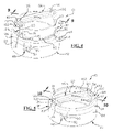
- FIG. 13 illustrates a perspective view of a formed food article according to the teachings of the present invention.
- FIG. 14 illustrates a cross-sectional view of the formed food article shown in FIG. 13 .
- the present invention relates to methods and devices for forming articles of food.
- the methods and devices are configured for forming exterior portions and interior portions of a food article so as to form a cavity for placement of similar or different articles of food therein.
- the present invention provides a forming device configured.
- the forming device is configured to form an exterior portion of the food article in a first step, an interior portion of the food article in a second step and an interior and exterior portion in a third step.
- the forming device is suited for forming articles, particularly food articles, having cavities for receiving similar or different food articles.
- the forming device is particularly suited for forming hamburgers.
- the forming device is configured for forming a lower layer having a recessed portion for placement of any ingredient desired within a hamburger, such as condiments, pickles, onions, cheese, spices, tomatoes, lettuce, other vegetables, meats, or otherwise.
- the forming device is further configured for forming an upper layer and pressing the upper layer and lower layer together to form a unitary hamburger structure having a cavity.
- the forming device provides the ability to form a multi-layered stuffed hamburger, wherein, the added ingredients are sealed within the hamburger until consumed.
- the forming device 10 is configured for forming articles, particularly food articles 12 , having a cavity 14 formed therein, for receiving one or more additional food articles 16 , as shown in FIGS. 13 and 14 .
- the forming device 10 includes a shell 18 extending between a first end 20 and a second end 22 .
- the shell 18 is configured to move between an open position and a closed position.
- the shell 18 includes a first shell member 24 and a second shell member 26 .
- the first shell member 24 includes an annular wall 28 defining an inner circumference 30 and an inwardly extending lip 32 disposed at the first end 20 of the shell 18 .
- the second shell member 26 also includes an annular wall 34 defining an inner circumference 36 and inwardly extending lip 38 disposed at the second end 22 of the shell 18 .
- annular walls 28 , 34 may be circular, oval, square, rectangular, triangular or may comprise any other suitable or desired shape.
- the first and second shell members 24 , 26 are attached together through a hinge 40 comprising a first hinge member 42 associated with the first shell member 26 and a second hinge member 44 associated with the second shell member 26 .
- the first and second hinge members 42 , 44 are rotatably attached to one another through a pin 46 .
- the shell further includes a latch 48 for maintaining the first and second shell members 24 , 26 together during the closed position of the shell 18 .
- the latch 48 includes a first latch member 50 associated with the first shell member 24 and a second latch member 52 associated with the second shell member 26 .
- the first and second latch members 50 , 52 form a snap-fitting.
- the forming device 10 further includes a base 54 disposed at the second end 22 of the shell 18 to provide support to the food article 12 .
- the base 54 is supported by the inwardly extending lip 38 of the second shell member 26 .
- the base 54 may be integrally formed with the second shell member 26 .
- the forming device 10 further includes a press assembly 56 moveable between the first end 20 and the second end 22 of the shell 18 and rotatably moveable with respect to the shell 18 .
- the press assembly 56 includes a first press mechanism 58 and a second press mechanism 60 .
- the first and second press mechanisms 58 , 60 are configured to move between the first and second end 22 , 24 of the shell 18 either in unison or independently depending on the position of the press assembly 56 .
- the first and second press mechanisms 58 , 60 are further configured for rotatable movement in unison with respect to the shell 18 .
- the first press mechanism 58 includes a base 62 defining an outer circumference 64 generally corresponding to the inner circumferences 30 , 36 of the first and second shell members 24 , 26 , respectively.
- a seal is formed between the outer circumference 64 of the first press mechanism 58 and the inner circumference 30 , 36 of annular walls 28 , 34 of the first and second shell members 24 , 26 .
- an elastic seal member is disposed between the second press mechanism 60 and the first and/or second shell member 24 , 26 .
- the base 62 of the first press mechanism 58 forms an opening 66 defined by an inner circumference 68 .
- the base 62 is formed of a first outwardly extending ring 70 and a second upwardly extending ring 72 , which is generally perpendicular to the outwardly extending ring 70 .
- the first press mechanism 58 further includes an engagement feature 74 for engagement with the second press mechanism 60 .
- the engagement feature is formed on two opposing extensions 76 extending generally perpendicular with respect to the outwardly extending ring 70 .
- the engagement feature 74 includes a slot 78 extending generally perpendicular with respect to the outwardly extending ring 70 .
- the slots 78 are configured for receiving engagement members 80 .
- the slots 78 extend generally vertical from a first end of the extensions 76 and perpendicular at a second end of the extensions 76 , with respect to base 62 .
- the engagement feature 78 includes locking features 82 disposed with each engagement feature 74 for maintaining the position of the engagement member 80 with respect to the first press mechanism 58 .
- the locking feature 82 comprises a resilient member 84 and a tab 86 disposed along the perpendicular portion of slot 78 .
- the second press mechanism 60 includes a base 88 and a vertically extending annular wall 90 having an outer circumference 92 corresponding generally to the inner circumference 68 of the first press mechanism 58 to allow the second press mechanism to move within the opening 66 formed by the first press mechanism 58 .
- the annular wall 90 of the second press mechanism 60 and inner circumference 68 of the first press mechanism 58 may be circular, oval, square, rectangular, triangular or may comprise any other suitable or desired shape.
- a seal may be formed or provided between annular wall 90 of the second press mechanism 60 and the inner circumference 68 of the first press mechanism 58 .
- the second press mechanism 60 includes two opposing engagement features 94 for engagement with the first press mechanism 58 and more specifically engagement members 80 .
- the engagement features 94 are formed on two opposing extensions 96 extending from the base 88 and annular wall 90 .
- Each engagement feature 94 includes a recessed portion 98 configured for receiving the engagement members 80 .
- the engagement feature 94 of the second press mechanism 60 further includes a two opposing tabs 100 for releasable engagement with the engagement member 80 .
- the forming device 10 further includes a handle 102 for causing movement of the first press mechanism 58 and the second press mechanism 60 .
- a first end 104 and a second end 106 of the handle 102 includes engagement members 80 for engagement with the first and second press mechanisms 58 , 60 .
- the forming device further includes a post extending between the handle 102 and second press mechanism 60 , or other device or member, for increasing rigidity of the handle and/or forming device.
- the forming device 10 is configured for movement between multiple positions for forming a food article 12 , as described herein.
- a first position referring to FIGS. 3 and 8 , the forming device 10 is in an initial position and configured to move between an open and a closed position for receiving a food article 12 into a cavity 108 formed by the second shell member 26 .
- the press assembly 56 is rotated, counterclockwise, into a lock position, which resists further rotational movement of the press assembly 56 .
- the lock position is achieved through a rotational lock mechanism 110 formed between the first press mechanism 58 and the inwardly extending lip 32 of the first shell member 24 .
- the lock mechanism 110 comprises a first tab 112 formed on the press assembly 56 and disposed between two adjacently located tabs 114 formed on the inwardly extending lip 32 of the first shell member 24 .
- the press assembly 56 is further prevented from movement between the first and second ends of the shell 18 by an engagement between the inwardly extending lip 32 of the first shell member 24 and a groove 116 formed in the extension 76 of the first press mechanism 58 .
- the engagement of the inwardly extending lip 32 and groove 116 provides rotational guidance of the press assembly 56 about the shell 18 .
- the forming device 10 In a second position, the forming device 10 , shown in FIG. 3 , is opened to expose the cavity 108 formed by the second shell member. This is achieved by unlatching latch 48 to allow the first shell member 24 to move, along with the press assembly 56 , with respect to the second shell member 26 , via hinge 40 .
- a food article 12 such as a hamburger, the like or otherwise, is placed in cavity 108 , which is supported by the second shell member 24 , via base 54 .
- the forming device 10 is closed, via the hinge 40 , and locked, via the latch 48 .
- a third position referring to FIGS. 4 and 9 , the press assembly 56 is rotated into a compress position to compress the food article 12 within cavity 108 .
- the press assembly 56 is rotated clockwise, which is guided by groove 116 and inwardly extending lip 32 , until the extensions 76 of the first press mechanism 58 are aligned with slots or openings 118 formed through the inwardly extending lip 32 .
- Rotation stops 120 are formed by edges 122 of extensions 76 and edges 124 forming openings 118 , which also provide alignment of extensions 76 with openings 118 .
- groove 116 is no longer engaged with inwardly extending lip 32 , which allows movement of the press assembly 56 between the first and second ends 20 , 22 of the shell 18 .
- the press assembly 56 including the first and second press mechanism 58 , 60 , are lowered to the second end 22 of shell 18 to compress the food article 12 within cavity 108 .
- the amount of movement of the press assembly 56 is dependent upon the volume of food article 12 placed within cavity 108 .
- the base 62 of the first press mechanism 58 and the base 88 of the second press mechanism 60 compress the food article 12 against base 62 .
- inner circumference 36 of the second shell member 26 shapes an outer circumference of the food article 12 to form a cylindrical shaped food article 12 . It should be appreciated that the distance between base 62 of the first press mechanism 58 and base 62 will vary based upon the volume of food article 12 with cavity 108 .
- the base 62 of the first press mechanism 58 includes a plurality of openings 126 for facilitating in airflow therethrough during movement towards and away from second end 22 of the shell 18 .
- base 54 also includes a plurality of openings 128 for facilitating airflow therethrough, during movement of the press assembly 56 between the first and second end of the shell 18 .
- the airflow provides improved compression and separation of the forming device 10 with the food article 12 .
- the base 62 includes a plurality of ribs 130 or other contour features for providing unique contours to an exterior surface of the food article 12 , such as grill marks or otherwise.
- the base 88 of the second press mechanism 60 may also include ribs or other contour features.
- base 88 may also include a plurality of openings for airflow therethrough.
- the press assembly 56 is again disposed towards the first end of shell 18 and rotated counter-clockwise to a similar position shown in FIG. 3 .
- the engagement member 80 is disengaged with the first press mechanism 58 , but maintains engagement with the second press mechanism 60 .
- This disengagement of the engagement member 80 with the first press mechanism 58 allows for movement of the second press mechanism 60 between the first and second ends 20 , 22 of the shell 18 that is independent from the first press mechanism 58 .
- the second press mechanism 60 is lowered to become disposed proximate to the second end 22 of the shell 18 , thereby causing compression of a central portion of the food article 12 within cavity 108 .
- This central compression creates the cavity 14 of the food article 12 allowing for placement of food articles therein by depressing only the central portion of the food article 12 while the exterior portions maintain position or increase in height due to a gap 132 formed between the annular wall 90 of the second press mechanism 60 and the annular wall 34 of the second shell member 26 .
- the second press mechanism 60 After compression, resulting from the sixth position, the second press mechanism 60 is raised proximate to the first end of the shell 18 and back to the fifth position shown in FIGS. 6 and 11 .
- the engagement members 80 and second press mechanism 60 is then rotated clockwise to reengage the engagement members 80 with the first press mechanism 58 thereby causing engagement of the first and second press mechanism 58 , 60 and movement back to the first position shown in FIG. 3 .
- the forming device 10 is then opened, i.e. the press assembly 56 and first shell member 24 are rotated, with respect to the second shell member 22 , to place additional food articles within cavity 108 .
- the cavity 14 formed in the food article 12 is filled with one or more additional food articles 16 .
- an additional food article 134 similar to that of food article 12 and having a diameter similar to the inner circumference 36 of the second shell member 26 is placed over the food article 12 and additional food article 16 .
- the forming device 10 is then closed and the press assembly 56 is rotated back to the third position, shown in FIGS. 4 and 9 .
- the press assembly 56 i.e. first and second press mechanisms 58 , 60 , are moved toward the second end of the shell 18 to compress the food articles 12 , 16 , 134 together.
- the press assembly is then moved back into the first position, shown in FIGS. 3 and 8 , and the forming device is opened to remove the formed food article 136 for consumption or further processing, such as cooking, seasoning or otherwise.
- the formed food article 136 may be cooked within the forming device 10 .
- FIGS. 13 and 14 an exemplary embodiment of a formed food article 136 , according to the teachings of the present invention, is shown.
- the original food article 12 is placed within the cavity 108 of the second shell member 26 has combined with the additional food article 134 to form the resulting cavity 14 for receiving the additional food article 16 .
- the resulting formed food article may comprise a unitary structure that is capable of being cooked or otherwise further processed without falling apart, due to the compression applied during the forming process.
- the forming device 10 maybe formed of any suitable material capable of withstanding suitable forces for creating the formed food article 136 .
- the components of the forming device 10 are formed of a substantially similar material.
- the forming device is formed of multiple materials, materials having added reinforcement, such as additional components, fillers or otherwise, for providing additional strength for materials undergoing greater forces. Accordingly, it is contemplated that the forming device may be formed of metal, plastic, ceramic, glass or otherwise.
- the forming device is formed of plastic, and more particularly of polypropylene copolymer.
- the forming device 10 is formed of a material resistance to high temperatures such a stainless steel or otherwise for heating the formed food article 130 within the forming device 10 . It should be appreciated that other materials are possible.
- one or more, or even substantially all of the components forming the forming device 10 includes a non-stick surface or reduced stick layer for improving removal of the resulting formed food articles 136 .
- a non-stick surface or reduced stick layer for improving removal of the resulting formed food articles 136 .
- suitable non-stick or reduce stick material includes TeflonTM, though others are possible.
- forming device 10 may include one or more additional features, such as features for increasing rigidity of the forming device 10 during use.
- the forming device includes a reinforcement post extending between the handle 102 and the second press mechanism 60 for increasing compression capabilities during various stages of forming the formed food article 136 .
- the material thickness shown in the drawings may be increased or decreased according the strength requirements, weight, material cost or otherwise.
- the forming device of the present invention may be used to form various food articles that may or may not need further processing such as cooking, seasoning or otherwise. Accordingly, it is contemplated that the food article 12 may comprise beef, pork, chicken, or other meat. It is further contemplated that the food article 12 may comprise non-meat products, such as tofu or otherwise. In either configuration, or otherwise, it should be appreciated that the resulting formed food article 130 may be further proceeded, cooked or otherwise, or may comprise a final product suitable for serving.
Landscapes
- Engineering & Computer Science (AREA)
- Food Science & Technology (AREA)
- Life Sciences & Earth Sciences (AREA)
- Chemical & Material Sciences (AREA)
- Polymers & Plastics (AREA)
- Mechanical Engineering (AREA)
- Food-Manufacturing Devices (AREA)
Abstract
Description
Claims (20)
Priority Applications (1)
| Application Number | Priority Date | Filing Date | Title |
|---|---|---|---|
| US12/608,354 US8701552B2 (en) | 2008-10-30 | 2009-10-29 | Forming device for articles of food |
Applications Claiming Priority (2)
| Application Number | Priority Date | Filing Date | Title |
|---|---|---|---|
| US19770208P | 2008-10-30 | 2008-10-30 | |
| US12/608,354 US8701552B2 (en) | 2008-10-30 | 2009-10-29 | Forming device for articles of food |
Publications (2)
| Publication Number | Publication Date |
|---|---|
| US20100107900A1 US20100107900A1 (en) | 2010-05-06 |
| US8701552B2 true US8701552B2 (en) | 2014-04-22 |
Family
ID=42129880
Family Applications (1)
| Application Number | Title | Priority Date | Filing Date |
|---|---|---|---|
| US12/608,354 Active - Reinstated 2031-09-08 US8701552B2 (en) | 2008-10-30 | 2009-10-29 | Forming device for articles of food |
Country Status (1)
| Country | Link |
|---|---|
| US (1) | US8701552B2 (en) |
Cited By (4)
| Publication number | Priority date | Publication date | Assignee | Title |
|---|---|---|---|---|
| US20150296866A1 (en) * | 2012-11-26 | 2015-10-22 | Maria Nella MELE | Mould for making stuffed or filled food products, in particular sicilian arancini |
| USD844394S1 (en) | 2018-03-29 | 2019-04-02 | Kraft Foods Group Brands Llc | Mold |
| US10894342B2 (en) | 2018-03-29 | 2021-01-19 | Kraft Foods Group Brands Llc | System and method for molding comestible building blocks |
| US11412742B2 (en) * | 2017-05-11 | 2022-08-16 | Pbjla Holdings, Llc | Sandwiching device |
Families Citing this family (14)
| Publication number | Priority date | Publication date | Assignee | Title |
|---|---|---|---|---|
| US7967588B2 (en) * | 2007-11-20 | 2011-06-28 | Clarcor Inc. | Fine fiber electro-spinning equipment, filter media systems and methods |
| US20120269938A1 (en) * | 2011-04-20 | 2012-10-25 | Davison Iii George Mcconnell | Patty-forming tool and method for forming stuffed patties |
| US8506283B1 (en) | 2012-03-06 | 2013-08-13 | Edward Ray Gonzales | Tamale maker |
| USD711695S1 (en) | 2012-09-06 | 2014-08-26 | Aspiring Enterprises Inc. | Press for food |
| US20140065277A1 (en) * | 2012-09-06 | 2014-03-06 | Aspiring Enterprises Inc | Press for making a football shaped pressed food |
| ITRM20130476A1 (en) * | 2013-08-13 | 2015-02-14 | Maria Nella Mele | MOLD FOR THE CONSTRUCTION OF STUFFED OR FILLED FOOD PRODUCTS, IN PARTICULAR SICILIAN ARANCINS |
| USD695577S1 (en) | 2013-02-01 | 2013-12-17 | Atlantic Promotions Inc. | Burger press |
| US9687019B2 (en) | 2013-05-28 | 2017-06-27 | Joseph Imlach | Food press systems, devices, components and methods |
| DE202014103347U1 (en) * | 2014-07-21 | 2015-07-22 | Hans Schüssler | Press for marinating food pieces, especially raw salmon |
| USD770866S1 (en) * | 2014-10-30 | 2016-11-08 | Joshua Bernheim | Hamburger patty forming device |
| USD817119S1 (en) * | 2015-10-08 | 2018-05-08 | Columbia Insurance Company | Burger press |
| US10357053B2 (en) * | 2017-07-17 | 2019-07-23 | Dart Industries Inc. | Apparatus for preparing a moulded food product |
| USD828120S1 (en) | 2017-07-17 | 2018-09-11 | Dart Industries Inc. | Arancini maker |
| IT201700104657A1 (en) * | 2017-09-25 | 2019-03-25 | Giorgio Assenza | Manually operated system for the production of arancini with characteristics equal to the artisan realization |
Citations (5)
| Publication number | Priority date | Publication date | Assignee | Title |
|---|---|---|---|---|
| US3909881A (en) * | 1974-01-09 | 1975-10-07 | Carlton O Anderson | Apparatus for making a hollow hamburger |
| US5074778A (en) * | 1990-11-08 | 1991-12-24 | Pizza Systems, Inc. | Pizza crust dough forming die assembly |
| US5482665A (en) * | 1994-03-18 | 1996-01-09 | General Motors Corporation | Method/apparatus for making fiber-filled cushion |
| US5876769A (en) * | 1996-08-01 | 1999-03-02 | Dowden; Billy | Heated soap mold device for recycling soap bar remnants |
| US6990892B2 (en) * | 2002-08-28 | 2006-01-31 | Richard Ben Errera | Enhanced food embossing stamper device |
-
2009
- 2009-10-29 US US12/608,354 patent/US8701552B2/en active Active - Reinstated
Patent Citations (5)
| Publication number | Priority date | Publication date | Assignee | Title |
|---|---|---|---|---|
| US3909881A (en) * | 1974-01-09 | 1975-10-07 | Carlton O Anderson | Apparatus for making a hollow hamburger |
| US5074778A (en) * | 1990-11-08 | 1991-12-24 | Pizza Systems, Inc. | Pizza crust dough forming die assembly |
| US5482665A (en) * | 1994-03-18 | 1996-01-09 | General Motors Corporation | Method/apparatus for making fiber-filled cushion |
| US5876769A (en) * | 1996-08-01 | 1999-03-02 | Dowden; Billy | Heated soap mold device for recycling soap bar remnants |
| US6990892B2 (en) * | 2002-08-28 | 2006-01-31 | Richard Ben Errera | Enhanced food embossing stamper device |
Cited By (6)
| Publication number | Priority date | Publication date | Assignee | Title |
|---|---|---|---|---|
| US20150296866A1 (en) * | 2012-11-26 | 2015-10-22 | Maria Nella MELE | Mould for making stuffed or filled food products, in particular sicilian arancini |
| US9642393B2 (en) * | 2012-11-26 | 2017-05-09 | Maria Nella MELE | Mould for making stuffed or filled food products, in particular sicilian arancini |
| US11412742B2 (en) * | 2017-05-11 | 2022-08-16 | Pbjla Holdings, Llc | Sandwiching device |
| USD844394S1 (en) | 2018-03-29 | 2019-04-02 | Kraft Foods Group Brands Llc | Mold |
| USD869250S1 (en) | 2018-03-29 | 2019-12-10 | Kraft Foods Group Brands Llc | Mold |
| US10894342B2 (en) | 2018-03-29 | 2021-01-19 | Kraft Foods Group Brands Llc | System and method for molding comestible building blocks |
Also Published As
| Publication number | Publication date |
|---|---|
| US20100107900A1 (en) | 2010-05-06 |
Similar Documents
| Publication | Publication Date | Title |
|---|---|---|
| US8701552B2 (en) | Forming device for articles of food | |
| US20070181008A1 (en) | Cooking method and apparatus | |
| US5690019A (en) | Bread bun mold | |
| AU2002223493A1 (en) | Packing for use when cooking dough and food items in a microwave oven | |
| US20130161337A1 (en) | Insert liners | |
| US11357360B2 (en) | Multipurpose metallic container for take-away food | |
| US20110111104A1 (en) | Hollowing apparatus for meat patties | |
| US20210198024A1 (en) | Food Products For Multifunction Pressure Cookers | |
| US20100055258A1 (en) | Bread Product | |
| US12043473B1 (en) | Collapsible triangular pizza container | |
| US20060037485A1 (en) | Salad shaker | |
| US7442025B2 (en) | Kitchen implement for food preparation | |
| RU168064U1 (en) | Edible container | |
| KR20140112624A (en) | Manufacturing Method of Rice Ball And A Modeling Mold | |
| CA2597125C (en) | Cooking method and apparatus | |
| US20180325294A1 (en) | Food bowl | |
| JP6077153B1 (en) | Side dish tray | |
| US20230000092A1 (en) | Bread for Hamburgers | |
| US8383176B2 (en) | Han-burger and making method thereof | |
| JP7617619B2 (en) | Food packaging container with inner tray | |
| US12490859B2 (en) | Stuffed waffle utensil | |
| KR200305651Y1 (en) | Bread For Hamburger And Dough Mold For Manufacturing The Same | |
| US20050051542A1 (en) | Microwave meat cooker | |
| KR200309764Y1 (en) | Bread for hamburger and dough mold for manufacturing the same | |
| CA2582835C (en) | Cooking method and apparatus |
Legal Events
| Date | Code | Title | Description |
|---|---|---|---|
| AS | Assignment |
Owner name: WESLEY CORPORATION, MICHIGAN Free format text: ASSIGNMENT OF ASSIGNORS INTEREST;ASSIGNOR:HANSON, DAVID WESLEY;REEL/FRAME:032323/0504 Effective date: 20140227 |
|
| STCF | Information on status: patent grant |
Free format text: PATENTED CASE |
|
| MAFP | Maintenance fee payment |
Free format text: PAYMENT OF MAINTENANCE FEE, 4TH YR, SMALL ENTITY (ORIGINAL EVENT CODE: M2551) Year of fee payment: 4 |
|
| FEPP | Fee payment procedure |
Free format text: MAINTENANCE FEE REMINDER MAILED (ORIGINAL EVENT CODE: REM.); ENTITY STATUS OF PATENT OWNER: SMALL ENTITY |
|
| LAPS | Lapse for failure to pay maintenance fees |
Free format text: PATENT EXPIRED FOR FAILURE TO PAY MAINTENANCE FEES (ORIGINAL EVENT CODE: EXP.); ENTITY STATUS OF PATENT OWNER: SMALL ENTITY |
|
| STCH | Information on status: patent discontinuation |
Free format text: PATENT EXPIRED DUE TO NONPAYMENT OF MAINTENANCE FEES UNDER 37 CFR 1.362 |
|
| PRDP | Patent reinstated due to the acceptance of a late maintenance fee |
Effective date: 20220614 |
|
| FEPP | Fee payment procedure |
Free format text: PETITION RELATED TO MAINTENANCE FEES FILED (ORIGINAL EVENT CODE: PMFP); ENTITY STATUS OF PATENT OWNER: SMALL ENTITY Free format text: PETITION RELATED TO MAINTENANCE FEES GRANTED (ORIGINAL EVENT CODE: PMFG); ENTITY STATUS OF PATENT OWNER: SMALL ENTITY Free format text: SURCHARGE, PETITION TO ACCEPT PYMT AFTER EXP, UNINTENTIONAL. (ORIGINAL EVENT CODE: M2558); ENTITY STATUS OF PATENT OWNER: SMALL ENTITY |
|
| MAFP | Maintenance fee payment |
Free format text: PAYMENT OF MAINTENANCE FEE, 8TH YR, SMALL ENTITY (ORIGINAL EVENT CODE: M2552); ENTITY STATUS OF PATENT OWNER: SMALL ENTITY Year of fee payment: 8 |
|
| STCF | Information on status: patent grant |
Free format text: PATENTED CASE |
|
| FP | Lapsed due to failure to pay maintenance fee |
Effective date: 20220422 |
|
| MAFP | Maintenance fee payment |
Free format text: PAYMENT OF MAINTENANCE FEE, 12TH YR, SMALL ENTITY (ORIGINAL EVENT CODE: M2553); ENTITY STATUS OF PATENT OWNER: SMALL ENTITY Year of fee payment: 12 |