US8699679B2 - System apparatus and method for accessing scheduling information - Google Patents
System apparatus and method for accessing scheduling information Download PDFInfo
- Publication number
- US8699679B2 US8699679B2 US12/798,414 US79841410A US8699679B2 US 8699679 B2 US8699679 B2 US 8699679B2 US 79841410 A US79841410 A US 79841410A US 8699679 B2 US8699679 B2 US 8699679B2
- Authority
- US
- United States
- Prior art keywords
- phone
- user
- information
- processor
- server
- Prior art date
- Legal status (The legal status is an assumption and is not a legal conclusion. Google has not performed a legal analysis and makes no representation as to the accuracy of the status listed.)
- Active, expires
Links
Images


Classifications
-
- G—PHYSICS
- G06—COMPUTING OR CALCULATING; COUNTING
- G06Q—INFORMATION AND COMMUNICATION TECHNOLOGY [ICT] SPECIALLY ADAPTED FOR ADMINISTRATIVE, COMMERCIAL, FINANCIAL, MANAGERIAL OR SUPERVISORY PURPOSES; SYSTEMS OR METHODS SPECIALLY ADAPTED FOR ADMINISTRATIVE, COMMERCIAL, FINANCIAL, MANAGERIAL OR SUPERVISORY PURPOSES, NOT OTHERWISE PROVIDED FOR
- G06Q10/00—Administration; Management
- G06Q10/10—Office automation; Time management
- G06Q10/109—Time management, e.g. calendars, reminders, meetings or time accounting
-
- H—ELECTRICITY
- H04—ELECTRIC COMMUNICATION TECHNIQUE
- H04L—TRANSMISSION OF DIGITAL INFORMATION, e.g. TELEGRAPHIC COMMUNICATION
- H04L51/00—User-to-user messaging in packet-switching networks, transmitted according to store-and-forward or real-time protocols, e.g. e-mail
- H04L51/21—Monitoring or handling of messages
- H04L51/222—Monitoring or handling of messages using geographical location information, e.g. messages transmitted or received in proximity of a certain spot or area
-
- H—ELECTRICITY
- H04—ELECTRIC COMMUNICATION TECHNIQUE
- H04L—TRANSMISSION OF DIGITAL INFORMATION, e.g. TELEGRAPHIC COMMUNICATION
- H04L67/00—Network arrangements or protocols for supporting network services or applications
- H04L67/01—Protocols
- H04L67/02—Protocols based on web technology, e.g. hypertext transfer protocol [HTTP]
-
- H—ELECTRICITY
- H04—ELECTRIC COMMUNICATION TECHNIQUE
- H04L—TRANSMISSION OF DIGITAL INFORMATION, e.g. TELEGRAPHIC COMMUNICATION
- H04L67/00—Network arrangements or protocols for supporting network services or applications
- H04L67/2866—Architectures; Arrangements
- H04L67/30—Profiles
- H04L67/306—User profiles
-
- H—ELECTRICITY
- H04—ELECTRIC COMMUNICATION TECHNIQUE
- H04L—TRANSMISSION OF DIGITAL INFORMATION, e.g. TELEGRAPHIC COMMUNICATION
- H04L67/00—Network arrangements or protocols for supporting network services or applications
- H04L67/50—Network services
- H04L67/56—Provisioning of proxy services
- H04L67/565—Conversion or adaptation of application format or content
-
- H—ELECTRICITY
- H04—ELECTRIC COMMUNICATION TECHNIQUE
- H04M—TELEPHONIC COMMUNICATION
- H04M1/00—Substation equipment, e.g. for use by subscribers
- H04M1/253—Telephone sets using digital voice transmission
- H04M1/2535—Telephone sets using digital voice transmission adapted for voice communication over an Internet Protocol [IP] network
-
- H—ELECTRICITY
- H04—ELECTRIC COMMUNICATION TECHNIQUE
- H04M—TELEPHONIC COMMUNICATION
- H04M3/00—Automatic or semi-automatic exchanges
- H04M3/38—Graded-service arrangements, i.e. some subscribers prevented from establishing certain connections
- H04M3/382—Graded-service arrangements, i.e. some subscribers prevented from establishing certain connections using authorisation codes or passwords
-
- H—ELECTRICITY
- H04—ELECTRIC COMMUNICATION TECHNIQUE
- H04L—TRANSMISSION OF DIGITAL INFORMATION, e.g. TELEGRAPHIC COMMUNICATION
- H04L67/00—Network arrangements or protocols for supporting network services or applications
- H04L67/2866—Architectures; Arrangements
- H04L67/2895—Intermediate processing functionally located close to the data provider application, e.g. reverse proxies
-
- H—ELECTRICITY
- H04—ELECTRIC COMMUNICATION TECHNIQUE
- H04M—TELEPHONIC COMMUNICATION
- H04M2203/00—Aspects of automatic or semi-automatic exchanges
- H04M2203/20—Aspects of automatic or semi-automatic exchanges related to features of supplementary services
- H04M2203/2072—Schedules, e.g. personal calendars
-
- H—ELECTRICITY
- H04—ELECTRIC COMMUNICATION TECHNIQUE
- H04M—TELEPHONIC COMMUNICATION
- H04M3/00—Automatic or semi-automatic exchanges
- H04M3/42—Systems providing special services or facilities to subscribers
- H04M3/42136—Administration or customisation of services
Definitions
- This application generally relates to communications, and more particularly, to accessing scheduling information on a data repository to display on a requesting phone.
- FIG. 1 depicts an exemplary environment in which scheduling information can be distributed in accordance with one aspect of the present application
- FIG. 2 shows a typical IP phone that can display a user's scheduling information in accordance with one aspect of the present application
- FIG. 3A is a flow chart providing exemplary processes for syncing the IP phone with a user's profile in accordance with one aspect of the present application
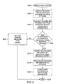
- FIG. 3B illustrates a flow chart that provides exemplary IP phone processes for retrieving and displaying the user's scheduling information in accordance with one aspect of the present application
- FIG. 4A depicts a typical screen on the display of the IP phone used to “Hot Sync” the IP phone in accordance with one aspect of the present application
- FIG. 4B provides an exemplary screen for showing the user's next meeting in accordance with one aspect of the present application
- FIG. 4C illustrates a screen showing exemplary contact information for an attendee in accordance with one aspect of the present application
- FIG. 4D shows an illustrative screen for displaying a user's meetings for the day in accordance with one aspect of the present application
- FIG. 5 represents a flow chart showing exemplary processes for a typical server application in accordance with one aspect of the present application.
- FIG. 6 shows exemplary processes for the message server in accordance with one aspect of the present application.
- the present application relates to communications, and more particularly, to a server application for accessing scheduling information on a message server to display on a requesting phone.
- scheduling information can be obtained using a phone.
- a user can log into a Voice over Internet Protocol (VoIP) phone system by entering their extension number and passcode.
- VoIP Voice over Internet Protocol
- the phone can retrieve the user's profile which the phone can thereafter assume.
- the user's profile can provide a number of features and options for the phone.
- One feature, a “My Next Meeting” feature can be invoked on the phone for retrieving scheduling information from a server application.
- user credentials are provided the first time the user invokes the “My Next Meeting” feature. This can cause the server application on a web server to log into a message server using the user's credentials that are gathered from the phone.
- the server application can extract the scheduling information from the message server and send it on the phone.
- the embodiment described above can provide a convenient tool that allows a user to avoid having to go back to their desk to find out their next meeting. Furthermore, the tool can provide the ability for an individual who does not have a smartphone or personal digital assistant (PDA) to gain access to information on their next scheduled meeting as captured in their PC based calendar application by simply logging into a nearby phone. Generally described, the tool can allow a user to gain access to information on their next scheduled meeting using a network phone.
- PDA personal digital assistant
- the message server provided scheduling information.
- Scheduling information can include, but is not limited to, meetings, appointments, etc.
- This information can include a user's contacts, email addresses, tasks, etc.
- Other data can also be retrieved and will become apparent from the discussion presented below.
- an exemplary environment 100 in which scheduling information can be distributed in accordance with one aspect of the present application is provided.
- a user can retrieve their scheduling information using an IP phone 102 , a server application 104 , and a message server 106 .
- a phone system 120 can be used as well.
- the IP phone 102 , the server application 104 , the message server 106 , and the phone system 120 can be connected to a network 108 .
- the environment 100 illustrated in FIG. 1 is provided for purposes of illustration and should not be construed as the only environment 100 in which the present application can be used in. Fewer or more components can also be used within FIG. 1 .
- the components can include logical connections. These logical connections can be achieved by a communication device coupled to or integral with the IP phone 102 , the server application 104 , the message server 106 , and the phone system 120 .
- the communication devices are not limited to any particular type of communication device.
- the logical connections can be connected to the network 108 , which can take the form of a local area network, wide area network, personal area network, campus area network, metropolitan area network, or global area network.
- Such networking environments are commonplace in office networks, enterprise-wide computer networks, intranets and the Internet, which are all types of networks 108 .
- the communications between the IP phone 102 , the server application 104 , the message server 106 , and the phone system 120 described herein can be implemented as logical operations and/or modules in one or more systems.
- the logical operations can be implemented as a sequence of processor-implemented steps executing in one or more computer systems and as interconnected machine or circuit modules within one or more computer systems.
- the descriptions of various component modules can be provided in terms of operations executed or effected by the modules. The resulting implementation is a matter of choice, dependent on the performance requirements of the underlying system implementing the described technology. Accordingly, the logical operations making up the embodiments described herein can be referred to variously as operations, steps, objects, or modules.
- logical operations can be performed in any order, unless explicitly claimed otherwise or a specific order is inherently necessitated by the claim language.
- IP phone 102 the IP phone 102
- server application 104 the message server 106
- the phone system 120 will be described with the IP phone 102 . Numerous features and functions are provided within the description of each and will become more apparent from the following discussion. From time to time, FIG. 1 will be referred back to when discussing each component of the environment 100 .
- the IP phone 102 can include a graphics display 202 , feature access buttons 204 , and a keypad 206 . While described as primarily working with an IP phone 102 , those skilled in the relevant art will appreciate that other types of phones can be used.
- the graphics display 202 can be a liquid crystal display.
- the display 202 can show text, images, and in some embodiments, moving pictures. Generally, most displays 202 can be provided in color. Touch-screen technologies, known to those skilled in the art, can also be implemented on the display 202 removing the need for feature access buttons 204 , and possibly the keypad 206 .
- the display 202 is typically built to show a large amount of information including scheduling information, emails, contacts, or any other information that can be pulled from of the message server 106 .
- the IP phone 102 can display HyperText Markup Language (HTML) or some other form of markup language such as Extensible Markup Language (XML).
- HTML HyperText Markup Language
- XML Extensible Markup Language
- the IP phone 102 can execute Java applications.
- a browser can be installed or supported by the IP phone 102 to parse and render the HTML or XML.
- button access buttons 204 can be located to the side of the display 202 .
- the buttons 204 can be aligned such that graphics provided on the display 202 can match features associated with those buttons 204 .
- the buttons 204 can implement the specific feature provided on the display 202 .
- the user can press a button 204 that corresponds with a “Hot Desk” feature or a “My Next Meeting” feature.
- Other buttons 204 can be associated with different features, for example, accessing the user's contacts and opening their email from the IP phone 102 .
- the IP phone 102 can include a keypad 206 , which can provide input.
- the input is provided in the form of numerical information.
- the user can enter their extension through the keypad 206 .
- the user can also provide a passcode or password to the phone 102 using the keypad 206 .
- the phone 102 can communicate with the phone system 120 to log the user into the phone 102 .
- the act of logging in causes the phone 102 to assume the user's profile that is stored in the phone system 120 , which can be referred to as a “Hot Desk” feature above.
- the user can provide their extension number (#) and passcode to the phone system 120 .
- the phone system 120 can return the user's profile to the phone 102 .
- the phone 102 can have an HTML based application programming interface (API) that allows an external HTML based application to use the phone's graphical display 202 .
- the API can allow the external HTML application to be notified of button 204 presses on the phone 102 .
- the API can also provide the IP address of the external web application 110 to the phone 102 .
- an XML or Java based phone API supplied by the phone manufacturers can be provided rather than the HTML API.
- the external application can use the phone's display 202 and buttons 204 in the same manner as a PC based web application uses the PC's display and keyboard.
- the external application provided by the server application 104 can provide numerous capabilities to the user of the phone 102 .
- the phone 102 can also provide the server application 104 with the extension # to access scheduling information.
- the extension # can be provided through the API described above, or can be part of a separate channel that interfaces with the server application 104 .
- the phone 102 can have access to other information associated with the user.
- the user's emails can be fed directly into the IP phone 102 .
- the user's contacts can also be provided.
- information that can be provided by the message server 106 can be served and displayed by the phone 102 .
- the user can schedule meetings, change meeting times, or cancel meetings through the phone 102 .
- the feature access buttons 204 along with the keypad 206 can be used to perform a variety of functions.
- a “Hot Desk” feature can be used to log the user into the phone using an extension number and passcode, which will be shown within FIG. 3A .
- This feature can cause the phone to retrieve a user profile from the phone system 120 .
- the IP phone 102 can be used to retrieve a user's scheduling information as depicted in FIG. 3B .
- the user can enter their username and password so that the scheduling information can be obtained from the message server 106 .
- the credentials are stored by the server application 104 , which facilitates communication between the IP phone 102 and the message server 106 . While numerous processes are provided, those skilled in the relevant art will appreciate that fewer or more processes can be used.
- FIG. 3A a flow chart providing exemplary processes for syncing the IP phone 102 with a user's profile in accordance with one aspect of the present application is provided.
- the provided flow chart is one way to “Hot Desk” the IP phone 102 and should not be construed as the only way.
- the processes can begin at block 300 .
- the user can initiate a “Hot Desk” feature shown within FIG. 4A , which depicts a typical screen on the display 202 of the phone 102 .
- the exemplary screen also shows other options that can include a “Phone Book” feature, a “Messaging” Feature, attendees and a “My Next Meeting” feature which will be described below.
- Each of these features can be associated with a feature access button 204 , which is implied in FIG. 4A .
- the phone 102 can request for information from the user so that the phone 102 can be connected with the phone system 120 .
- the user provides their extension number.
- the user can enter in their work number.
- the user can also provide a passcode associated with their extension number.
- the phone 102 can receive user information entered in by the user.
- the phone 102 can then sync with the phone system 120 at block 306 .
- the user provided information can be sent to the phone system 120 and thereafter the phone system 120 can provide user profile information to the phone 102 .
- the phone 102 can receive the user profile.
- the phone By running the user profile on top of the phone 102 , the phone, in essence, acts as a proxy for the user's home computer. Through the “Hot Desk” feature, the user can gain access to the “My Next Meeting” feature, as well as many other features and options, on the phone 102 .
- the processes can end at block 310 .
- FIG. 3B illustrates a flow chart that provides exemplary IP phone 102 processes for retrieving and displaying the user's scheduling information in accordance with one aspect of the present application. The processes can begin at block 318 .
- a button 204 on the phone 102 associated with a “My Next Meeting” option is provided.
- the user can be prompted to enter their message server username and password at block 320 .
- the phone 102 can receive these message server credentials.
- the phone 102 can then make a request to the server application 104 for user scheduling information at block 324 . This can be performed via the API provided by the phone 102 . Initially, the username and password can be sent with the request as well as the extension number. In addition, the phone device ID can be provided. In turn, the server application 104 can log into the message server 106 using the username and password with the message server 106 providing the scheduling information which can then be displayed on the phone 102 that sent the button notification.
- the user provided information can typically be stored on the server application 104 so that the user does not have to enter it again.
- the application 104 can skip having to ask the user for their message server username and password and automatically log the user into the message server 106 without having to ask for the user credentials.
- the user can use any phone to connect to the server application 104 using their extension number.
- the phone 102 can make this determination through error messages received by the server application 104 .
- An error message can arise when no scheduling information is stored within the message server 106 .
- an error message can be provided when a network error occurs.
- the phone 102 can provide a message on the display 202 indicating an error occurred when trying to retrieve the scheduling information at block 328 .
- the error message can provide specific details on why the error occurred, for example, that there was no scheduling information for the user.
- the phone 102 processes can then end at block 330 .
- the information can be displayed at block 332 .
- a separate screen can be shown as depicted in FIG. 4B .
- the date, time, topic, and location can be listed.
- attendees can also be shown.
- the IP phone 102 can be used to contact missing or absent attendees. As shown in FIG. 4B , the attendees are “Don Smith”, “Simon Binder”, “Maureen Young”, and “John Doe”.
- the IP phone 102 can be linked such that it can have direct access to the attendee's office phone or mobile phone so that the missing attendee can be reached. For example, a user of the phone 102 can select “Don Smith”.
- the attendee's information can be shown as depicted in FIG. 4C .
- the information can include, but is not limited to, the attendee's cell phone, work phone, instant message identifier, and email address.
- the phone 102 can reach the attendee at another scheduled meeting typically through a phone located at the meeting site.
- the meeting information for the attendee can be pulled from the message server 106 .
- the meeting information can be displayed on the attendee's phone when called.
- the user can also view the scheduling information for the current day, as depicted in FIG. 4D , by pressing an access button 204 associated with the “View Today” feature.
- Information that can be displayed on the IP phone 102 can include, but is not limited to, the subject, date, start time, duration, and attendees of the meeting.
- the user can call into the server application 104 to retrieve their scheduling information.
- the server application 104 can obtain the user's scheduling information from the message server 106 and provide that information to the IP phone 102 using an automated voice system.
- the phone 102 processes can end at block 330 .
- the user logged into the phone system 120 causing the phone 102 to assume the user's profile.
- the phone 102 could then present the features that they had programmed against their use profile.
- the “My Next Meeting” feature presented above could be one of these features and could allow the user to access their scheduling information on the phone 102 .
- the API would enable the server application 104 to receive button press indications for that button 204 .
- the phone 102 would know who is logged in because of the extension number used to log in.
- the extension number could then be passed to the server application 104 via the phone API so the application could use those credentials to log into the messaging server 106 .
- the server application 104 will now be described in more details.
- the application 104 can run on a server that has a combination of hardware and software designed to retrieve and provide services to the phone 102 and the message server 106 .
- the server can be a private branch exchange (PBX) phone system.
- the server can be a communication service provider.
- PBX private branch exchange
- the server application 104 can run on top of numerous platforms such as Microsoft's Internet Information Server Web Server®, which is depicted in FIG. 1 .
- the server application 104 can include a web application 110 and a web service 112 .
- the web application 110 can serve up the phone interface used to invoke numerous features and display the scheduling information on the user's phone 102 .
- the web service 112 can interface with a data repository contained within the company's message server 106 to extract the user's scheduling information.
- the web service 112 can be programmed to directly interface with Microsoft's Exchange Server®, which is one type of message server.
- the web service 112 can also utilize an API provided by the message server 106 .
- Access to the data stored in the message server 106 can be from across an intranet as well as the Internet, making for a flexible solution from a deployment perspective.
- Security can be maintained through use of individual user credentials provided by the user to gain access to the data stored within the message server 106 . These credentials can be stored by the server application 104 to avoid requiring the user to re-enter them every time they want to use the application.
- the extracted information can be determined by the user through the phone 102 .
- the scheduling information can include information on the current date.
- the extracted information can include the next scheduling entry based on the current time.
- the server application 104 can extract the scheduling information for the following day. If no entries are entered for that day, then the server application 104 can continue to search through the schedule until an entry is found. In other embodiments, the server application 104 can provide an error message or some other indicator that no scheduling information can be found.
- FIG. 5 represents a flow chart showing exemplary processes for a typical server application 104 in accordance with one aspect of the present application.
- the processes can begin at block 500 .
- the server application 104 can receive a request for scheduling information from the phone 102 .
- this can be performed using an API, the API also providing the interface displayed on the phone 102 that the user can enter credentials into. This can occur on the web application 110 side of the server application 104 .
- the server application 104 can request scheduling information from the message server 106 using user credentials. This can occur on the web service 112 side of the server application 104 .
- the web service 112 can use an API generated by the message server 106 to communicate back and forth with the message server 106 .
- the user credentials can include the user's message server username and password, which was entered by the user using the phone dial pad or touch screen keyboard the first time they invoked the “My Next Meeting” feature.
- the user information can be the same as what the user provides to log into their PC.
- the server application 104 can determine whether the scheduling information was received from the message server 106 .
- the message server 106 can return an error message when the message server 106 cannot locate scheduling information for the user.
- an error message can be returned when the user cannot be verified.
- numerous types of errors can occur.
- an error message can be returned to the phone 102 .
- the user can be verified by the server application 104 , instead of the message server 106 .
- the processes for the server application 104 can end at block 510 .
- the scheduling information can be formatted at block 512 . This can occur on the web application 110 .
- the formatting includes changing the information to a markup language, such as XML or HTML, so that the IP phone 102 can parse and render it.
- the server application 104 can provide the scheduling information to the phone 102 .
- the server application 104 can store the user's credentials for future reference.
- the user's credentials can be stored in conjunction with the phone's information so that the user can log in more than one time.
- the credentials can be stored in the server application 104 against the extension number for the user who provided them. By doing this, typically any phone 102 can assume the user's profile.
- the server application 104 can simply look up the user's credentials for that extension number and automatically log them into the message server 106 .
- the information can be stored on the message server 106 or the IP phone 102 .
- the processes for the server application 104 can end at block 510 .
- the message server 106 can locate the user's scheduling information and provide it to a server application 104 .
- Associated with the message server 106 can be a data repository.
- the message server 106 can be deployed by a company that typically stores scheduling data for the user's client calendar application, e.g. Microsoft Outlook®.
- the Microsoft Exchange Server® is a popular message system 106 that can include a mail server, an e-mail client, and groupware applications, the most commonly used being a calendar and contact application. While not dependent on Microsoft Outlook®, the present application can be used to work with Microsoft Outlook®.
- Microsoft Outlook® While not dependent on Microsoft Outlook®, the present application can be used to work with Microsoft Outlook®.
- the message server 106 can provide a web service API that allows a third party application, such as the server application 104 , to gain access to its data.
- the API can be utilized to extract the data to be displayed on the user's IP phone 102 .
- FIG. 6 shows exemplary processes for the message server 106 in accordance with one aspect of the present application.
- the processes can begin at block 600 .
- the message server 106 can receive a scheduling information request from the server application 104 .
- User credentials can be provided by the server application 104 to the message server 106 .
- the message server 106 can determine whether the user is in the system. Typically, this can be determined by the act of logging into the message server 106 using the user credentials. When the login fails, the user is invalid or the credentials provided by the user are incorrect. The message server 106 can also check whether there is any scheduling information. At block 606 , and when no scheduling information can be located for the user or they cannot be verified, the message server 106 can return an error message to the server application 104 . The processes can end at block 608 .
- the scheduling information for the user can be returned by the message server 106 at block 610 .
- the message server 106 can retrieve the scheduling information from the data repository 612 .
- the repository 612 can be updated through a PC based application that is operated from the user's PC.
- the processes can end at block 608 .
- a system in accordance with one aspect of the present application, can include an IP phone displaying a user's profile.
- the user's profile displayed on the IP phone can provide a calendar feature that, when selected, retrieves calendar information from a message server through a server application, the message server storing the calendar information on a central repository.
- the user's profile displayed on the IP phone can be received from a phone system, the phone system verifying an extension number and a passcode received from the IP phone to provide the IP phone with the user's profile.
- a second IP phone can display the user's profile received from the phone system, the second IP phone retrieving the calendar information from the message server through the server application when the calendar feature is selected.
- a username and a password can be stored with an extension number of the IP phone on the server application after an initial login to the message server.
- a phone in accordance with another aspect of the present application, can include an input device, a display, at least one processor, and a memory operatively coupled to the processor, the memory storing program instructions that when executed by the processor, causes the processor to perform processes.
- the processes can include receiving user information from the input device and associating the phone with a profile using the user information.
- the processes can include providing the profile on the display and receiving receive user credentials from the input device.
- the processes can also include accessing scheduling information using the user credentials and providing the scheduling information on the display.
- the user information can include an extension number and a passcode.
- the user credentials can include a username and a password.
- associating the phone with the profile using the user information can include retrieving the profile from a phone system.
- scheduling information can be received in a markup language.
- the memory storing program instructions, when executed by the processor, causes the processor to further receive input from the input device for adjusting the scheduling information.
- adjusting the scheduling information can include cancelling a meeting.
- adjusting the scheduling information can include changing a time for a meeting.
- the memory storing program instructions, when executed by the processor, causes the processor to further receive input from the input device for contacting a meeting attendee.
- a method for providing user data stored within a repository to a network phone synced with a user profile can include receiving user identification information from the network phone synced with the user profile.
- the method can include retrieving the user data stored within the repository using the user identification information.
- the method can also include formatting the user data retrieved from the repository.
- the method can include providing the formatted user data to the network phone synced with the user profile.
- the method can include providing an interface for display on the network phone whereby the user identification information is entered in and the user data is shown. In one embodiment, the method can include storing the user identification information on the server.
- retrieving the user data stored within the repository can include accessing a calendar based application.
- accessing the calendar based application can include extracting user appointments on a date of access.
- accessing the calendar based application can include extracting a next appointment.
- formatting the user data can include setting up the user data within a markup language.
Landscapes
- Engineering & Computer Science (AREA)
- Signal Processing (AREA)
- Business, Economics & Management (AREA)
- Computer Networks & Wireless Communication (AREA)
- Human Resources & Organizations (AREA)
- Entrepreneurship & Innovation (AREA)
- Strategic Management (AREA)
- Marketing (AREA)
- Data Mining & Analysis (AREA)
- Economics (AREA)
- Computer Security & Cryptography (AREA)
- Operations Research (AREA)
- Quality & Reliability (AREA)
- Tourism & Hospitality (AREA)
- Physics & Mathematics (AREA)
- General Business, Economics & Management (AREA)
- General Physics & Mathematics (AREA)
- Theoretical Computer Science (AREA)
- Information Transfer Between Computers (AREA)
- Telephonic Communication Services (AREA)
Abstract
Description
Claims (19)
Priority Applications (3)
| Application Number | Priority Date | Filing Date | Title |
|---|---|---|---|
| US12/798,414 US8699679B2 (en) | 2010-03-31 | 2010-03-31 | System apparatus and method for accessing scheduling information |
| EP11150275A EP2372621A3 (en) | 2010-03-31 | 2011-01-06 | Accessing scheduling information |
| CA2728843A CA2728843C (en) | 2010-03-31 | 2011-01-20 | System, apparatus and method for accessing scheduling information |
Applications Claiming Priority (1)
| Application Number | Priority Date | Filing Date | Title |
|---|---|---|---|
| US12/798,414 US8699679B2 (en) | 2010-03-31 | 2010-03-31 | System apparatus and method for accessing scheduling information |
Publications (2)
| Publication Number | Publication Date |
|---|---|
| US20110243313A1 US20110243313A1 (en) | 2011-10-06 |
| US8699679B2 true US8699679B2 (en) | 2014-04-15 |
Family
ID=44260782
Family Applications (1)
| Application Number | Title | Priority Date | Filing Date |
|---|---|---|---|
| US12/798,414 Active 2031-12-26 US8699679B2 (en) | 2010-03-31 | 2010-03-31 | System apparatus and method for accessing scheduling information |
Country Status (3)
| Country | Link |
|---|---|
| US (1) | US8699679B2 (en) |
| EP (1) | EP2372621A3 (en) |
| CA (1) | CA2728843C (en) |
Families Citing this family (2)
| Publication number | Priority date | Publication date | Assignee | Title |
|---|---|---|---|---|
| US12197932B2 (en) * | 2020-11-09 | 2025-01-14 | Meetings Strategy, Inc. | Method and system for supplementing and providing enhancements to target software data entries |
| JP7477191B2 (en) * | 2022-03-07 | 2024-05-01 | Necプラットフォームズ株式会社 | Server, multifunction telephone, seat reservation system, seat reservation method and program for free address office seat reservation |
Citations (7)
| Publication number | Priority date | Publication date | Assignee | Title |
|---|---|---|---|---|
| US5815566A (en) * | 1991-10-10 | 1998-09-29 | Executone Information Systems, Inc. | Apparatus and method for dynamic inbound/outbound call management and for scheduling appointments |
| US20050119992A1 (en) | 1995-05-19 | 2005-06-02 | Martino Rocco L. | Telephone/transaction entry device and system for entering transaction data into databases |
| US20060159367A1 (en) * | 2005-01-18 | 2006-07-20 | Trestle Corporation | System and method for creating variable quality images of a slide |
| US20070026852A1 (en) | 1996-10-02 | 2007-02-01 | James Logan | Multimedia telephone system |
| US20070115923A1 (en) * | 2005-10-19 | 2007-05-24 | Denny Michael S | Methods, apparatus and computer program products for secondary routing of calls in a voice over internet protocol communication system |
| WO2007123959A2 (en) | 2006-04-20 | 2007-11-01 | Cisco Technology, Inc. | Accessing a calendar server to facilitate initiation of a scheduled call |
| US20100268741A1 (en) * | 2009-04-15 | 2010-10-21 | Creighton University | Calendar system |
-
2010
- 2010-03-31 US US12/798,414 patent/US8699679B2/en active Active
-
2011
- 2011-01-06 EP EP11150275A patent/EP2372621A3/en not_active Ceased
- 2011-01-20 CA CA2728843A patent/CA2728843C/en active Active
Patent Citations (7)
| Publication number | Priority date | Publication date | Assignee | Title |
|---|---|---|---|---|
| US5815566A (en) * | 1991-10-10 | 1998-09-29 | Executone Information Systems, Inc. | Apparatus and method for dynamic inbound/outbound call management and for scheduling appointments |
| US20050119992A1 (en) | 1995-05-19 | 2005-06-02 | Martino Rocco L. | Telephone/transaction entry device and system for entering transaction data into databases |
| US20070026852A1 (en) | 1996-10-02 | 2007-02-01 | James Logan | Multimedia telephone system |
| US20060159367A1 (en) * | 2005-01-18 | 2006-07-20 | Trestle Corporation | System and method for creating variable quality images of a slide |
| US20070115923A1 (en) * | 2005-10-19 | 2007-05-24 | Denny Michael S | Methods, apparatus and computer program products for secondary routing of calls in a voice over internet protocol communication system |
| WO2007123959A2 (en) | 2006-04-20 | 2007-11-01 | Cisco Technology, Inc. | Accessing a calendar server to facilitate initiation of a scheduled call |
| US20100268741A1 (en) * | 2009-04-15 | 2010-10-21 | Creighton University | Calendar system |
Also Published As
| Publication number | Publication date |
|---|---|
| CA2728843A1 (en) | 2011-09-30 |
| EP2372621A3 (en) | 2012-07-25 |
| US20110243313A1 (en) | 2011-10-06 |
| CA2728843C (en) | 2015-12-22 |
| EP2372621A2 (en) | 2011-10-05 |
Similar Documents
| Publication | Publication Date | Title |
|---|---|---|
| US8255923B2 (en) | Shared persistent communication thread | |
| US8463246B2 (en) | Contact management | |
| RU2371876C2 (en) | Common user interface for exchanging messages with registration for each message | |
| US8995769B2 (en) | Method and system of obtaining contact information for a person or an entity | |
| US9473638B1 (en) | Systems and methods for providing access to available agent | |
| US8122088B2 (en) | Adding personal note capabilities to text exchange clients | |
| US8712387B2 (en) | Systems and methods to provide communication history for communication devices | |
| US20060069686A1 (en) | System and method for predicting availability | |
| EP2602976A1 (en) | System facilitating meeting device interactions and methods thereof | |
| US20060075091A1 (en) | System and method for historical presence map | |
| WO2011090822A2 (en) | Automated callback reminder | |
| CN103295121A (en) | Handheld mobile electronic device and method of using electronic calendar therein | |
| US8345839B2 (en) | System and method for providing awareness of and context for phone conversations across multiple personal devices | |
| US9372932B2 (en) | Method for restricting access to data based on current work | |
| GB2556332A (en) | A computerized method and a system for dynamic communication | |
| US8654944B2 (en) | Automated call to a contact with whom another form of communication is exchanged | |
| US8699679B2 (en) | System apparatus and method for accessing scheduling information | |
| KR20110111531A (en) | Methods, devices and computer program products for real-time integration of user-related interactions | |
| US9424559B2 (en) | Annotation of communications | |
| CA2384404A1 (en) | Bar communication | |
| EP1986142A1 (en) | Method and system for modifying a meeting attendee list of an email calendar application | |
| US11244287B2 (en) | Proactively displaying relevant information related to an event on a search page | |
| US10542132B2 (en) | Updating contact details for communications | |
| WO2006038962A1 (en) | System and method for historical presence map | |
| US20150201061A1 (en) | Automatically providing phone numbers viewed on a display screen to a dialing interface of a phone device |
Legal Events
| Date | Code | Title | Description |
|---|---|---|---|
| AS | Assignment |
Owner name: MITEL NETWORKS CORPORATION, CANADA Free format text: ASSIGNMENT OF ASSIGNORS INTEREST;ASSIGNORS:COUSE, PETER FRANCIS;WELLARD, RON;REEL/FRAME:024236/0091 Effective date: 20100329 |
|
| AS | Assignment |
Owner name: BANK OF AMERICA, N.A., AS COLLATERAL AGENT, TEXAS Free format text: SECURITY AGREEMENT;ASSIGNOR:MITEL NETWORKS CORPORATION;REEL/FRAME:030186/0894 Effective date: 20130227 Owner name: WILMINGTON TRUST, N.A., AS SECOND COLLATERAL AGENT Free format text: SECURITY INTEREST;ASSIGNOR:MITEL NETWORKS CORPORATION;REEL/FRAME:030201/0743 Effective date: 20130227 |
|
| AS | Assignment |
Owner name: MITEL US HOLDINGS, INC., ARIZONA Free format text: RELEASE BY SECURED PARTY;ASSIGNOR:WILMINGTON TRUST, NATIONAL ASSOCIATION;REEL/FRAME:032176/0818 Effective date: 20140131 Owner name: MITEL NETWORKS CORPORATION, CANADA Free format text: RELEASE BY SECURED PARTY;ASSIGNOR:WILMINGTON TRUST, NATIONAL ASSOCIATION;REEL/FRAME:032176/0818 Effective date: 20140131 |
|
| AS | Assignment |
Owner name: MITEL US HOLDINGS, INC., ARIZONA Free format text: RELEASE BY SECURED PARTY;ASSIGNOR:BANK OF AMERICA, N.A.;REEL/FRAME:032210/0245 Effective date: 20140131 Owner name: MITEL NETWORKS CORPORATION, CANADA Free format text: RELEASE BY SECURED PARTY;ASSIGNOR:BANK OF AMERICA, N.A.;REEL/FRAME:032210/0245 Effective date: 20140131 |
|
| AS | Assignment |
Owner name: JEFFERIES FINANCE LLC, AS THE COLLATERAL AGENT, NE Free format text: SECURITY AGREEMENT;ASSIGNORS:MITEL US HOLDINGS, INC.;MITEL NETWORKS CORPORATION;AASTRA USA INC.;REEL/FRAME:032264/0760 Effective date: 20140131 Owner name: JEFFERIES FINANCE LLC, AS THE COLLATERAL AGENT, NEW YORK Free format text: SECURITY AGREEMENT;ASSIGNORS:MITEL US HOLDINGS, INC.;MITEL NETWORKS CORPORATION;AASTRA USA INC.;REEL/FRAME:032264/0760 Effective date: 20140131 |
|
| STCF | Information on status: patent grant |
Free format text: PATENTED CASE |
|
| AS | Assignment |
Owner name: MITEL COMMUNICATIONS INC. FKA AASTRA USA INC., TEXAS Free format text: RELEASE BY SECURED PARTY;ASSIGNOR:JEFFERIES FINANCE LLC, AS THE COLLATERAL AGENT;REEL/FRAME:035562/0157 Effective date: 20150429 Owner name: MITEL NETWORKS CORPORATION, CANADA Free format text: RELEASE BY SECURED PARTY;ASSIGNOR:JEFFERIES FINANCE LLC, AS THE COLLATERAL AGENT;REEL/FRAME:035562/0157 Effective date: 20150429 Owner name: MITEL US HOLDINGS, INC., ARIZONA Free format text: RELEASE BY SECURED PARTY;ASSIGNOR:JEFFERIES FINANCE LLC, AS THE COLLATERAL AGENT;REEL/FRAME:035562/0157 Effective date: 20150429 Owner name: MITEL COMMUNICATIONS INC. FKA AASTRA USA INC., TEX Free format text: RELEASE BY SECURED PARTY;ASSIGNOR:JEFFERIES FINANCE LLC, AS THE COLLATERAL AGENT;REEL/FRAME:035562/0157 Effective date: 20150429 |
|
| AS | Assignment |
Owner name: BANK OF AMERICA, N.A.(ACTING THROUGH ITS CANADA BR Free format text: SECURITY INTEREST;ASSIGNOR:MITEL NETWORKS CORPORATION;REEL/FRAME:035783/0540 Effective date: 20150429 |
|
| AS | Assignment |
Owner name: CITIZENS BANK, N.A., MASSACHUSETTS Free format text: SECURITY INTEREST;ASSIGNOR:MITEL NETWORKS CORPORATION;REEL/FRAME:042107/0378 Effective date: 20170309 |
|
| AS | Assignment |
Owner name: MITEL NETWORKS, INC., ARIZONA Free format text: RELEASE BY SECURED PARTY;ASSIGNORS:BANK OF AMERICA, N.A., AS COLLATERAL AGENT;BANK OF AMERICA, N.A., (ACTING THROUGH ITS CANADA BRANCH), AS CANADIAN COLLATERAL AGENT;REEL/FRAME:042244/0461 Effective date: 20170309 Owner name: MITEL BUSINESS SYSTEMS, INC., ARIZONA Free format text: RELEASE BY SECURED PARTY;ASSIGNORS:BANK OF AMERICA, N.A., AS COLLATERAL AGENT;BANK OF AMERICA, N.A., (ACTING THROUGH ITS CANADA BRANCH), AS CANADIAN COLLATERAL AGENT;REEL/FRAME:042244/0461 Effective date: 20170309 Owner name: MITEL COMMUNICATIONS, INC., TEXAS Free format text: RELEASE BY SECURED PARTY;ASSIGNORS:BANK OF AMERICA, N.A., AS COLLATERAL AGENT;BANK OF AMERICA, N.A., (ACTING THROUGH ITS CANADA BRANCH), AS CANADIAN COLLATERAL AGENT;REEL/FRAME:042244/0461 Effective date: 20170309 Owner name: MITEL (DELAWARE), INC., ARIZONA Free format text: RELEASE BY SECURED PARTY;ASSIGNORS:BANK OF AMERICA, N.A., AS COLLATERAL AGENT;BANK OF AMERICA, N.A., (ACTING THROUGH ITS CANADA BRANCH), AS CANADIAN COLLATERAL AGENT;REEL/FRAME:042244/0461 Effective date: 20170309 Owner name: MITEL NETWORKS CORPORATION, CANADA Free format text: RELEASE BY SECURED PARTY;ASSIGNORS:BANK OF AMERICA, N.A., AS COLLATERAL AGENT;BANK OF AMERICA, N.A., (ACTING THROUGH ITS CANADA BRANCH), AS CANADIAN COLLATERAL AGENT;REEL/FRAME:042244/0461 Effective date: 20170309 Owner name: MITEL US HOLDINGS, INC., ARIZONA Free format text: RELEASE BY SECURED PARTY;ASSIGNORS:BANK OF AMERICA, N.A., AS COLLATERAL AGENT;BANK OF AMERICA, N.A., (ACTING THROUGH ITS CANADA BRANCH), AS CANADIAN COLLATERAL AGENT;REEL/FRAME:042244/0461 Effective date: 20170309 |
|
| MAFP | Maintenance fee payment |
Free format text: PAYMENT OF MAINTENANCE FEE, 4TH YEAR, LARGE ENTITY (ORIGINAL EVENT CODE: M1551) Year of fee payment: 4 |
|
| AS | Assignment |
Owner name: MITEL NETWORKS CORPORATION, CANADA Free format text: RELEASE BY SECURED PARTY;ASSIGNOR:CITIZENS BANK, N.A.;REEL/FRAME:048096/0785 Effective date: 20181130 |
|
| AS | Assignment |
Owner name: MITEL NETWORKS ULC, CANADA Free format text: CHANGE OF NAME;ASSIGNOR:MLN ACQUISITIONCO ULC;REEL/FRAME:047694/0607 Effective date: 20181130 Owner name: MITEL CLOUD SERVICES, INC., ARIZONA Free format text: ASSIGNMENT OF ASSIGNORS INTEREST;ASSIGNOR:MITEL NETWORKS ULC;REEL/FRAME:047694/0721 Effective date: 20181205 Owner name: MLN ACQUISITIONCO ULC, CANADA Free format text: MERGER AND CHANGE OF NAME;ASSIGNORS:MITEL NETWORKS CORPORATION;MLN ACQUISITIONCO ULC;REEL/FRAME:047734/0714 Effective date: 20181130 |
|
| AS | Assignment |
Owner name: CREDIT SUISSE AG, CAYMAN ISLANDS BRANCH, AS COLLATERAL AGENT, NEW YORK Free format text: SECURITY INTEREST;ASSIGNOR:MITEL CLOUD SERVICES, INC.;REEL/FRAME:047772/0330 Effective date: 20181207 Owner name: CREDIT SUISSE AG, CAYMAN ISLANDS BRANCH, AS COLLATERAL AGENT, NEW YORK Free format text: SECURITY INTEREST;ASSIGNOR:MITEL CLOUD SERVICES, INC.;REEL/FRAME:047772/0355 Effective date: 20181207 Owner name: CREDIT SUISSE AG, CAYMAN ISLANDS BRANCH, AS COLLAT Free format text: SECURITY INTEREST;ASSIGNOR:MITEL CLOUD SERVICES, INC.;REEL/FRAME:047772/0330 Effective date: 20181207 Owner name: CREDIT SUISSE AG, CAYMAN ISLANDS BRANCH, AS COLLAT Free format text: SECURITY INTEREST;ASSIGNOR:MITEL CLOUD SERVICES, INC.;REEL/FRAME:047772/0355 Effective date: 20181207 |
|
| MAFP | Maintenance fee payment |
Free format text: PAYMENT OF MAINTENANCE FEE, 8TH YEAR, LARGE ENTITY (ORIGINAL EVENT CODE: M1552); ENTITY STATUS OF PATENT OWNER: LARGE ENTITY Year of fee payment: 8 |
|
| AS | Assignment |
Owner name: MITEL CLOUD SERVICES, INC., ARIZONA Free format text: RELEASE BY SECURED PARTY;ASSIGNOR:CREDIT SUISSE AG, CAYMAN ISLANDS BRANCH, AS COLLATERAL AGENT;REEL/FRAME:058698/0085 Effective date: 20220113 Owner name: MITEL CLOUD SERVICES, INC., ARIZONA Free format text: RELEASE BY SECURED PARTY;ASSIGNOR:CREDIT SUISSE AG, CAYMAN ISLANDS BRANCH, AS COLLATERAL AGENT;REEL/FRAME:058698/0162 Effective date: 20220113 Owner name: MITEL CLOUD SERVICES, INC., ARIZONA Free format text: RELEASE OF SECURITY INTEREST;ASSIGNOR:CREDIT SUISSE AG, CAYMAN ISLANDS BRANCH, AS COLLATERAL AGENT;REEL/FRAME:058698/0162 Effective date: 20220113 Owner name: MITEL CLOUD SERVICES, INC., ARIZONA Free format text: RELEASE OF SECURITY INTEREST;ASSIGNOR:CREDIT SUISSE AG, CAYMAN ISLANDS BRANCH, AS COLLATERAL AGENT;REEL/FRAME:058698/0085 Effective date: 20220113 |
|
| AS | Assignment |
Owner name: RINGCENTRAL, INC., CALIFORNIA Free format text: ASSIGNMENT OF ASSIGNORS INTEREST;ASSIGNOR:MITEL CLOUD SERVICES, INC.;REEL/FRAME:058900/0703 Effective date: 20220128 |
|
| AS | Assignment |
Owner name: BANK OF AMERICA, N.A., AS COLLATERAL AGENT, NORTH CAROLINA Free format text: SECURITY INTEREST;ASSIGNOR:RINGCENTRAL, INC.;REEL/FRAME:062973/0194 Effective date: 20230214 |
|
| AS | Assignment |
Owner name: MITEL (DELAWARE), INC., ARIZONA Free format text: RELEASE OF SECURITY INTEREST;ASSIGNOR:ANKURA TRUST COMPANY, LLC;REEL/FRAME:071722/0721 Effective date: 20250620 Owner name: MITEL COMMUNICATIONS, INC., ARIZONA Free format text: RELEASE OF SECURITY INTEREST;ASSIGNOR:ANKURA TRUST COMPANY, LLC;REEL/FRAME:071722/0721 Effective date: 20250620 Owner name: MITEL CLOUD SERVICES, INC., ARIZONA Free format text: RELEASE OF SECURITY INTEREST;ASSIGNOR:ANKURA TRUST COMPANY, LLC;REEL/FRAME:071722/0721 Effective date: 20250620 Owner name: MITEL NETWORKS, INC., ARIZONA Free format text: RELEASE OF SECURITY INTEREST;ASSIGNOR:ANKURA TRUST COMPANY, LLC;REEL/FRAME:071722/0721 Effective date: 20250620 Owner name: MITEL NETWORKS CORPORATION, ARIZONA Free format text: RELEASE OF SECURITY INTEREST;ASSIGNOR:ANKURA TRUST COMPANY, LLC;REEL/FRAME:071722/0721 Effective date: 20250620 Owner name: MITEL (DELAWARE), INC., ARIZONA Free format text: RELEASE BY SECURED PARTY;ASSIGNOR:ANKURA TRUST COMPANY, LLC;REEL/FRAME:071722/0721 Effective date: 20250620 Owner name: MITEL COMMUNICATIONS, INC., ARIZONA Free format text: RELEASE BY SECURED PARTY;ASSIGNOR:ANKURA TRUST COMPANY, LLC;REEL/FRAME:071722/0721 Effective date: 20250620 Owner name: MITEL CLOUD SERVICES, INC., ARIZONA Free format text: RELEASE BY SECURED PARTY;ASSIGNOR:ANKURA TRUST COMPANY, LLC;REEL/FRAME:071722/0721 Effective date: 20250620 Owner name: MITEL NETWORKS, INC., ARIZONA Free format text: RELEASE BY SECURED PARTY;ASSIGNOR:ANKURA TRUST COMPANY, LLC;REEL/FRAME:071722/0721 Effective date: 20250620 Owner name: MITEL NETWORKS CORPORATION, ARIZONA Free format text: RELEASE BY SECURED PARTY;ASSIGNOR:ANKURA TRUST COMPANY, LLC;REEL/FRAME:071722/0721 Effective date: 20250620 |
|
| MAFP | Maintenance fee payment |
Free format text: PAYMENT OF MAINTENANCE FEE, 12TH YEAR, LARGE ENTITY (ORIGINAL EVENT CODE: M1553); ENTITY STATUS OF PATENT OWNER: LARGE ENTITY Year of fee payment: 12 |