US8699237B2 - Soft-switching inverter utilizing high step up ratio circuit with active clamping - Google Patents

Soft-switching inverter utilizing high step up ratio circuit with active clamping Download PDF

Info

Publication number
US8699237B2
US8699237B2 US13/483,102 US201213483102A US8699237B2 US 8699237 B2 US8699237 B2 US 8699237B2 US 201213483102 A US201213483102 A US 201213483102A US 8699237 B2 US8699237 B2 US 8699237B2
Authority
US
United States
Prior art keywords
switch
voltage
capacitor
grid
soft
Prior art date
Legal status (The legal status is an assumption and is not a legal conclusion. Google has not performed a legal analysis and makes no representation as to the accuracy of the status listed.)
Expired - Fee Related, expires
Application number
US13/483,102
Other versions
US20130322126A1 (en
Inventor
Ching-Tsai Pan
Ming-Chieh Cheng
Yu-Chuan Wang
En-Lin Chen
Current Assignee (The listed assignees may be inaccurate. Google has not performed a legal analysis and makes no representation or warranty as to the accuracy of the list.)
National Tsing Hua University NTHU
Original Assignee
National Tsing Hua University NTHU
Priority date (The priority date is an assumption and is not a legal conclusion. Google has not performed a legal analysis and makes no representation as to the accuracy of the date listed.)
Filing date
Publication date
Application filed by National Tsing Hua University NTHU filed Critical National Tsing Hua University NTHU
Priority to US13/483,102 priority Critical patent/US8699237B2/en
Assigned to NATIONAL TSING HUA UNIVERSITY reassignment NATIONAL TSING HUA UNIVERSITY ASSIGNMENT OF ASSIGNORS INTEREST (SEE DOCUMENT FOR DETAILS). Assignors: CHEN, En-lin, CHENG, MING-CHIEH, PAN, CHING-TSAI, WANG, YU-CHUAN
Publication of US20130322126A1 publication Critical patent/US20130322126A1/en
Application granted granted Critical
Publication of US8699237B2 publication Critical patent/US8699237B2/en
Expired - Fee Related legal-status Critical Current
Adjusted expiration legal-status Critical

Links

Images

Classifications

    • HELECTRICITY
    • H02GENERATION; CONVERSION OR DISTRIBUTION OF ELECTRIC POWER
    • H02MAPPARATUS FOR CONVERSION BETWEEN AC AND AC, BETWEEN AC AND DC, OR BETWEEN DC AND DC, AND FOR USE WITH MAINS OR SIMILAR POWER SUPPLY SYSTEMS; CONVERSION OF DC OR AC INPUT POWER INTO SURGE OUTPUT POWER; CONTROL OR REGULATION THEREOF
    • H02M7/00Conversion of ac power input into dc power output; Conversion of dc power input into ac power output
    • H02M7/42Conversion of dc power input into ac power output without possibility of reversal
    • H02M7/44Conversion of dc power input into ac power output without possibility of reversal by static converters
    • H02M7/48Conversion of dc power input into ac power output without possibility of reversal by static converters using discharge tubes with control electrode or semiconductor devices with control electrode
    • HELECTRICITY
    • H02GENERATION; CONVERSION OR DISTRIBUTION OF ELECTRIC POWER
    • H02MAPPARATUS FOR CONVERSION BETWEEN AC AND AC, BETWEEN AC AND DC, OR BETWEEN DC AND DC, AND FOR USE WITH MAINS OR SIMILAR POWER SUPPLY SYSTEMS; CONVERSION OF DC OR AC INPUT POWER INTO SURGE OUTPUT POWER; CONTROL OR REGULATION THEREOF
    • H02M1/00Details of apparatus for conversion
    • H02M1/32Means for protecting converters other than automatic disconnection
    • H02M1/34Snubber circuits
    • HELECTRICITY
    • H02GENERATION; CONVERSION OR DISTRIBUTION OF ELECTRIC POWER
    • H02MAPPARATUS FOR CONVERSION BETWEEN AC AND AC, BETWEEN AC AND DC, OR BETWEEN DC AND DC, AND FOR USE WITH MAINS OR SIMILAR POWER SUPPLY SYSTEMS; CONVERSION OF DC OR AC INPUT POWER INTO SURGE OUTPUT POWER; CONTROL OR REGULATION THEREOF
    • H02M3/00Conversion of dc power input into dc power output
    • H02M3/22Conversion of dc power input into dc power output with intermediate conversion into ac
    • H02M3/24Conversion of dc power input into dc power output with intermediate conversion into ac by static converters
    • H02M3/28Conversion of dc power input into dc power output with intermediate conversion into ac by static converters using discharge tubes with control electrode or semiconductor devices with control electrode to produce the intermediate ac
    • H02M3/325Conversion of dc power input into dc power output with intermediate conversion into ac by static converters using discharge tubes with control electrode or semiconductor devices with control electrode to produce the intermediate ac using devices of a triode or a transistor type requiring continuous application of a control signal
    • H02M3/335Conversion of dc power input into dc power output with intermediate conversion into ac by static converters using discharge tubes with control electrode or semiconductor devices with control electrode to produce the intermediate ac using devices of a triode or a transistor type requiring continuous application of a control signal using semiconductor devices only
    • H02M3/3353Conversion of dc power input into dc power output with intermediate conversion into ac by static converters using discharge tubes with control electrode or semiconductor devices with control electrode to produce the intermediate ac using devices of a triode or a transistor type requiring continuous application of a control signal using semiconductor devices only having at least two simultaneously operating switches on the input side, e.g. "double forward" or "double (switched) flyback" converter
    • HELECTRICITY
    • H02GENERATION; CONVERSION OR DISTRIBUTION OF ELECTRIC POWER
    • H02MAPPARATUS FOR CONVERSION BETWEEN AC AND AC, BETWEEN AC AND DC, OR BETWEEN DC AND DC, AND FOR USE WITH MAINS OR SIMILAR POWER SUPPLY SYSTEMS; CONVERSION OF DC OR AC INPUT POWER INTO SURGE OUTPUT POWER; CONTROL OR REGULATION THEREOF
    • H02M1/00Details of apparatus for conversion
    • H02M1/0067Converter structures employing plural converter units, other than for parallel operation of the units on a single load
    • H02M1/007Plural converter units in cascade
    • HELECTRICITY
    • H02GENERATION; CONVERSION OR DISTRIBUTION OF ELECTRIC POWER
    • H02MAPPARATUS FOR CONVERSION BETWEEN AC AND AC, BETWEEN AC AND DC, OR BETWEEN DC AND DC, AND FOR USE WITH MAINS OR SIMILAR POWER SUPPLY SYSTEMS; CONVERSION OF DC OR AC INPUT POWER INTO SURGE OUTPUT POWER; CONTROL OR REGULATION THEREOF
    • H02M1/00Details of apparatus for conversion
    • H02M1/32Means for protecting converters other than automatic disconnection
    • H02M1/34Snubber circuits
    • H02M1/342Active non-dissipative snubbers
    • YGENERAL TAGGING OF NEW TECHNOLOGICAL DEVELOPMENTS; GENERAL TAGGING OF CROSS-SECTIONAL TECHNOLOGIES SPANNING OVER SEVERAL SECTIONS OF THE IPC; TECHNICAL SUBJECTS COVERED BY FORMER USPC CROSS-REFERENCE ART COLLECTIONS [XRACs] AND DIGESTS
    • Y02TECHNOLOGIES OR APPLICATIONS FOR MITIGATION OR ADAPTATION AGAINST CLIMATE CHANGE
    • Y02BCLIMATE CHANGE MITIGATION TECHNOLOGIES RELATED TO BUILDINGS, e.g. HOUSING, HOUSE APPLIANCES OR RELATED END-USER APPLICATIONS
    • Y02B70/00Technologies for an efficient end-user side electric power management and consumption
    • Y02B70/10Technologies improving the efficiency by using switched-mode power supplies [SMPS], i.e. efficient power electronics conversion e.g. power factor correction or reduction of losses in power supplies or efficient standby modes
    • YGENERAL TAGGING OF NEW TECHNOLOGICAL DEVELOPMENTS; GENERAL TAGGING OF CROSS-SECTIONAL TECHNOLOGIES SPANNING OVER SEVERAL SECTIONS OF THE IPC; TECHNICAL SUBJECTS COVERED BY FORMER USPC CROSS-REFERENCE ART COLLECTIONS [XRACs] AND DIGESTS
    • Y02TECHNOLOGIES OR APPLICATIONS FOR MITIGATION OR ADAPTATION AGAINST CLIMATE CHANGE
    • Y02EREDUCTION OF GREENHOUSE GAS [GHG] EMISSIONS, RELATED TO ENERGY GENERATION, TRANSMISSION OR DISTRIBUTION
    • Y02E10/00Energy generation through renewable energy sources
    • Y02E10/50Photovoltaic [PV] energy
    • Y02E10/56Power conversion systems, e.g. maximum power point trackers

Abstract

An inverter with soft switching is used for a high step-up ratio and a high conversion efficiency. The inverter includes an isolation voltage-quadrupling DC converter and an AC selecting switch. The isolation voltage-quadrupling DC converter includes an active clamping circuit. By a front-stage converter circuit, a continuous half-sine-wave current is generated. By a rear-stage AC selecting switch, the half-sine-wave current is turned into a sine-wave current. Thus, electricity may be supplied to an AC load or the grid. The circuit is protected by isolating the low-voltage side from the high-voltage side. The conversion efficiency is high. The leakage inductance is low. The switch stress is low. The inverter is durable and reliable. Hence, the inverter is suitable for use in a photovoltaic system to increase the total conversion efficiency.

Description

BACKGROUND OF INVENTION
1. Field of Invention
The present invention relates to a soft-switching inverter and, more particularly, to a low-power, high-efficiency, high-step-up-ratio inverter for providing electricity to an AC load or the grid.
2. Related Prior Art
To prevent the global weather and ecosystem from getting worse due to the use of fossil fuel, lots of efforts have been made on developing solar cells, fuel cells and wind turbines. It is difficult to build large power plants based on renewable energy in densely populated regions such as Taiwan. Instead, small decentralized power plants based on renewable energy are popular in the densely populated regions.
The small decentralized power plants may be classified into three categories. At first, there are stand-alone systems. A stand-alone system provides electricity based on decentralized renewable energy such as the sun light and wind. The stand-alone system provides electricity to a load and/or a battery. The stand-alone system recharges the battery when it provides more electricity than the load consumes. The battery provides electricity to the load when the stand-alone system provides less electricity than the load consumes.
Secondly, there are grid-connection systems. A grid-connection system provides electricity to a load and/or the grid. The grid-connection system provides electricity to the grid when it provides more electricity than the load consumes. The grid provides electricity to the load when the grid-connection system produces less electricity than the load consumes.
Thirdly, there are hybrid systems each as a combination of a stand-alone system with a grid-connection system. A hybrid system operates like a grid-connection system when the grid operates normally. The hybrid system operates like a stand-alone system when the grid fails.
There have been few stories of building conventional grid-connection systems on low-capacity photovoltaic modules. The present invention is intended to obviate or at least alleviate the problems encountered in prior art.
SUMMARY OF INVENTION
It is the primary objective of the present invention to provide a low-power, high-efficiency, high-step-up-ratio, soft-switching inverter for providing electricity to an AC load or the grid.
To achieve the foregoing objective, the soft-switching inverter includes an isolation voltage-quadrupling DC converter and an AC selecting switch unit electrically connected to the isolation voltage-quadrupling DC converter and the grid. The isolation voltage-quadrupling DC converter includes an isolation transformer. The isolation transformer includes a first inductor, a second inductor, a first main switch, a second main switch and an active clamping circuit on a low-voltage side. The active clamping circuit includes a first clamping switch, a second clamping switch and a clamping capacitor. The isolation transformer includes a first diode, a second diode, a third diode, a fourth diode and a booster on a high-voltage side. The booster includes a first capacitor, a second capacitor, a third capacitor and a fourth capacitor. The isolation voltage-quadrupling DC converter receives a DC power supply, converts the voltage of the DC power supply, and executes half-sine modulation on the DC power supply for operation in a continuous conduction mode, thus a continuous half-sine current. The AC selecting switch unit includes a first power switch, a second power switch, a third power switch and a fourth power switch. The switches are switched in synchronization with the grid to convert the half-sine current to a sine current. A low-frequency portion is filtered from the sine current with a filtering inductor and a filtering capacitor to render the output current a sine current at the same voltage as the grid so that electricity can be fed to the load or a unit power factor can be fed to the grid.
In another aspect, the first main switch, the second clamping switch and the second main switch are switched in a complementary manner. The second main switch, the first clamping switch and the first main switch are switched in a complementary manner.
In another aspect, the difference between the phases of the first and second main switches is 180 degrees.
In another aspect, the first clamping switch and the first main switch are switched. The second clamping switch and the second main switch are switched to provide a dead time for soft switching.
In another aspect, the step-up ratio is
V o V IN = 4 n 1 - D ,
wherein n stands for the turn ratio of the isolation transformer.
Other objectives, advantages and features of the present invention will be apparent from the following description referring to the attached drawings.
BRIEF DESCRIPTION OF DRAWINGS
The present invention will be described via detailed illustration of the preferred embodiment referring to the drawings wherein:
FIG. 1 is a block diagram of a soft-switching inverter according to the preferred embodiment of the present invention;
FIG. 2 is a circuit diagram of the soft-switching inverter shown in FIG. 1;
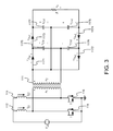
FIG. 3 is a circuit diagram of an isolation voltage-quadrupling DC converter used in the soft-switching inverter shown in FIG. 2;
FIG. 4 is a chart of operative ranges of the isolation voltage-quadrupling DC converter shown in FIG. 3;
FIG. 5 is a circuit diagram of the isolation voltage-quadrupling DC converter shown in FIG. 3 in modes 1 and 4;
FIG. 6 is a circuit diagram of the isolation voltage-quadrupling DC converter shown in FIG. 3 in mode 2;
FIG. 7 is a circuit diagram of the isolation voltage-quadrupling DC converter shown in FIG. 3 in mode 3;
FIG. 8 is a circuit diagram of the isolation voltage-quadrupling DC converter shown in FIG. 3 in mode 5;
FIG. 9 is a circuit diagram of the isolation voltage-quadrupling DC converter shown in FIG. 3 in mode 6;
FIG. 10 shows driving signals from main switches and clamping switches of the soft-switching inverter shown in FIG. 2 at a maximum value;
FIG. 11 shows driving signals from a line-frequency select switch on an AC side of the isolation voltage-quadrupling DC converter shown in FIG. 3;
FIG. 12 shows waveforms on a high-voltage side of the isolation voltage-quadrupling DC converter shown in FIG. 3;
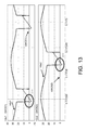
FIG. 13 shows soft-switching waveforms of the main switches on a low-voltage side of the isolation voltage-quadrupling DC converter shown in FIG. 3; and
FIG. 14 shows soft-switching waveforms of the clamping switches on the low-voltage side of the isolation voltage-quadrupling DC converter shown in FIG. 2.
DETAILED DESCRIPTION OF PREFERRED EMBODIMENT
Referring to FIG. 1, there is shown a photovoltaic system including a soft-switching high-efficiency inverter 10 according to the preferred embodiment of the present invention. The photovoltaic system includes the inverter 10, a solar cell module 20 and a controlling stage for obtaining a maximum power of the solar cell module 20. The controlling stage includes a zero-crossing detect circuit 40, a line-frequency select switch 50, a maximum power point tracking controller 60, a sensing circuit 70 and a driving circuit 80.
At a rear end, the inverter 10 is connected to the grid 30 or the load. The solar cell module 20 provides a DC power supply to provide a DC output voltage Vpv and a DC output current Ipv. The DC power supply is converted to an AC power supply that is provided to the grid 30. However, the inverter 10 is not limited to use in a photovoltaic system. The inverter 10 can be used to boost and convert any DC power supply to an AC power supply.
Referring to FIGS. 1 and 2, the soft-switching high-efficiency inverter 10 includes an isolation voltage-quadrupling DC converter 11 and an AC selecting switch unit 12. The isolation voltage-quadrupling DC converter 11 includes an isolation transformer 111.
On a low-voltage side, the isolation transformer 111 includes a first inductor (L1) 112, a second inductor (L2) 113, a first main switch (S1) 114, a second main switch (S2) 115 and an active clamping circuit 116. The active clamping circuit 116 includes a first clamping switch (Sc1) 1161, a second clamping switch (Sc2) 1162 and a clamping capacitor (Cc) 1163.
On a high-voltage side, the isolation transformer 111 includes a booster 117. The booster 117 includes a first diode (Db1) 1171, a second diode (Db2) 1172, a third diode (Do1) 1173, a fourth diode (Do2) 1174, a first capacitor (Cb1) 1175, a second capacitor (Cb2) 1176, a third capacitor (Co1) 1177 and a fourth capacitor (CO2) 1178.
Thus, the isolation voltage-quadrupling DC converter 11 receives DC from a DC power supply, converts the voltage of the DC, executes half-sine modulation on the DC, and causes the DC power supply to operate in a continuous conduction mode (“CCM”) to provide a continuous half-sine current.
The AC selecting switch unit 12 is electrically connected to the isolation voltage-quadrupling DC converter 11 and the grid 30. The AC selecting switch unit 12 includes a first power switch (QA) 121, a second power switch (QA′) 122, a third power switch (QB) 123 and a fourth power switch (QB′) 124. By synchronous switching between the AC selecting switch unit 12 and the grid 30, the half-sine current is converted to a sine current. A low-frequency switch portion is filtered from the sine current by a filtering inductor 13 and a filtering capacitor 14. Thus, there is provided an output sine current at the same voltage as the grid 30. Thus, electricity may be provided to a load or the grid 30.
Referring to FIG. 1, the solar cell module 20 is the input to the system. The power of the solar cell module 20 is influenced by irradiance and temperature. The line-frequency switch 50 is electrically connected to the inverter 10 via the zero-crossing detect circuit 40. The line-frequency switch 50 receives an output voltage and current from the inverter 10 to produce driving signals for driving the power switches 121 to 124 of the AC selecting switch unit 12.
The sensing circuit 70 is electrically connected to the solar cell module 20. On sensing the DC output voltage Vpv and the DC output current Ipv from the solar cell module 20, the sensing circuit 70 executes controlling stage calculation and provides a pulse width modulation (“PWM”) signal to modulate the operative voltage or current of the solar cell module 20 to track the maximum power point.
The maximum power point tracking controller 60 is electrically connected to the sensing circuit 70 to calculate a maximum power point tracking command.
The driving circuit 80 is electrically connected to the maximum power point tracking controller 60, the line-frequency switch 50 and the inverter 10. The driving circuit 80 receives a half-sine PWM signal from the maximum power point tracking controller 60. The driving circuit 80 receives the driving signals from the line-frequency switch 50 and accordingly drives the isolation voltage-quadrupling DC converter 11 and the AC selecting switch unit 12 of the inverter 10.
The inverter 10 is electrically connected to the solar cell module 20. Under control, the inverter 10 converts the DC power supply to a half-sine current in a continuous conduction mode. Then, the AC selecting switch and the grid are switched synchronously to convert the half-sine current to a sine current at the same voltage as the grid 30. Thus, a unit power factor is fed to the grid 30 to overcome the drawbacks of the prior art and increase the efficiency of the conversion of sun light to electricity.
Referring to FIG. 3, the isolation voltage-quadrupling DC converter 11 is the primary booster in the soft-switching inverter 10. The operation of the isolation voltage-quadrupling DC converter 11 will be described referring to FIGS. 4 through 9.
Referring to FIG. 4, the first main switch 114 and the second main switch 115 are switched alternately. The difference between their phases is 180 degrees. As shown, there are 6 operative regions.
Referring to FIG. 5, shown is an equivalent circuit of the isolation voltage-quadrupling DC converter 11 in operative mode 1. The first main switch 114 and the second main switch 115 are on. Their input ends recharge the first inductor 112 and second inductor 113. Two-phase inductance currents iL1 and iL2 increase linearly. The third capacitor 1177 and the fourth capacitor 1178 provide electricity to the load.
Referring to FIG. 6, shown is an equivalent circuit of the isolation voltage-quadrupling DC converter 11 in operative mode 2. The first main switch 114 is on. The second main switch 115 is off. The first inductor 112 continues to be recharged. The inductance current iL2 continues to go to the high-voltage side via the isolation transformer 111. The first capacitor 1175 recharges the third capacitor 1177 to reach a voltage balance, i.e., VCb1+VCb2=VCo1. The capacitor third capacitor 1177 and the fourth capacitor 1178 provide electricity to the load.
Referring to FIG. 7, shown is an equivalent circuit of the isolation voltage-quadrupling DC converter in mode 3. The first main switch 114 is on. The second main switch 115 is off. The first inductor 112 continues to be recharged. The inductance current iL2 continues to go to the high-voltage side to recharge the second capacitor 1176 and, together with the first capacitor 1175, recharge the third capacitor 1177. The first capacitor 1175 and the second capacitor 1176 provide electricity to the load.
In mode 4, the equivalent circuit of the isolation voltage-quadrupling DC converter 11 is like that is shown in FIG. 5.
Referring to FIG. 8, show is an equivalent circuit of the isolation voltage-quadrupling DC converter 11 in mode 5. The first main switch 114 is off. The second main switch 115 is on. The second inductor 113 continues to be recharged. The inductance current iL1 continues to go the high-voltage side via the isolation transformer and, together with the second capacitor 1176, recharge the fourth capacitor 1178 to reach a voltage balance, i.e., VCb1+VCb2=VCo2. The third capacitor 1177 and the fourth capacitor 1178 provide electricity to the load.
Referring to FIG. 9, shown is an equivalent circuit of the isolation voltage-quadrupling DC converter 11 in mode 6. The first main switch 114 is off. The second main switch 115 is on. The second inductor 113 continues to be recharged. The inductance current iL1 continues to go the high-voltage side to recharge the first capacitor 1175 and, together with the second capacitor 1176, recharge the fourth capacitor 1178. The third capacitor 1177 and the fourth capacitor 1178 provide electricity to the load. By inference with a mathematical model and simulation for verification, the step-up ratio is calculated as follows:
V o V IN = 4 n 1 - D
wherein n is the turn ratio of the isolation transformer 111. The isolation voltage-quadrupling DC converter 11 helps boost the output voltage of the solar cell module to the level of the grid to facilitate the provide of the electricity to the grid.
Referring to FIG. 10, there are shown switch signals on the primary side of the circuit, i.e., the driving signals when the main switches and the claiming switch are at the maximum voltage of the grid. As shown, the active clamping switch Sc2 and the main switch S2 are switched in a complementary manner, the active clamping switch Sc1 and the main switch S1 are switched in a complementary manner, and the difference between the phases of the main switch S1 and the main switch S2 is 180 degrees. When the main switch and the active clamping switch are switched, there is a dead time for soft switching.
Referring to FIG. 11, there are shown driving signals from a line-frequency select switch on an AC side of the isolation voltage-quadrupling DC converter 11. In addition, the switching signals of the AC selecting switch are shown. The frequency of the switching of the AC selecting switch is identical to that of the grid, and their phases are identical. In the AC selecting switch, there is only low-frequency switching synchronous with the grid. The AC selecting switch does not control the current. Therefore, there is a need for the inverter to produce a half-sine current that will later be converted to a sine current that is fed to the grid. To produce the half-sine current and boost the voltage for the grid, inductors L1 and L2 are connected to each other in parallel to achieve conversion. On the low-voltage side, four switches are switched to execute the half-sine modulation for a continuous on mode. After the isolation transformer connects the low-voltage current to the high-voltage side, the booster on the high-voltage side boosts the voltage of the solar cell module to the level of the grid so that the current can be fed to the grid.
Referring to FIGS. 12 through 14, the inverter produces a continuous half-sine current. The rear end of the inverter switches with the grid synchronously via the AC selecting switches QA, QA′, QB and QB′ to convert the half-sine current to the sine-current at the same voltage as the grid so that the unit power factor can be fed to the grid.
As discussed above, the soft-switching high-efficiency inverter 10 exhibits several advantages.
At first, the low-voltage side is isolated from the high-voltage side.
Secondly, the conversion efficiency is high. The switches on the low-voltage side are used together with the active clamping switches to achieve the zero-voltage soft switching. The low-frequency operation of the phase-changing switches on the AC side also helps increase the conversion efficiency.
Thirdly, the operative range is not limited because the active clamping switches are used. The step-up ratio is high to facilitate the step-up of the voltage of the solar cell module to the voltage of the grid so that the electricity can be fed to the grid. The inverter 10 is therefore suitable for use in a low-power photovoltaic system module with large voltage variation.
Fourthly, it is reliable. The life of an inverter is limited by the life of a capacitor used therein and the temperature. Referring to FIG. 2, the inverter 10 does not include any electrolysis capacitor. On both the high-voltage and low-voltage sides, small-capacity thin-film capacitors are used to screen high frequency of switching or transfer of energy to help boost the voltage, not store energy.
Fifthly, the leakage inductance and switch stress are low. The inverter 10 exhibits a high step-up ratio by nature without having to include a high turn ratio of the isolation transformer.
Sixthly, it is durable for including the switches for soft switching.
The present invention has been described via the detailed illustration of the preferred embodiment. Those skilled in the art can derive variations from the preferred embodiment without departing from the scope of the present invention. Therefore, the preferred embodiment shall not limit the scope of the present invention defined in the claims.

Claims (5)

The invention claimed is:
1. A soft-switching inverter including:
an isolation voltage-quadrupling DC converter including an isolation transformer, wherein the isolation transformer includes a first inductor, a second inductor, a first main switch, a second main switch and an active clamping circuit on a low-voltage side, wherein the active clamping circuit includes a first clamping switch, a second clamping switch and a clamping capacitor, wherein the isolation transformer includes a first diode, a second diode, a third diode, a fourth diode and a booster on a high-voltage side, wherein the booster includes a first capacitor, a second capacitor, a third capacitor and a fourth capacitor, wherein the isolation voltage-quadrupling DC converter receives a DC power supply, converts the voltage of the DC power supply, and executes half-sine modulation on the DC power supply for operation in a continuous conduction mode, thus a continuous half-sine current; and
an AC selecting switch unit electrically connected to the isolation voltage-quadrupling DC converter and the grid, wherein the AC selecting switch unit includes a first power switch, a second power switch, a third power switch and a fourth power switch, wherein the switches are switched in synchronization with the grid to convert the half-sine current to a sine current, wherein a low-frequency portion is filtered from the sine current with a filtering inductor and a filtering capacitor to render the output current a sine current at the same voltage as the grid so that electricity can be fed to the load or a unit power factor can be fed to the grid.
2. The soft-switching inverter according to claim 1, wherein the first main switch, the second clamping switch and the second main switch are switched in a complementary manner, wherein the second main switch, the first clamping switch and the first main switch are switched in a complementary manner.
3. The soft-switching inverter according to claim 1, wherein the difference between the phases of the first and second main switches is 180 degrees.
4. The soft-switching inverter according to claim 1, wherein the first clamping switch and the first main switch are switched, wherein the second clamping switch and the second main switch are switched to provide a dead time for soft switching.
5. The soft-switching inverter according to claim 1, wherein the step-up ratio is
V o V IN - 4 n 1 - D ,
wherein n stands for the turn ratio of the isolation transformer.
US13/483,102 2012-05-30 2012-05-30 Soft-switching inverter utilizing high step up ratio circuit with active clamping Expired - Fee Related US8699237B2 (en)

Priority Applications (1)

Application Number Priority Date Filing Date Title
US13/483,102 US8699237B2 (en) 2012-05-30 2012-05-30 Soft-switching inverter utilizing high step up ratio circuit with active clamping

Applications Claiming Priority (1)

Application Number Priority Date Filing Date Title
US13/483,102 US8699237B2 (en) 2012-05-30 2012-05-30 Soft-switching inverter utilizing high step up ratio circuit with active clamping

Publications (2)

Publication Number Publication Date
US20130322126A1 US20130322126A1 (en) 2013-12-05
US8699237B2 true US8699237B2 (en) 2014-04-15

Family

ID=49670062

Family Applications (1)

Application Number Title Priority Date Filing Date
US13/483,102 Expired - Fee Related US8699237B2 (en) 2012-05-30 2012-05-30 Soft-switching inverter utilizing high step up ratio circuit with active clamping

Country Status (1)

Country Link
US (1) US8699237B2 (en)

Cited By (5)

* Cited by examiner, † Cited by third party
Publication number Priority date Publication date Assignee Title
US9106150B2 (en) * 2011-12-02 2015-08-11 Darfon Electronics Corp. Battery free off-grid solar inverter system and control method thereof
US20160336873A1 (en) * 2014-01-10 2016-11-17 Sumitomo Electric Industries, Ltd. Power conversion device and three-phase alternating current power supply device
CN107017780A (en) * 2017-05-31 2017-08-04 青岛大学 The isolated form DC DC booster converters and its control method of a kind of band pull-up active clamp branch road
CN107017779A (en) * 2017-05-31 2017-08-04 青岛大学 A kind of band pulls down the isolated form DC DC booster converter control methods of active clamp branch road
US20230170812A1 (en) * 2021-11-30 2023-06-01 Texas Instruments Incorporated Power supply system with active clamping

Families Citing this family (10)

* Cited by examiner, † Cited by third party
Publication number Priority date Publication date Assignee Title
WO2014032156A1 (en) * 2012-08-27 2014-03-06 Bombardier Transportation Gmbh Adaptive soft switching control for power converter
US8619445B1 (en) 2013-03-15 2013-12-31 Arctic Sand Technologies, Inc. Protection of switched capacitor power converter
TWI495244B (en) * 2013-11-14 2015-08-01 Nat Univ Tsing Hua Bidirectional dc-dc converter system and circuit thereof
KR102317140B1 (en) * 2014-02-19 2021-10-22 엘지전자 주식회사 Power converting apparatus, and photovoltaic module
DE102014210502A1 (en) * 2014-06-03 2015-12-03 Fraunhofer-Gesellschaft zur Förderung der angewandten Forschung e.V. Power electronic circuit, power electronic power transformer and power electronic power transmission system
US11258371B2 (en) * 2016-02-16 2022-02-22 Psemi Corporation Switched capacitors for AC-DC applications
CN106300974B (en) * 2016-10-08 2019-03-22 山东大学 A kind of non-isolated high step-up ratio DC converter of modified and control method
CN108347167B (en) * 2017-01-25 2021-07-13 通用电气公司 System and method for soft switching DC-DC converter
KR102426371B1 (en) * 2017-09-22 2022-07-27 엘지전자 주식회사 Photovoltaic module
KR102565952B1 (en) * 2018-05-24 2023-08-09 엘지전자 주식회사 Power converting apparatus, and photovoltaic module including the same

Citations (6)

* Cited by examiner, † Cited by third party
Publication number Priority date Publication date Assignee Title
US5038267A (en) * 1990-05-03 1991-08-06 General Electric Company Soft-switching power converter for operation in discrete pulse modulation and pulse width modulation modes
US5198969A (en) * 1990-07-13 1993-03-30 Design Automation, Inc. Soft-switching full-bridge dc/dc converting
US5781419A (en) * 1996-04-12 1998-07-14 Soft Switching Technologies, Inc. Soft switching DC-to-DC converter with coupled inductors
US5946200A (en) * 1995-12-02 1999-08-31 Korea Electrotechnology Research Institute Circulating current free type high frequency soft switching pulsewidth modulated full bridge DC/DC converter
US6038142A (en) * 1998-06-10 2000-03-14 Lucent Technologies, Inc. Full-bridge isolated Current Fed converter with active clamp
US20030198064A1 (en) * 2002-01-16 2003-10-23 Ballard Power Systems Corporation Device and method of commutation control for an isolated boost converter

Patent Citations (7)

* Cited by examiner, † Cited by third party
Publication number Priority date Publication date Assignee Title
US5038267A (en) * 1990-05-03 1991-08-06 General Electric Company Soft-switching power converter for operation in discrete pulse modulation and pulse width modulation modes
US5198969A (en) * 1990-07-13 1993-03-30 Design Automation, Inc. Soft-switching full-bridge dc/dc converting
US5946200A (en) * 1995-12-02 1999-08-31 Korea Electrotechnology Research Institute Circulating current free type high frequency soft switching pulsewidth modulated full bridge DC/DC converter
US5781419A (en) * 1996-04-12 1998-07-14 Soft Switching Technologies, Inc. Soft switching DC-to-DC converter with coupled inductors
US6038142A (en) * 1998-06-10 2000-03-14 Lucent Technologies, Inc. Full-bridge isolated Current Fed converter with active clamp
US20030198064A1 (en) * 2002-01-16 2003-10-23 Ballard Power Systems Corporation Device and method of commutation control for an isolated boost converter
US6937483B2 (en) * 2002-01-16 2005-08-30 Ballard Power Systems Corporation Device and method of commutation control for an isolated boost converter

Cited By (8)

* Cited by examiner, † Cited by third party
Publication number Priority date Publication date Assignee Title
US9106150B2 (en) * 2011-12-02 2015-08-11 Darfon Electronics Corp. Battery free off-grid solar inverter system and control method thereof
US20160336873A1 (en) * 2014-01-10 2016-11-17 Sumitomo Electric Industries, Ltd. Power conversion device and three-phase alternating current power supply device
US9748865B2 (en) * 2014-01-10 2017-08-29 Sumitomo Electric Industries, Ltd. Power conversion device and three-phase alternating current power supply device
CN107017780A (en) * 2017-05-31 2017-08-04 青岛大学 The isolated form DC DC booster converters and its control method of a kind of band pull-up active clamp branch road
CN107017779A (en) * 2017-05-31 2017-08-04 青岛大学 A kind of band pulls down the isolated form DC DC booster converter control methods of active clamp branch road
CN107017780B (en) * 2017-05-31 2019-05-10 青岛大学 A kind of the isolated form DC-DC boost converter and its control method of band pull-up active clamp branch
US20230170812A1 (en) * 2021-11-30 2023-06-01 Texas Instruments Incorporated Power supply system with active clamping
US11863077B2 (en) * 2021-11-30 2024-01-02 Texas Instruments Incorporated Power supply system with active clamping

Also Published As

Publication number Publication date
US20130322126A1 (en) 2013-12-05

Similar Documents

Publication Publication Date Title
US8699237B2 (en) Soft-switching inverter utilizing high step up ratio circuit with active clamping
KR101132102B1 (en) Power conversion apparatus, power conditioner and power generation system
US20090086520A1 (en) Grid-Connected Power Conditioner and Grid-Connected Power Supply System
AU2020227736B2 (en) Power converters and methods of controlling same
Eydi et al. A new high gain DC-DC boost converter with continuous input and output currents
Li et al. A method of power decoupling for long life micro-inverter
Patil et al. Design and development of MPPT algorithm for high efficient DC-DC converter for solar energy system connected to grid
Ramasamy et al. Photovoltaic based dynamic voltage restorer with outage handling capability using PI controller
Lakpathi et al. An effective high step-up interleaved DC-DC converter photovoltaic grid connection System
Zeng et al. A soft-switched four-port DC-DC converter for renewable energy integration
Shafeeque et al. A novel single-phase single-stage inverter for solar applications
Thulasiyammal et al. An efficient method of MPPT tracking system of a solar powered Uninterruptible Power Supply application
Ronilaya et al. A double stage micro-inverter for optimal power flow control in grid connected PV system
Babu et al. Performance analysis of novel three phase High step-up dc-dc interleaved boost converter using coupled inductor
Prakash et al. Solar Photovoltaic Array fed Push-Pull Buck DC-DC Converter for Telecom Load
Paul et al. Modeling and analysis of PV micro-inverter
Tayebi et al. Advanced phase-skipping control with improved efficiency of three-phase micro-inverters
Ravichandrudu et al. Design and performance of a bidirectional isolated Dc-Dc converter for renewable power system
Das et al. Novel pv fed three phase single power stage system for stand-alone applications
Hu et al. Modeling of a new multiple input converter configuration for PV/battery system with MPPT
KR20150102765A (en) Photovoltaics System comprising energy storage means and Control method thereof
TW201347391A (en) Inverter with soft-switching
Meneses et al. Single-stage grid-connected forward microinverter with boundary mode control
Manohar et al. Performance Evaluation of a New Closed loop high setup DC-DC converter for photo voltaic application
Gandomkar et al. Inductive-boost switched-capacitor DC/DC converter for maximum power point tracking photovoltaic systems

Legal Events

Date Code Title Description
AS Assignment

Owner name: NATIONAL TSING HUA UNIVERSITY, TAIWAN

Free format text: ASSIGNMENT OF ASSIGNORS INTEREST;ASSIGNORS:PAN, CHING-TSAI;CHENG, MING-CHIEH;CHEN, EN-LIN;AND OTHERS;REEL/FRAME:028293/0713

Effective date: 20120501

STCF Information on status: patent grant

Free format text: PATENTED CASE

FPAY Fee payment

Year of fee payment: 4

FEPP Fee payment procedure

Free format text: MAINTENANCE FEE REMINDER MAILED (ORIGINAL EVENT CODE: REM.); ENTITY STATUS OF PATENT OWNER: SMALL ENTITY

LAPS Lapse for failure to pay maintenance fees

Free format text: PATENT EXPIRED FOR FAILURE TO PAY MAINTENANCE FEES (ORIGINAL EVENT CODE: EXP.); ENTITY STATUS OF PATENT OWNER: SMALL ENTITY

STCH Information on status: patent discontinuation

Free format text: PATENT EXPIRED DUE TO NONPAYMENT OF MAINTENANCE FEES UNDER 37 CFR 1.362

FP Lapsed due to failure to pay maintenance fee

Effective date: 20220415