US869901A - Tappet. - Google Patents
Tappet. Download PDFInfo
- Publication number
- US869901A US869901A US35269807A US1907352698A US869901A US 869901 A US869901 A US 869901A US 35269807 A US35269807 A US 35269807A US 1907352698 A US1907352698 A US 1907352698A US 869901 A US869901 A US 869901A
- Authority
- US
- United States
- Prior art keywords
- tappet
- rod
- pieces
- cavities
- slots
- Prior art date
- Legal status (The legal status is an assumption and is not a legal conclusion. Google has not performed a legal analysis and makes no representation as to the accuracy of the status listed.)
- Expired - Lifetime
Links
Images
Classifications
-
- A—HUMAN NECESSITIES
- A61—MEDICAL OR VETERINARY SCIENCE; HYGIENE
- A61F—FILTERS IMPLANTABLE INTO BLOOD VESSELS; PROSTHESES; DEVICES PROVIDING PATENCY TO, OR PREVENTING COLLAPSING OF, TUBULAR STRUCTURES OF THE BODY, e.g. STENTS; ORTHOPAEDIC, NURSING OR CONTRACEPTIVE DEVICES; FOMENTATION; TREATMENT OR PROTECTION OF EYES OR EARS; BANDAGES, DRESSINGS OR ABSORBENT PADS; FIRST-AID KITS
- A61F2/00—Filters implantable into blood vessels; Prostheses, i.e. artificial substitutes or replacements for parts of the body; Appliances for connecting them with the body; Devices providing patency to, or preventing collapsing of, tubular structures of the body, e.g. stents
- A61F2/02—Prostheses implantable into the body
- A61F2/30—Joints
- A61F2/30721—Accessories
- A61F2/30734—Modular inserts, sleeves or augments, e.g. placed on proximal part of stem for fixation purposes or wedges for bridging a bone defect
-
- E—FIXED CONSTRUCTIONS
- E04—BUILDING
- E04B—GENERAL BUILDING CONSTRUCTIONS; WALLS, e.g. PARTITIONS; ROOFS; FLOORS; CEILINGS; INSULATION OR OTHER PROTECTION OF BUILDINGS
- E04B5/00—Floors; Floor construction with regard to insulation; Connections specially adapted therefor
- E04B5/02—Load-carrying floor structures formed substantially of prefabricated units
- E04B5/10—Load-carrying floor structures formed substantially of prefabricated units with metal beams or girders, e.g. with steel lattice girders
-
- Y—GENERAL TAGGING OF NEW TECHNOLOGICAL DEVELOPMENTS; GENERAL TAGGING OF CROSS-SECTIONAL TECHNOLOGIES SPANNING OVER SEVERAL SECTIONS OF THE IPC; TECHNICAL SUBJECTS COVERED BY FORMER USPC CROSS-REFERENCE ART COLLECTIONS [XRACs] AND DIGESTS
- Y10—TECHNICAL SUBJECTS COVERED BY FORMER USPC
- Y10T—TECHNICAL SUBJECTS COVERED BY FORMER US CLASSIFICATION
- Y10T24/00—Buckles, buttons, clasps, etc.
- Y10T24/39—Cord and rope holders
- Y10T24/3958—Screw clamp
-
- Y—GENERAL TAGGING OF NEW TECHNOLOGICAL DEVELOPMENTS; GENERAL TAGGING OF CROSS-SECTIONAL TECHNOLOGIES SPANNING OVER SEVERAL SECTIONS OF THE IPC; TECHNICAL SUBJECTS COVERED BY FORMER USPC CROSS-REFERENCE ART COLLECTIONS [XRACs] AND DIGESTS
- Y10—TECHNICAL SUBJECTS COVERED BY FORMER USPC
- Y10T—TECHNICAL SUBJECTS COVERED BY FORMER US CLASSIFICATION
- Y10T403/00—Joints and connections
- Y10T403/49—Member deformed in situ
- Y10T403/4941—Deformation occurs simultaneously with action of separate, diverse function, joint component
-
- Y—GENERAL TAGGING OF NEW TECHNOLOGICAL DEVELOPMENTS; GENERAL TAGGING OF CROSS-SECTIONAL TECHNOLOGIES SPANNING OVER SEVERAL SECTIONS OF THE IPC; TECHNICAL SUBJECTS COVERED BY FORMER USPC CROSS-REFERENCE ART COLLECTIONS [XRACs] AND DIGESTS
- Y10—TECHNICAL SUBJECTS COVERED BY FORMER USPC
- Y10T—TECHNICAL SUBJECTS COVERED BY FORMER US CLASSIFICATION
- Y10T403/00—Joints and connections
- Y10T403/49—Member deformed in situ
- Y10T403/4966—Deformation occurs simultaneously with assembly
Definitions
- This invention relates to improvements in tappets used for stamp mills, my object being to produce such a tappet as will be strong and ei'i'ective, which may easily be removed when desired; and one which can be easily manufactured and installed.
- These objects I accomplish by means of a two piece tappet provided with an interior biting surface adapted to engage with the rod, and a novel means for binding said two pieces securely together on the rod; also by such other and further construction as will appear by a perusal of the following specification and claims.
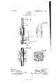
- Figure 1 is a side elevation showing my improved tappet installed in position.
- Fig. 2 is a view enlarged taken on a line X X of Fig. 1.
- Fig. 3 is cross section enlarged taken on a line y y of Fig. 1.
- Fig. 4 is a side elevation of two of the locking keys.
- lugs 5 Arranged at the top and bottom of each of said pieces 2 and 3 and on each side thereof are lugs 5. Said lugs are provided with orifices 6 extending in alinement through the pieces 2 and 3 and adapted to receive clamp bolts 7 carrying nuts 8. Extending through the said pieces 2 and 3 at points nearer the rod l l l l 1 than are orifices 6 are key slots 9, 21.112 nged in similar order as are the orifices 6 in the said pieces 2 and 3. are wedge keys adapted to fit from opposite sides into the slots 9 for the purpose as will appear.
- a body comprising two members having flat contiguous faces and with oppo sitely disposed semi-circular cavities in said faces, the flat contiguous faces extending radially of the cavities and in alinement transversely of the cavities, said cavities having internal spaced serrations adapted to engage a rod and said members having transverse slots at opposite sides of the cavities, reversely-arranged wedges received in said slots from opposite sides of the body portions, and clamp bolts uniting the body members.
Landscapes
- Health & Medical Sciences (AREA)
- Engineering & Computer Science (AREA)
- Architecture (AREA)
- General Health & Medical Sciences (AREA)
- Public Health (AREA)
- Cardiology (AREA)
- Biomedical Technology (AREA)
- Heart & Thoracic Surgery (AREA)
- Vascular Medicine (AREA)
- Life Sciences & Earth Sciences (AREA)
- Animal Behavior & Ethology (AREA)
- Transplantation (AREA)
- Veterinary Medicine (AREA)
- Oral & Maxillofacial Surgery (AREA)
- Physics & Mathematics (AREA)
- Orthopedic Medicine & Surgery (AREA)
- Electromagnetism (AREA)
- Civil Engineering (AREA)
- Structural Engineering (AREA)
- Braking Arrangements (AREA)
Description
No. 869,901. PATENTE-D NOV. 5, 1907.
H. HAHN.
TAPPET.
APPLIOATION FILED JAN.17. 190?.
1a n 5 lllllli-llll ll ll amw'wboz 1720121 huh HENRY HAHN, OF STOCKTON, CALIFORNIA.
TAPPET.
Specification of Letters Patent.
Patented Nov. 5, 1907.
Application filed January 17.190'7- Serial No. 352,698.
To all whom it may concern:
Be it known that I, IIENRX United States, residing at Stockton,
IIAIIN, a citizen of the in the county of a San Joaquin, State of California, have invented cerbe a full, clear, and exact same, such as will enable others 1 ing the two pieces 2 and 3 tightly drawings, and the characters of reference marked therei on, which form a part of this application.
This invention relates to improvements in tappets used for stamp mills, my object being to produce such a tappet as will be strong and ei'i'ective, which may easily be removed when desired; and one which can be easily manufactured and installed. These objects I accomplish by means of a two piece tappet provided with an interior biting surface adapted to engage with the rod, and a novel means for binding said two pieces securely together on the rod; also by such other and further construction as will appear by a perusal of the following specification and claims.
In the accompanying drawings similar characters of reference indicate corresponding parts in the several views.
Figure 1 is a side elevation showing my improved tappet installed in position. Fig. 2 is a view enlarged taken on a line X X of Fig. 1. Fig. 3 is cross section enlarged taken on a line y y of Fig. 1. Fig. 4 is a side elevation of two of the locking keys.
1 designates the rod to which the tappet is secured. On said rod is secured a tappet composed of two pieces 2 and 3, the interior surfaces of said pieces 2 and 3 being provided with biting threads 4 or any other suitable biting surface. Arranged at the top and bottom of each of said pieces 2 and 3 and on each side thereof are lugs 5. Said lugs are provided with orifices 6 extending in alinement through the pieces 2 and 3 and adapted to receive clamp bolts 7 carrying nuts 8. Extending through the said pieces 2 and 3 at points nearer the rod l l l l l 1 than are orifices 6 are key slots 9, 21.112 nged in similar order as are the orifices 6 in the said pieces 2 and 3. are wedge keys adapted to fit from opposite sides into the slots 9 for the purpose as will appear.
In practice the pieces 2 and 3 are placed over the rod 1 as shown in Fig. 1. The wedge keys 10 are then inserted in the slots 9 and driven up tight thus bindtogether on the said rod 1. The bolts 7 are then inserted into the orifices 6, and the nuts 8 mounted thereon and tightened as much as is possible thus holding the parts 2 and 3 in their tightened position on the rod 1, and thus aiding and increasing the security of the tightening caused by the keys 10. The rough biting surfaces 4 grip the rod I thus also aiding to hold the tappet in a fixed position. Thus it will be seen that I have produced a simple form of tappet which substantially fulfils the objects of the invention as set forth in the preamble of this specification.
This specification sets forth in detail the present and preferred embodiment of my invention. In practice however deviations from such detail may be resorted to within the scope of the claims without departing from the spirit of my invention. I
Having thus described my invention what I claim as new and desire to secure by Letters Patent is:
In a device of the class described, a body comprising two members having flat contiguous faces and with oppo sitely disposed semi-circular cavities in said faces, the flat contiguous faces extending radially of the cavities and in alinement transversely of the cavities, said cavities having internal spaced serrations adapted to engage a rod and said members having transverse slots at opposite sides of the cavities, reversely-arranged wedges received in said slots from opposite sides of the body portions, and clamp bolts uniting the body members.
In testimony whereof I affix my signature in presence of two witnesses.
HENRY HAHN.
Witnesses Inncy S. WnBsTmz,
Josnnn B. WEBSTER.
Priority Applications (1)
| Application Number | Priority Date | Filing Date | Title |
|---|---|---|---|
| US35269807A US869901A (en) | 1907-01-17 | 1907-01-17 | Tappet. |
Applications Claiming Priority (1)
| Application Number | Priority Date | Filing Date | Title |
|---|---|---|---|
| US35269807A US869901A (en) | 1907-01-17 | 1907-01-17 | Tappet. |
Publications (1)
| Publication Number | Publication Date |
|---|---|
| US869901A true US869901A (en) | 1907-11-05 |
Family
ID=2938348
Family Applications (1)
| Application Number | Title | Priority Date | Filing Date |
|---|---|---|---|
| US35269807A Expired - Lifetime US869901A (en) | 1907-01-17 | 1907-01-17 | Tappet. |
Country Status (1)
| Country | Link |
|---|---|
| US (1) | US869901A (en) |
Cited By (2)
| Publication number | Priority date | Publication date | Assignee | Title |
|---|---|---|---|---|
| US2887902A (en) * | 1958-01-10 | 1959-05-26 | Bear Mfg Co | Bob weight for balance testing of counterbalanced crankshaft |
| US5492458A (en) * | 1994-01-04 | 1996-02-20 | Horng; Alex | Stator of electric fan |
-
1907
- 1907-01-17 US US35269807A patent/US869901A/en not_active Expired - Lifetime
Cited By (2)
| Publication number | Priority date | Publication date | Assignee | Title |
|---|---|---|---|---|
| US2887902A (en) * | 1958-01-10 | 1959-05-26 | Bear Mfg Co | Bob weight for balance testing of counterbalanced crankshaft |
| US5492458A (en) * | 1994-01-04 | 1996-02-20 | Horng; Alex | Stator of electric fan |
Similar Documents
| Publication | Publication Date | Title |
|---|---|---|
| US869901A (en) | Tappet. | |
| US569527A (en) | Cotter-pin press | |
| US1256824A (en) | Cable-clamp. | |
| US853237A (en) | Nut-lock. | |
| US1523146A (en) | Nut lock | |
| US1181871A (en) | Scissors. | |
| US969325A (en) | Threadless nut-lock. | |
| US808648A (en) | Anticreeping device for rails. | |
| US1801505A (en) | Nut lock | |
| US703680A (en) | Tappet for stamp-mills. | |
| US735794A (en) | Fastening. | |
| US1429706A (en) | Wheel-spoke tightener | |
| US383268A (en) | Itjvesses | |
| US763582A (en) | Vehicle-shaft and clip. | |
| US477222A (en) | Nut-lock | |
| US538361A (en) | Tire and felly clamp | |
| US542683A (en) | John nase | |
| US555994A (en) | Tire-tightener | |
| US242504A (en) | Tire-tightener | |
| US641355A (en) | Tire-tightener. | |
| US206125A (en) | Improvement in felly joint and tightener | |
| US1031938A (en) | Rail-seat on tie. | |
| US565169A (en) | Eccentric | |
| US522086A (en) | Harrow | |
| US741803A (en) | Cross-timber clamp. |