US8695348B2 - Combustor and gas turbine - Google Patents
Combustor and gas turbine Download PDFInfo
- Publication number
- US8695348B2 US8695348B2 US12/913,114 US91311410A US8695348B2 US 8695348 B2 US8695348 B2 US 8695348B2 US 91311410 A US91311410 A US 91311410A US 8695348 B2 US8695348 B2 US 8695348B2
- Authority
- US
- United States
- Prior art keywords
- oil
- combustor
- inflow portion
- guide portion
- oil chamber
- Prior art date
- Legal status (The legal status is an assumption and is not a legal conclusion. Google has not performed a legal analysis and makes no representation as to the accuracy of the status listed.)
- Active, expires
Links
Images


Classifications
-
- F—MECHANICAL ENGINEERING; LIGHTING; HEATING; WEAPONS; BLASTING
- F02—COMBUSTION ENGINES; HOT-GAS OR COMBUSTION-PRODUCT ENGINE PLANTS
- F02C—GAS-TURBINE PLANTS; AIR INTAKES FOR JET-PROPULSION PLANTS; CONTROLLING FUEL SUPPLY IN AIR-BREATHING JET-PROPULSION PLANTS
- F02C7/00—Features, components parts, details or accessories, not provided for in, or of interest apart form groups F02C1/00 - F02C6/00; Air intakes for jet-propulsion plants
- F02C7/22—Fuel supply systems
- F02C7/232—Fuel valves; Draining valves or systems
-
- F—MECHANICAL ENGINEERING; LIGHTING; HEATING; WEAPONS; BLASTING
- F02—COMBUSTION ENGINES; HOT-GAS OR COMBUSTION-PRODUCT ENGINE PLANTS
- F02C—GAS-TURBINE PLANTS; AIR INTAKES FOR JET-PROPULSION PLANTS; CONTROLLING FUEL SUPPLY IN AIR-BREATHING JET-PROPULSION PLANTS
- F02C7/00—Features, components parts, details or accessories, not provided for in, or of interest apart form groups F02C1/00 - F02C6/00; Air intakes for jet-propulsion plants
- F02C7/22—Fuel supply systems
- F02C7/222—Fuel flow conduits, e.g. manifolds
-
- F—MECHANICAL ENGINEERING; LIGHTING; HEATING; WEAPONS; BLASTING
- F02—COMBUSTION ENGINES; HOT-GAS OR COMBUSTION-PRODUCT ENGINE PLANTS
- F02C—GAS-TURBINE PLANTS; AIR INTAKES FOR JET-PROPULSION PLANTS; CONTROLLING FUEL SUPPLY IN AIR-BREATHING JET-PROPULSION PLANTS
- F02C9/00—Controlling gas-turbine plants; Controlling fuel supply in air- breathing jet-propulsion plants
- F02C9/26—Control of fuel supply
- F02C9/40—Control of fuel supply specially adapted to the use of a special fuel or a plurality of fuels
-
- F—MECHANICAL ENGINEERING; LIGHTING; HEATING; WEAPONS; BLASTING
- F23—COMBUSTION APPARATUS; COMBUSTION PROCESSES
- F23K—FEEDING FUEL TO COMBUSTION APPARATUS
- F23K5/00—Feeding or distributing other fuel to combustion apparatus
- F23K5/02—Liquid fuel
- F23K5/06—Liquid fuel from a central source to a plurality of burners
-
- F—MECHANICAL ENGINEERING; LIGHTING; HEATING; WEAPONS; BLASTING
- F23—COMBUSTION APPARATUS; COMBUSTION PROCESSES
- F23R—GENERATING COMBUSTION PRODUCTS OF HIGH PRESSURE OR HIGH VELOCITY, e.g. GAS-TURBINE COMBUSTION CHAMBERS
- F23R3/00—Continuous combustion chambers using liquid or gaseous fuel
- F23R3/28—Continuous combustion chambers using liquid or gaseous fuel characterised by the fuel supply
Definitions
- the present invention relates to a combustor and a gas turbine.
- Combustors used in gas turbines are classified into a gas combustion type, an oil combustion type, and a dual type, which is a combination of the gas combustion and oil combustion types.
- the oil combustion type or dual type combustor is equipped with a fuel oil supply system in order to supply fuel oil to a plurality of nozzles arranged around the central axis of the combustor.
- the fuel oil supply system includes a plurality of oil supply tubes and an oil chamber. Each of the oil supply tubes connects the base end of each nozzle to the oil chamber.
- the oil chamber is formed inside a nozzle tube base supporting the base end of each nozzle, and communicates with each nozzle via each supply tube.
- the fuel oil from the oil chamber of the combustor needs to be sufficiently removed. This is because the fuel oil inside the oil chamber is carbonized (caulked) due to heat transferred from a casing and there is a possible that the carbonized fuel oil blocks the oil supply tube or the fuel oil ejection portion at the front end of the nozzle when the fuel oil remains in the oil chamber.
- the gas turbine needs to be cleaned during stopping the operation thereof. For this reason, the operating efficiency of the gas turbine degrades.
- the oil chamber is formed to have a cross-star-shaped cross-section when viewed in the axial direction, fuel is transferred on a curved surface forming the inner wall of the oil chamber to be guided toward the supply path, and the fuel is blown away by compressed air to be discharged to the outside, thereby reducing the amount of the fuel remaining inside the oil chamber.
- the present invention is contrived in consideration of such circumstances, and an object of the present invention is to sufficiently remove the fuel oil in the oil chamber when discharging the fuel oil from the oil chamber.
- the present invention adopts the following means.
- a combustor of the present invention includes: a plurality of nozzles which is arranged around the central axis of a combustor and of which each base end is connected to an oil supply tube; a nozzle tube base which supports the plurality of nozzles and includes an oil chamber supplying fuel to the nozzles via an oil inflow portion provided in each oil supply tube; a first guide portion which faces the center of the combustor inside the oil chamber and guides the oil remaining inside the oil chamber to the oil inflow portion; and a second guide portion which faces the base end of the combustor inside the oil chamber and guides the oil remaining inside the oil chamber to the oil inflow portion, wherein the first guide portion includes a first inclination surface that is located between the adjacent oil inflow portions and is inclined in a direction away from the center of the combustor as it becomes closer to one oil inflow portion and a second inclination surface that is inclined in a direction away from the center of the combustor as it becomes closer to the other oil inflow portion,
- the oil chamber includes the first guide portion
- the first inclination surface of the first guide portion guides the fuel oil to one oil inflow portion
- the second inclination surface guides the fuel oil to the other oil inflow portion when discharging the fuel oil from the oil chamber.
- the oil chamber includes the second guide portion
- the third inclination surface of the second guide portion guides the fuel oil on the second guide portion toward the oil inflow portion.
- the fuel oil between two adjacent oil inflow portions is guided toward at least one of the two oil inflow portions, and the fuel oil reaching the second guide portion is guided toward the oil inflow portion. Accordingly, since the fuel oil is collected and discharged from the oil inflow portion, it is possible to sufficiently remove the fuel oil.
- the angle formed between the third inclination surface and the central axis of the combustor may be larger than the angle formed between the central axis of the combustor and the horizontal line.
- the oil inflow portion may come into contact with an area which is a part of the inner surface of the oil chamber and is the farthest from the center of the combustor.
- the oil inflow portion may include a base end opening which is formed in the oil supply tube and is opened toward the base end of the combustor.
- the oil inflow portion includes the base end opening which is opened toward the base end of the combustor, it is possible to allow the fuel oil to flow into the oil supply tube in a simple configuration.
- the oil inflow portion may include a perforation hole which is formed in a tube wall of the oil supply tube.
- the oil inflow portion includes the perforation hole formed in the tube wall, it is possible to allow the fuel oil to flow into the oil supply tube from the perforation hole.
- the oil chamber may include a third guide portion which faces the outer periphery of the combustor inside the oil chamber, is formed to be convex outward in the radial direction of the combustor, and guides the oil remaining inside the oil chamber to the oil inflow portion.
- the third guide portion faces the outer periphery of the combustor inside the oil chamber, is formed to be convex outward in the radial direction of the combustor, and guides the oil remaining in the oil chamber to the oil inflow portion, the fuel oil from the oil chamber is guided downward along the third guide portion. Accordingly, since the fuel oil is consequently collected and discharged from the oil inflow portion, it is possible to sufficiently remove the fuel oil.
- the nozzle tube base may include a plurality of the oil chambers.
- the nozzle tube base includes the plurality of oil chambers, when the fuel oil is supplied to one oil chamber, and the supply of the fuel oil to the other thereof is stopped, it is possible to easily perform the partial load operation by ejecting the fuel oil only from the nozzle corresponding to the oil chamber to which the fuel oil is supplied. Further, since the fuel oil is suppressed from remaining by providing the plurality of oil chambers, it is possible to perform the partial load operation and the rated load operation, and to promptly switch the partial load operation to the operation stop or vice versa.
- the nozzle tube base may be formed by a combination of a first member including the first guide portion and a second member including the second guide portion, and the second member may be disposed in the central axial direction of the combustor to overlap with the first member.
- the nozzle tube base includes the first member having the first guide portion and the second member having the second guide portion, the structure thereof is simple, and hence the assembling efficiency and the processing efficiency are excellent.
- the base end opening of the oil inflow portion may face the first member, and the oil supply tube may penetrate the second member.
- the first member faces the oil inflow portion and the oil supply tube is inserted through the second member, the structure thereof is simple, and hence the assembling efficiency and the processing efficiency are excellent.
- a gas turbine of the present invention includes: a compressor which compresses a hydraulic fluid; the above-described combustor which burns the hydraulic fluid compressed by the compressor; a turbine which is driven by the hydraulic fluid burned by the combustor.
- the gas turbine of the present invention since the gas turbine includes the above-described combustor, when the oil combustion is stopped or the oil combustion is switched to the gas combustion in the dual type, it is possible to sufficiently remove the fuel oil from the oil chamber of the combustor. Accordingly, it is possible to prevent the fuel oil supply system from being blocked by the carbonized fuel oil. Further, when the combustor is activated or the gas fuel is not stably supplied in the dual type, it is possible to promptly and stably perform the oil combustion even in a backup operation or the like, and to improve the operational reliability of the gas turbine.
- the combustor of the present invention it is possible to sufficiently remove the fuel oil from the oil chamber when discharging the fuel oil from the oil chamber.
- the gas turbine of the present invention it is possible to improve the operational reliability by sufficiently removing the fuel oil from the oil chamber.
- FIG. 1 is a schematic cross-sectional view illustrating an overall configuration of a gas turbine 1 according to a first embodiment of the present invention.
- FIG. 2 is an enlarged cross-sectional view illustrating a combustor 10 according to the first embodiment of the present invention.
- FIG. 3 is an exploded perspective view illustrating a nozzle tube base 20 according to the first embodiment of the present invention.
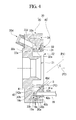
- FIG. 4 is a longitudinal sectional view illustrating the nozzle tube base 20 according to the first embodiment of the present invention.
- FIG. 5 is a schematic diagram illustrating a tube base body 30 according to the first embodiment of the present invention, and is a diagram when viewed in the direction I of FIG. 3 .
- FIG. 6 is a schematic diagram illustrating a cover body 40 according to the first embodiment of the present invention, and is a diagram when viewed in the direction II of FIG. 3 .
- FIG. 7 is a first operation explaining diagram according to the first embodiment of the present invention, and illustrates the combustor 10 taking an orientation where a direction of a line drawn from the central axis P 2 of an oil chamber 21 to the highest point of a first guide portion 33 c coincide with the gravity direction.
- FIG. 8 is a second operation explaining diagram according to the first embodiment of the present invention, and illustrates the combustor 10 taking an orientation where the direction of the line drawn from the central axis P 2 of the oil chamber 21 to the highest point of the first guide portion 33 c coincide with the gravity direction.
- FIG. 9 is a third operation explaining diagram according to the first embodiment of the present invention, and is a cross-sectional view taken along the line VI-VI of FIG. 7 .
- FIG. 10 is a fourth operation explaining diagram according to the first embodiment of the present invention, and illustrates the first combustor 10 taking an orientation where the direction of the line drawn from the central axis P 2 of the oil chamber 21 to the highest point of the first guide portion 33 c does not coincide with the gravity direction.
- FIG. 11 is a fifth operation explaining diagram according to the first embodiment of the invention, and illustrates the second combustor 10 taking an orientation where the direction of the line drawn from the central axis P 2 of the oil chamber 21 to the highest point of the first guide portion 33 c does not coincide with the gravity direction.
- FIG. 12 is a schematic configuration diagram illustrating a nozzle tube base 50 according to the second embodiment of the invention.
- FIG. 13 is a schematic configuration diagram illustrating a nozzle tube base 50 A which is a modified example of the nozzle tube base 50 according to the second embodiment of the invention.
- FIG. 1 is a schematic cross-sectional view illustrating an overall configuration of a gas turbine 1 according to a first embodiment of the invention.
- a rotational axis P 1 of a rotor 1 a is aligned with the horizontal direction
- the gas turbine 1 schematically includes a compressor 2 , a plurality of combustors 10 , and a turbine 3 .
- the compressor 2 generates compressed air A by receiving air as a hydraulic fluid.
- the plurality of combustors 10 communicates with the outlet of the compressor 2 .
- the plurality of combustors 10 generates a high temperature/pressure combustion gas B by mixing the compressed air A supplied from the compressor 2 with fuel and burning the mixture.
- the turbine 3 converts thermal energy of the combustion gas B fed from the combustor 10 into rotational energy of the rotor 1 a . Then, the rotational energy is transferred to a generator (not shown) connected to the rotor 1 a.
- the combustors 2 are arranged in a radial shape in which the central axis P 2 of each combustor is inclined with respect to the rotational axis P 1 of the rotor 1 a of the gas turbine 1 so that the inlet of the combustor 10 is more away from the rotational axis P 1 in the radial direction than the outlet thereof Further, in FIG. 2 , the angle formed between the central axis P 2 of the combustor and the rotational axis P 1 (the horizontal direction) is denoted by C.
- FIG. 2 is an enlarged cross-sectional view illustrating the combustor 10 .
- Each combustor 10 is of a dual type capable of performing both gas combustion and oil combustion. As shown in FIG. 2 , each combustor 10 includes an outer cylinder 11 , an inner cylinder 12 , a pilot nozzle 13 , a main nozzle 14 , and a tail cylinder 15 . Further, in the first embodiment, the dual type combustor 10 having the pilot nozzle 13 and the main nozzle 14 is described as an example, but the type is not particularly limited as long as the fuel nozzle is capable of performing oil combustion.
- the central axial direction (the direction of the central axis P 2 of the combustor) of the combustor 10 is simply referred to as the “axial direction”
- the direction around the central axis P 2 of the combustor is simply referred to as the “circumferential direction”
- the radial direction of the combustor 10 is simply referred to as the “radial direction.”
- the central axis of the outer cylinder 11 is aligned with the central axis P 2 of the combustor, and a flange 11 f extending outward in the radial direction from the outer periphery of one axial end is fixed to a casing 1 b .
- a base end portion 11 a of the other axial end of the outer cylinder 11 is provided with a fuel supply portion 10 a that supplies fuel gas and fuel oil to the main nozzle 14 , and a nozzle tube base 20 that supports the main nozzle 14 .
- the diameter of the inner cylinder 12 is formed to be smaller than that of the outer cylinder 11 , and the central axis is aligned with the central axis P 2 of the combustor.
- the inner cylinder 12 is fixed to the outer cylinder 11 via a support portion 12 f and the like extending in a radial shape from the vicinity of a base end opening 12 b.
- the gap between the outer cylinder 11 and the inner cylinder 12 serves as the channel of the compressed air A, and the compressed air A is introduced from the base end opening 12 b in the vicinity of the base end portion 11 a of the outer cylinder 11 to the inside of the combustor.
- the pilot nozzle 13 is formed in an elongated shape, and is disposed on the central axis P 2 of the combustor.
- the base end 13 b is supported by the nozzle tube base 20 and the like, and the vicinity of the front end 13 a is surrounded by the inner cylinder 12 .
- the pilot nozzle 13 forms a pilot flame from the front end 13 a by using fuel gas or fuel oil supplied from the fuel supply portion 10 a to the base end 13 b.
- the main nozzle 14 is formed in an elongated shape, and a plurality of (for example, eight) main nozzles are arranged at intervals in the circumferential direction.
- the plurality of main nozzles 14 extends in the axial direction with a gap in the radial direction from the central axis P 2 of the combustor, where each base end 14 b is supported by the nozzle tube base 20 .
- each main nozzle 14 fuel is supplied from the base end 14 b , and fuel is ejected from the front end 14 a , thereby forming a premixed gas obtained from the compressed air and fuel.
- a gas supply tube (not shown) and an oil supply tube 19 are connected to the main nozzle 14 , and the fuel gas and the fuel oil are supplied to the main nozzle 14 via the gas supply tube (not shown) and the oil supply tube 19 , whereby the fuel gas and the fuel oil flow from the base end 14 b to the front end 14 a.
- a base end opening 15 b is connected to a front end opening 12 a of the inner cylinder 12 , and a front end opening 15 a communicates with the turbine 3 .
- the tail cylinder 15 forms a flame (not shown) by burning the premixed gas formed by the main nozzle 14 .
- FIG. 3 is an exploded perspective view illustrating the nozzle tube base 20
- FIG. 4 is a longitudinal sectional view illustrating the nozzle tube base 20 .
- the nozzle tube base 20 includes a disk-shaped tube base body (a first member) 30 and a cover body (a second member) 40 .
- the nozzle tube base 20 is disposed in the outer cylinder 11 (refer to FIG. 2 ) while the central axis thereof is aligned with the central axis P 2 of the combustor, and includes an annular oil chamber 21 that is surrounded by the tube base body 30 and the cover body 40 .
- FIG. 5 is a diagram when viewed in the direction I of FIG. 3 . Further, in FIG. 5 , the portion corresponding to the cross-section of FIG. 4 is depicted by the line III-III.
- the tube base body 30 includes a central perforation hole 31 through which the pilot nozzle 13 is inserted; an inner peripheral groove 32 which surrounds the central perforation hole 31 so as to be coaxial with the central perforation hole 31 ; an oil groove 33 ; and an outer peripheral groove 34 .
- the oil groove 33 is formed in a gear shape when viewed from the top thereof. Specifically, an inner end surface 33 d of the oil groove 33 in the radial direction of the tube base body 30 is formed in an annular shape, and an outer end surface 33 a of the oil groove 33 is formed in an uneven shape.
- the outer end surface 33 a has a shape in which a tube disposing portion 33 b formed to be concave outward in the radial direction of the tube base body 30 and a first guide portion 33 c formed to be convex inward in the radial direction of the tube base body 30 are continuous in the circumferential direction of the tube base body 30 .
- the first guide portion 33 c is located between the adjacent tube disposing portions 33 b , and includes a first inclination surface 33 f which is inclined in a direction away from the center of the combustor as it becomes closer to one tube disposing portion 33 b , and a second inclination surface 33 g which is inclined in a direction away from the center of the combustor as it becomes closer to the other tube disposing portion 33 b.
- the tube disposing portion 33 b is recessed in a circular-arc shape outward in the radial direction of the tube base body 30 when viewed from the top thereof, and its curvature radius is set to be substantially the same as the outer radius of the oil supply tube 19 .
- Eight tube disposing portions 33 b are formed in the circumferential direction of the tube base body 30 at the same pitch.
- the first guide portion 33 c protrudes in a circular-arc shape inward in the radial direction when viewed from the top thereof.
- the curvature radius of the first guide portion 33 c is set to be larger than that of the tube disposing portion 33 b .
- the first guide portion 33 c is smoothly continuous to two tube disposing portions 33 b adjacent to each other.
- a bottom surface 33 e of the oil groove 33 extends in the circumferential direction at a predetermined position in the axial direction.
- a defining wall 30 a formed between the oil groove 33 and the outer peripheral groove 34 is provided with a circular-arc-shaped receiving portion 30 b which is formed to be lower by one stage than the edge of the tube disposing portion 33 b and is capable of receiving a protrusion portion 42 of the cover body 40 to be described later.
- a surface 30 c opposite to a surface provided with the oil groove 33 of the tube base body 30 is provided with an oil feeding opening 30 d which communicates with the oil groove 33 and is connected to the fuel supply portion 10 a (refer to FIG. 2 ).
- FIG. 6 is a diagram when viewed in the direction II of FIG. 3
- FIG. 7 is a cross-sectional view taken along the line V-V of FIG. 6 . Further, in FIG. 6 , the portion corresponding to the cross-section of FIG. 4 is depicted by the line IV-IV.
- the cover body 40 when viewed from the top of the cover body, the cover body 40 includes a plate portion 41 which is formed to be similar to the oil groove 33 , and a protrusion portion 42 which is provided on the wall surface 41 a of the plate portion 41 and protrudes in the axial direction from the portion protruding outward in the radial direction of the cover body 40 .
- the overall circumferential length of the outer end surface 40 a located on the outside of the cover body 40 in the radial direction is formed to be larger than the overall circumferential length of the outer end surface 33 a of the oil groove 33
- the overall circumferential length of the inner end surface 40 d located on the inside in the radial direction is formed to be smaller than the overall circumferential length of the inner end surface 33 d of the oil groove 33 .
- the protrusion portion 42 is formed in a substantially fan shape when viewed from the top thereof
- the protrusion portion 42 includes a cylindrical portion 42 b which is formed on the outside of the cover body 40 in the radial direction to have the same thickness, and a second guide portion 42 a which is widened in a circular-arc shape inward in the radial direction of the cylindrical portion 42 b to have a thickness which becomes gradually thinner as it moves away from the cylindrical portion 42 b .
- FIG. 4 the protrusion portion 42 includes a cylindrical portion 42 b which is formed on the outside of the cover body 40 in the radial direction to have the same thickness, and a second guide portion 42 a which is widened in a circular-arc shape inward in the radial direction of the cylindrical portion 42 b to have a thickness which becomes gradually thinner as it moves away from the cylindrical portion 42 b .
- the angle D formed between the central axis P 2 of the combustor and a third inclination surface 42 e as an inclination surface of the second guide portion 42 a in the longitudinal section is set to be larger than the angle C formed between the rotational axis P 1 and the central axis P 2 of the combustor.
- the cover body 40 covers the oil groove 33 while the protrusion portion 42 faces the tube base body 30 , and is fixed to the tube base body 30 by welding.
- the second guide portion 42 a is fitted to two first guide portions 33 c (refer to FIG. 5 ) adjacent to each other in the circumferential direction (refer to FIG. 6 ), and an inclination end surface 42 d of the second guide portion 42 a comes into close contact with the first guide portion 33 c .
- the nozzle tube base 20 is obtained by a combination of the tube base body 30 (the first member) having the first guide portion 33 c and the cover body 40 (the second member) having the second guide portion 42 a , and the cover body 40 overlaps with the tube base body 30 while being aligned with the central axial direction of the combustor.
- the first guide portion 33 c is continuous to the second guide portion 42 a in the circumferential direction of the tube base body 30 . Further, as shown in FIG. 5 , a part of the peripheral edge of the perforation hole 42 c of the cylindrical portion 42 b of the protrusion portion 42 of the cover body 40 is located so as to overlap with the tube disposing portion 33 b of the tube base body 30 in the axial direction of the tube base body 30 .
- the tube base body 30 , the cover body 40 , and the oil chamber 21 are formed. That is, the oil chamber is surrounded by an outer radial end surface 33 a , an inner radial end surface 33 d , and both axial wall surfaces ( 33 e and 41 a ) inside the nozzle tube base 20 , and is used to collect the fuel oil supplied from the oil feeding opening.
- each of the oil supply tubes 19 of eight main nozzles 14 is liquid-tightly inserted into each of eight perforation holes 42 c of the nozzle tube base 20 with an O-ring or the like (not shown).
- the base end of each oil supply tube 19 reaching the oil chamber 33 is provided with an oil inflow portion 19 a.
- the oil inflow portion 19 a includes a base end opening 19 b which is opened in the axial direction and a plurality of perforation holes 19 c which is formed in the tube wall of the oil supply tube 19 in the outer surface of the oil supply tube 19 .
- the base end opening 19 b is inserted to a position adjacently facing the bottom surface 33 e of the tube base body 30 .
- the outer peripheral surface of the oil inflow portion 19 a comes into contact with the tube disposing portion 33 b by inserting the oil supply tube 19 into the perforation hole 42 c overlapping with the tube disposing portion 33 b when viewed in the axial direction.
- the downstream side of the oil inflow portion 19 a of the oil supply tube 19 is surrounded by the cylindrical portion 42 b . That is, the oil inflow portion 19 a comes into contact with the area which is a part of the inner surface of the oil chamber 21 and is the farthest from the center of the combustor.
- a third inclination surface 42 e is located to be closer to the vicinity of the front end of the combustor than the oil inflow portion 19 a , and is inclined in a direction away from the center of the combustor as it becomes closer to the oil inflow portion 19 a.
- the first guide portion 33 c protruding toward the inner end surface 33 d is located between two oil inflow portions 19 a adjacent to each other in the circumferential direction in the outer end surface 33 a , and is inclined in the circumferential direction toward the two oil inflow portions 19 a . That is, the first guide portion 33 c faces the center of the combustor inside the oil chamber 21 , and oil remaining inside the oil chamber 21 is guided toward the oil inflow portion 19 a .
- the first guide portion 33 c is located between the adjacent oil inflow portions 19 a , and includes a first inclination surface 33 f which is inclined in a direction away from the center of the combustor as it becomes closer to one oil inflow portion 19 a and a second inclination surface 33 g which is inclined in a direction away from the center of the combustor as it becomes closer to the other oil inflow portion 19 a.
- the second guide portion 42 a of the oil chamber 21 protrudes toward the tube base body 30 in the axial direction from the vicinity of the oil inflow portion 19 a when viewed in the axial direction, and is formed as a surface inclined in the axial direction toward the oil inflow portion 19 a . That is, the second guide portion 42 a faces the base end of the combustor inside the oil chamber 21 , and guides the oil remaining inside the oil chamber 21 toward the oil inflow portion 19 a .
- the second guide portion 42 a is provided with a third inclination surface 42 e which is located to be closer to the front end of the combustor than the oil inflow portion 19 a and is inclined in a direction away from the center of the combustor as it becomes closer to the oil inflow portion 19 a.
- the inner end surface 33 d of the oil chamber 21 is formed to be convex toward the outer end surface 33 a , and is inclined in the circumferential direction of the tube base body 30 . That is, the inner end surface 33 d is provided with the third guide portion which is formed to be convex outward in the radial direction of the combustor toward the outer periphery of the combustor inside the oil chamber 21 and to guide the oil remaining inside the oil chamber 21 to the fuel inflow portion 19 a.
- the plurality of combustors 10 is arranged in a radial shape while the central axis P 2 of each of the combustors is inclined with respect to the rotational axis P 1 .
- the nozzle tube bases 20 are arranged in a radial shape while having the same orientation with respect to the rotational axis P 1 (the inclination of the central axis P 2 with respect to the rotational axis P 1 , the positional relationship of the central axis P 2 or the rotational axis P 1 of each of the first guide portions 33 c or each of the tube disposing portions 33 b ). Since the gravity direction of the combustors 10 arranged in a radial shape is different according to their disposal positions, the orientation of each of the nozzle tube bases 20 with respect to the gravity direction may not be uniform in some cases.
- the fuel oil F fed from the oil feeding opening 30 d (refer to FIG. 4 ) is filled into the oil chamber 21 , and the fuel oil F flows from the oil inflow portion 19 a disposed in the oil chamber 21 into the oil supply tube 19 of each of the main nozzles 14 .
- the combustor 10 takes an orientation where a direction of a line drawn from the central axis P 2 of the oil chamber 21 to the highest point of the first guide portion 33 c coincide with the gravigy direction.
- the supply of the fuel oil F to the oil chamber 21 is stopped. Then, the fuel oil F is discharged via each oil supply tube 19 , and as shown in FIG. 7 , the oil surface level L of the fuel oil F in the oil chamber 21 moves down (the oil surface level L 1 ).
- the first guide portion 33 c located at the lowest position is located above the oil surface, and as shown in FIGS. 7 and 8 , two oil storage portions O are formed on both sides of the first guide portion 33 c in the circumferential direction (the oil surface level L 2 ).
- the circumferential length of the oil surface of the oil storage portion O gradually decreases as the amount of the oil in the oil storage portion O decreases.
- the axial length of the oil storage portion O gradually decreases as the amount of the oil in the oil storage portion O decreases (refer to FIG. 9 ). That is, the area of the flow surface gradually decreases as the amount of the oil in the oil storage portion O decreases.
- the fuel oil F is collected toward the oil inflow portion 19 a.
- the fuel oil F collected in the vicinity of the oil inflow portion 19 a sequentially flows into the oil supply tube 19 from the base end opening 19 b (refer to FIG. 4 ) and the perforation hole 19 c , and is discharged from the oil chamber 21 .
- the fuel oil F is sufficiently removed in the same way. That is, the oil storage portion O is formed in the oil chamber 21 of each of the nozzle tube bases 20 , and the fuel oil F is collected in the oil inflow portion 19 a in the circumferential direction and the axial direction and is discharged from the oil chamber 21 via the oil supply tube 19 .
- the first guide portion 33 c guides the fuel oil F(f 2 ) to at least one of the two oil inflow portions 19 a adjacent to each other in the circumferential direction when discharging the fuel oil F from the oil chamber 21 .
- the second guide portion 42 a guides the fuel oil F(f 2 ) on the second guide portion 42 a toward the oil inflow portion 19 a in the axial direction.
- the fuel oil F(f 2 ) between the two oil inflow portions 19 a adjacent to each other in the circumferential direction is guided toward at least one of the two oil inflow portions 19 a , and the fuel oil F(f 2 ) reaching the second guide portion 42 a is guided toward the oil inflow portion 19 a . Accordingly, since the fuel oil F(f 2 ) is collected and discharged from the oil inflow portion 19 a , it is possible to sufficiently remove the fuel oil F of the oil chamber 21 .
- the orientation with respect to the gravity direction of each of the combustors 10 is different. Even in this case, according to the combustor 10 of the first embodiment, it is possible to sufficiently remove the fuel oil F in any orientation.
- the fuel oil F easily remains on the downstream side of the oil inflow portion 19 a in the axial direction.
- the angle D formed between the inclination surface of the second guide portion 42 a and the axial direction is larger than the angle C formed between the rotational axis P 1 and the central axis P 2 of the combustor. For this reason, it is possible to guide the fuel oil F to the oil inflow portion 19 a by using the second guide portion 42 a , and to further reliably remove the fuel oil F without collecting the fuel oil F on the downstream side in the axial direction.
- the oil inflow portion 19 a includes the base end opening 19 b opened in the axial direction, it is possible to allow the fuel oil F to flow into the oil supply tube 19 in a simple configuration.
- the oil inflow portion 19 a includes the perforation hole 19 c which is formed in a direction intersecting the axial direction. For this reason, it is possible to allow the fuel oil F to flow into the oil supply tube 19 from the downstream side of the base end opening 19 b of the oil supply tube 19 .
- the central axis P 2 of the combustor 10 may be inclined with respect to the horizontal direction, and the oil inflow portion 19 a of the oil supply tube 19 may be higher than the downstream thereof In particular, in this case, the fuel oil F easily remains on the downstream side of the oil inflow portion 19 a in the axial direction, but the fuel oil F may be made to flow into the oil supply tube 19 from the downstream side of the oil supply tube 19 . Accordingly, it is possible to sufficiently remove the fuel oil F without collecting the fuel oil F on the downstream side in the axial direction.
- the inner end surface 33 d of the oil chamber 21 is formed to protrude toward the outer end surface 33 a , and is inclined in the circumferential direction. For this reason, the fuel oil F(f 1 ) on the inner end surface 33 d of the oil chamber 21 is guided downward along the inner end surface 33 d . Accordingly, since the fuel oil F(f 1 ) is consequently collected and discharged to the oil inflow portion 19 a , it is possible to sufficiently remove the fuel oil F(f 1 ).
- the nozzle tube base 20 includes the tube base body 30 having the first guide portion 33 c and the cover body 40 having the second guide portion 42 a , the structure thereof is simple, and hence the assembling efficiency and the processing efficiency are excellent.
- the structure thereof is simple, and hence the assembling efficiency and the processing efficiency are excellent.
- the gas turbine 1 having the combustor 10 of the first embodiment when the oil combustion is switched to the gas combustion or the oil combustion is stopped, it is possible to sufficiently remove the fuel oil F of the oil chamber 21 of the combustor 10 . Accordingly, it is possible to prevent the fuel oil supply system from being blocked by the carbonized fuel oil F. Further, when the combustor is activated or the gas fuel is not stably supplied in the dual type, it is possible to promptly and stably perform the oil combustion even in a backup operation or the like, and to improve the operational reliability of the gas turbine 1 .
- FIG. 12 is a schematic configuration diagram illustrating a nozzle tube base 50 according to a second embodiment of the invention. Further, in FIG. 12 , the same reference numerals will be given to the same components as those of FIGS. 1 to 11 , and description thereof will be omitted.
- the nozzle tube base 50 includes an oil chamber 51 which is formed for five main nozzles 14 (refer to FIG. 2 ), and an oil chamber 52 which is formed for three main nozzles 14 .
- the oil chamber 51 is formed on the side of the rotational axis P 1 , and extends in a semi-circular-arc shape in the circumferential direction of the nozzle tube base 20 .
- the oil chamber 51 includes five tube disposing portions 33 b at an outer end surface 51 a located on the outside in the radial direction, and a first guide portion 33 c is formed between the tube disposing portions 33 b so as to smoothly connect them to each other.
- an inner end surface 51 d located on the inside in the radial direction is formed to be convex in a substantially semi-circular-arc shape toward the outer end surface 51 a , and is continuous to two tube disposing portions 33 b at both ends of the circumferential direction of five tube disposing portions 33 b.
- the oil chamber 52 is formed at a position making a pair with the oil chamber 51 with the central axis P 2 of the combustor interposed therebetween, and extends in one tangential direction of the nozzle tube base 50 .
- the oil chamber 52 includes three tube disposing portions 33 b at the outer end surface 52 a located on the outside in the radial direction, and the first guide portion 33 c is formed between the tube disposing portions 33 b so as to smoothly connect them to each other.
- the inner end surface 52 d on the inside in the radial direction is slightly bent so as to protrude toward the outer end surface 52 a , and is continuous to two tube disposing portions 33 b at both ends in the circumferential direction among three tube disposing portions 33 b.
- the protrusion portions 43 at both ends of the oil chambers 51 and 52 are respectively fitted to the oil chambers 51 and 52 , where the width of the second guide portion 42 a is narrow.
- the nozzle tube base 50 of the second embodiment it is possible to obtain the same advantage as that of the above-described nozzle tube base 20 .
- the fuel oil F(f 1 ) temporarily remaining above the oil surface of the inner end surface 51 d of the oil chamber 51 is guided toward the lower protrusion portion 43 along the surface of the inner end surface 51 d , and the fuel oil F(f 1 ) reaching the second guide portion 42 a of the protrusion portion 43 is guided toward the oil inflow portion 19 a.
- the fuel oil F(f 1 ) temporarily remaining above the oil surface of the inner end surface 52 d is guided toward the lower protrusion portion 43 along the surface of the inner end surface 52 d , and the fuel oil F reaching the second guide portion 42 a of the protrusion portion 43 is guided toward the oil inflow portion 19 a . Accordingly, since the fuel oil F is collected and discharged from the vicinity of the oil inflow portion 19 a , it is possible to sufficiently remove the fuel oil F from the oil chamber 51 .
- FIG. 13 is an enlarged cross-sectional view illustrating a main part of a nozzle tube base 50 A which is a modified example of the above-described nozzle tube base 20 . Further, in FIG. 13 , the same reference numerals will be given to the same components as those of FIGS. 1 to 12 , and a description thereof will be omitted.
- the nozzle tube base 50 A has the oil chambers 51 and 52 all formed for four main nozzles 14 (refer to FIG. 2 ), and four oil inflow portions 19 a are disposed in each of the oil chambers 51 and 52 .
- oil inflow portions 19 a are provided, but the number thereof is not limited when a plurality of the oil inflow portions 19 a is provided.
- the first guide portion 33 c is formed in a circular-arc shape, but may be formed in a bent shape as in the inner end surface 52 d of the oil chamber 52 of the second embodiment.
- the inner end surface 52 d of the oil chamber 52 of the second embodiment may be formed in a circular-arc shape as in the inner end surface 51 d of the oil chamber 51 .
- the first guide portion 33 c or the inner end surfaces 33 d , 51 d , and 52 d may be formed in a polygonal shape when viewed from the top thereof to be inclined in the circumferential direction.
- the second guide portion 42 a is formed in a linear shape when viewed from the cross-section thereof, but may be formed in a curved shape or a bent shape.
- the second guide portion 42 a is formed in a circular-arc shape when viewed from the top thereof, but may be formed in other shapes (for example, a triangular shape or a polygonal shape when viewed from the top thereof).
- the oil inflow portion 19 a is formed by the base end opening 19 b and the perforation hole 19 c , but may be formed by any one of them.
- the oil inflow portion 19 a is formed to be inserted to a position adjacent to the bottom surface 33 e of the tube base body 30 , but may be disposed at a position adjacent to the cover body 40 .
- the second guide portion 42 a may be disposed on the side of the tube base body 30 .
- the nozzle tube bases 20 , 50 , and 50 A are formed in a disk shape, but may be formed in any shape when the oil chamber can be formed.
- the shape may be a rectangular shape, and when a plurality of oil chambers is provided, the chambers may be separated from each other.
Landscapes
- Engineering & Computer Science (AREA)
- Chemical & Material Sciences (AREA)
- Combustion & Propulsion (AREA)
- Mechanical Engineering (AREA)
- General Engineering & Computer Science (AREA)
- Pressure-Spray And Ultrasonic-Wave- Spray Burners (AREA)
- Feeding And Controlling Fuel (AREA)
- Combustion Of Fluid Fuel (AREA)
- Nozzles For Spraying Of Liquid Fuel (AREA)
Abstract
Description
- PTL 1: JP-A-2003-307309
-
- 1: GAS TURBINE
- 2: COMPRESSOR
- 3: TURBINE
- 10: COMBUSTOR
- 11: OUTER CYLINDER
- 14: MAIN NOZZLE
- 14 a: FRONT END
- 14 b: BASE END
- 19: OIL SUPPLY TUBE
- 19 a: OIL INFLOW PORTION
- 19 b: BASE END OPENING
- 19 c: PERFORATION HOLE
- 20: NOZZLE TUBE BASE
- 21: OIL CHAMBER
- 30: TUBE BASE BODY (FIRST MEMBER)
- 33 a: OUTER END SURFACE
- 33 c: FIRST GUIDE PORTION
- 33 d: INNER END SURFACE
- 33 f: FIRST INCLINATION SURFACE
- 33 g: SECOND INCLINATION SURFACE
- 40: COVER BODY (SECOND MEMBER)
- 42 a: SECOND GUIDE PORTION
- 42 e: THIRD INCLINATION SURFACE
- 50, 50A: NOZZLE TUBE BASE
- 51: OIL CHAMBER
- 51 a: OUTER END SURFACE
- 51 d: INNER END SURFACE
- 52: OIL CHAMBER
- 52 a: OUTER END SURFACE
- 52 d: INNER END SURFACE
- F, f1, f2: FUEL OIL
- P2: CENTRAL AXIS OF COMBUSTOR
Claims (10)
Applications Claiming Priority (2)
| Application Number | Priority Date | Filing Date | Title |
|---|---|---|---|
| JP2010079007A JP5558168B2 (en) | 2010-03-30 | 2010-03-30 | Combustor and gas turbine |
| JP2010-079007 | 2010-03-30 |
Publications (2)
| Publication Number | Publication Date |
|---|---|
| US20110239619A1 US20110239619A1 (en) | 2011-10-06 |
| US8695348B2 true US8695348B2 (en) | 2014-04-15 |
Family
ID=44708010
Family Applications (1)
| Application Number | Title | Priority Date | Filing Date |
|---|---|---|---|
| US12/913,114 Active 2033-02-13 US8695348B2 (en) | 2010-03-30 | 2010-10-27 | Combustor and gas turbine |
Country Status (6)
| Country | Link |
|---|---|
| US (1) | US8695348B2 (en) |
| EP (1) | EP2554907B1 (en) |
| JP (1) | JP5558168B2 (en) |
| KR (1) | KR101442935B1 (en) |
| CN (1) | CN102741614B (en) |
| WO (1) | WO2011121831A1 (en) |
Families Citing this family (7)
| Publication number | Priority date | Publication date | Assignee | Title |
|---|---|---|---|---|
| EP2597374A1 (en) * | 2011-11-28 | 2013-05-29 | Siemens Aktiengesellschaft | Burner assembly for a gas turbine |
| US10465907B2 (en) * | 2015-09-09 | 2019-11-05 | General Electric Company | System and method having annular flow path architecture |
| JP6779097B2 (en) | 2016-10-24 | 2020-11-04 | 三菱パワー株式会社 | Gas turbine combustor and its operation method |
| WO2018118466A1 (en) * | 2016-12-22 | 2018-06-28 | Siemens Aktiengesellschaft | Fuel manifold in a combustor for a gas turbine engine |
| US10598380B2 (en) | 2017-09-21 | 2020-03-24 | General Electric Company | Canted combustor for gas turbine engine |
| JP6546334B1 (en) * | 2018-12-03 | 2019-07-17 | 三菱日立パワーシステムズ株式会社 | Gas turbine combustor and gas turbine equipped with the same |
| CN115789634A (en) * | 2022-11-25 | 2023-03-14 | 北京航空航天大学 | Main combustion stage head and combustion chamber |
Citations (8)
| Publication number | Priority date | Publication date | Assignee | Title |
|---|---|---|---|---|
| US4955191A (en) * | 1987-10-27 | 1990-09-11 | Kabushiki Kaisha Toshiba | Combustor for gas turbine |
| US6622488B2 (en) * | 2001-03-21 | 2003-09-23 | Parker-Hannifin Corporation | Pure airblast nozzle |
| JP3495730B2 (en) | 2002-04-15 | 2004-02-09 | 三菱重工業株式会社 | Gas turbine combustor |
| JP2004068997A (en) | 2002-08-08 | 2004-03-04 | Mitsubishi Heavy Ind Ltd | Tube member junction structure, and fuel nozzle installation structure for combustor using the same |
| US6820425B2 (en) * | 2001-11-21 | 2004-11-23 | Hispano-Suiza | Fuel injection system with multipoint feed |
| US20040250547A1 (en) * | 2003-04-24 | 2004-12-16 | Mancini Alfred Albert | Differential pressure induced purging fuel injector with asymmetric cyclone |
| US20050028532A1 (en) * | 2001-12-20 | 2005-02-10 | Stefano Bernero | Method for injecting a fuel-air mixture into a combustion chamber |
| JP4326324B2 (en) | 2003-12-26 | 2009-09-02 | 三菱重工業株式会社 | Main nozzle and combustor |
Family Cites Families (5)
| Publication number | Priority date | Publication date | Assignee | Title |
|---|---|---|---|---|
| JP2000039147A (en) * | 1998-07-21 | 2000-02-08 | Mitsubishi Heavy Ind Ltd | Pilot nozzle for combustor equipped with flexible joint |
| US7377036B2 (en) * | 2004-10-05 | 2008-05-27 | General Electric Company | Methods for tuning fuel injection assemblies for a gas turbine fuel nozzle |
| EP1724454A1 (en) * | 2005-05-11 | 2006-11-22 | Siemens Aktiengesellschaft | Fuel supply with bend for a gas turbine |
| JP4764392B2 (en) * | 2007-08-29 | 2011-08-31 | 三菱重工業株式会社 | Gas turbine combustor |
| JP2010079007A (en) | 2008-09-26 | 2010-04-08 | Casio Computer Co Ltd | Data output device, data display system, data display method, and program |
-
2010
- 2010-03-30 JP JP2010079007A patent/JP5558168B2/en active Active
- 2010-10-22 WO PCT/JP2010/068686 patent/WO2011121831A1/en not_active Ceased
- 2010-10-22 CN CN201080062695.6A patent/CN102741614B/en active Active
- 2010-10-22 KR KR1020127019960A patent/KR101442935B1/en active Active
- 2010-10-22 EP EP10849004.6A patent/EP2554907B1/en active Active
- 2010-10-27 US US12/913,114 patent/US8695348B2/en active Active
Patent Citations (10)
| Publication number | Priority date | Publication date | Assignee | Title |
|---|---|---|---|---|
| US4955191A (en) * | 1987-10-27 | 1990-09-11 | Kabushiki Kaisha Toshiba | Combustor for gas turbine |
| US6622488B2 (en) * | 2001-03-21 | 2003-09-23 | Parker-Hannifin Corporation | Pure airblast nozzle |
| US6820425B2 (en) * | 2001-11-21 | 2004-11-23 | Hispano-Suiza | Fuel injection system with multipoint feed |
| US20050028532A1 (en) * | 2001-12-20 | 2005-02-10 | Stefano Bernero | Method for injecting a fuel-air mixture into a combustion chamber |
| JP3495730B2 (en) | 2002-04-15 | 2004-02-09 | 三菱重工業株式会社 | Gas turbine combustor |
| US20040237531A1 (en) | 2002-04-15 | 2004-12-02 | Takeo Hirasaki | Combustor of gas turbine |
| US6957537B2 (en) * | 2002-04-15 | 2005-10-25 | Mitsubishi Heavy Industries, Ltd. | Combustor of a gas turbine having a nozzle pipe stand |
| JP2004068997A (en) | 2002-08-08 | 2004-03-04 | Mitsubishi Heavy Ind Ltd | Tube member junction structure, and fuel nozzle installation structure for combustor using the same |
| US20040250547A1 (en) * | 2003-04-24 | 2004-12-16 | Mancini Alfred Albert | Differential pressure induced purging fuel injector with asymmetric cyclone |
| JP4326324B2 (en) | 2003-12-26 | 2009-09-02 | 三菱重工業株式会社 | Main nozzle and combustor |
Non-Patent Citations (2)
| Title |
|---|
| International Search Report of PCT/JP2010/068686, date of mailing Nov. 16, 2010. |
| Written Opinion of The International Searching Authority dated Nov. 16, 2010, issued in corresponding International Application No. PCT/JP2010/068686, with English Translation. |
Also Published As
| Publication number | Publication date |
|---|---|
| US20110239619A1 (en) | 2011-10-06 |
| JP2011208912A (en) | 2011-10-20 |
| CN102741614A (en) | 2012-10-17 |
| EP2554907A1 (en) | 2013-02-06 |
| KR20120099297A (en) | 2012-09-07 |
| JP5558168B2 (en) | 2014-07-23 |
| EP2554907B1 (en) | 2019-03-13 |
| EP2554907A4 (en) | 2017-11-08 |
| KR101442935B1 (en) | 2014-09-22 |
| WO2011121831A1 (en) | 2011-10-06 |
| CN102741614B (en) | 2014-11-12 |
Similar Documents
| Publication | Publication Date | Title |
|---|---|---|
| US8695348B2 (en) | Combustor and gas turbine | |
| US8104286B2 (en) | Methods and systems to enhance flame holding in a gas turbine engine | |
| CN101799162B (en) | Bundled multi-tube nozzle for a turbomachine | |
| EP2187022B1 (en) | Cooling structure for gas-turbine combustor | |
| RU2632073C2 (en) | Fuel injection unit and device, containing fuel injection unit | |
| CN105229280B (en) | Inner premix tube air wipe | |
| US20110048030A1 (en) | Impingement cooled transition piece aft frame | |
| CN101876438A (en) | Large Volume Fuel Nozzles for Turbine Engines | |
| ES2813565T3 (en) | A burner with fuel and air supply incorporated into a burner wall | |
| RU2664904C2 (en) | Tapered gas turbine engine liquid gallery | |
| EP2722591A1 (en) | Multiple cone gas turbine burner | |
| KR20150044820A (en) | Combustor cooling structure | |
| JP2011145060A (en) | Premix fuel nozzle internal flow path enhancement | |
| JP2008274774A (en) | Gas turbine combustor and gas turbine | |
| EP3182015B1 (en) | Combustor and gas turbine comprising same | |
| CN106068372A (en) | Gas turbine engine fuel injector with internal heat shield | |
| CN105247191B (en) | Outer both premix barrel vent air scans | |
| JP5281685B2 (en) | Gas turbine combustor and gas turbine | |
| JP6564872B2 (en) | Combustion cylinder, gas turbine combustor, and gas turbine | |
| EP3392569B1 (en) | Fuel nozzle assembly with a flow guide assembly and a gas turbine | |
| JP2022171082A5 (en) | ||
| US20170321606A1 (en) | Airflow manipulation device for compressor | |
| EP3269926A1 (en) | Disk assembly and turbine including the same | |
| KR102162969B1 (en) | Turbine blade and gas turbine comprising the same | |
| US20180252159A1 (en) | Bleeding structure for gas turbine engine |
Legal Events
| Date | Code | Title | Description |
|---|---|---|---|
| AS | Assignment |
Owner name: MITSUBISHI HEAVY INDUSTRIES, LTD., JAPAN Free format text: ASSIGNMENT OF ASSIGNORS INTEREST;ASSIGNORS:OMAE, KATSUYOSHI;TANIGUCHI, KENTA;TERADA, YOSHITAKA;AND OTHERS;REEL/FRAME:025216/0521 Effective date: 20101019 |
|
| STCF | Information on status: patent grant |
Free format text: PATENTED CASE |
|
| FEPP | Fee payment procedure |
Free format text: PAYOR NUMBER ASSIGNED (ORIGINAL EVENT CODE: ASPN); ENTITY STATUS OF PATENT OWNER: LARGE ENTITY |
|
| AS | Assignment |
Owner name: MITSUBISHI HITACHI POWER SYSTEMS, LTD., JAPAN Free format text: ASSIGNMENT OF ASSIGNORS INTEREST;ASSIGNOR:MITSUBISHI HEAVY INDUSTRIES, LTD.;REEL/FRAME:035101/0029 Effective date: 20140201 |
|
| MAFP | Maintenance fee payment |
Free format text: PAYMENT OF MAINTENANCE FEE, 4TH YEAR, LARGE ENTITY (ORIGINAL EVENT CODE: M1551) Year of fee payment: 4 |
|
| AS | Assignment |
Owner name: MITSUBISHI POWER, LTD., JAPAN Free format text: CHANGE OF NAME;ASSIGNOR:MITSUBISHI HITACHI POWER SYSTEMS, LTD.;REEL/FRAME:054975/0438 Effective date: 20200901 |
|
| MAFP | Maintenance fee payment |
Free format text: PAYMENT OF MAINTENANCE FEE, 8TH YEAR, LARGE ENTITY (ORIGINAL EVENT CODE: M1552); ENTITY STATUS OF PATENT OWNER: LARGE ENTITY Year of fee payment: 8 |
|
| AS | Assignment |
Owner name: MITSUBISHI POWER, LTD., JAPAN Free format text: CORRECTIVE ASSIGNMENT TO CORRECT THE REMOVING PATENT APPLICATION NUMBER 11921683 PREVIOUSLY RECORDED AT REEL: 054975 FRAME: 0438. ASSIGNOR(S) HEREBY CONFIRMS THE ASSIGNMENT;ASSIGNOR:MITSUBISHI HITACHI POWER SYSTEMS, LTD.;REEL/FRAME:063787/0867 Effective date: 20200901 |
|
| MAFP | Maintenance fee payment |
Free format text: PAYMENT OF MAINTENANCE FEE, 12TH YEAR, LARGE ENTITY (ORIGINAL EVENT CODE: M1553); ENTITY STATUS OF PATENT OWNER: LARGE ENTITY Year of fee payment: 12 |