US8685584B2 - Method for removing residual water from fuel cell - Google Patents
Method for removing residual water from fuel cell Download PDFInfo
- Publication number
- US8685584B2 US8685584B2 US12/544,816 US54481609A US8685584B2 US 8685584 B2 US8685584 B2 US 8685584B2 US 54481609 A US54481609 A US 54481609A US 8685584 B2 US8685584 B2 US 8685584B2
- Authority
- US
- United States
- Prior art keywords
- fuel cell
- water content
- membrane
- cathode
- anode
- Prior art date
- Legal status (The legal status is an assumption and is not a legal conclusion. Google has not performed a legal analysis and makes no representation as to the accuracy of the status listed.)
- Active, expires
Links
Images


Classifications
-
- H—ELECTRICITY
- H01—ELECTRIC ELEMENTS
- H01M—PROCESSES OR MEANS, e.g. BATTERIES, FOR THE DIRECT CONVERSION OF CHEMICAL ENERGY INTO ELECTRICAL ENERGY
- H01M8/00—Fuel cells; Manufacture thereof
- H01M8/04—Auxiliary arrangements, e.g. for control of pressure or for circulation of fluids
- H01M8/04082—Arrangements for control of reactant parameters, e.g. pressure or concentration
- H01M8/04089—Arrangements for control of reactant parameters, e.g. pressure or concentration of gaseous reactants
- H01M8/04119—Arrangements for control of reactant parameters, e.g. pressure or concentration of gaseous reactants with simultaneous supply or evacuation of electrolyte; Humidifying or dehumidifying
- H01M8/04156—Arrangements for control of reactant parameters, e.g. pressure or concentration of gaseous reactants with simultaneous supply or evacuation of electrolyte; Humidifying or dehumidifying with product water removal
- H01M8/04179—Arrangements for control of reactant parameters, e.g. pressure or concentration of gaseous reactants with simultaneous supply or evacuation of electrolyte; Humidifying or dehumidifying with product water removal by purging or increasing flow or pressure of reactants
-
- H—ELECTRICITY
- H01—ELECTRIC ELEMENTS
- H01M—PROCESSES OR MEANS, e.g. BATTERIES, FOR THE DIRECT CONVERSION OF CHEMICAL ENERGY INTO ELECTRICAL ENERGY
- H01M8/00—Fuel cells; Manufacture thereof
- H01M8/04—Auxiliary arrangements, e.g. for control of pressure or for circulation of fluids
- H01M8/04082—Arrangements for control of reactant parameters, e.g. pressure or concentration
- H01M8/04089—Arrangements for control of reactant parameters, e.g. pressure or concentration of gaseous reactants
- H01M8/04119—Arrangements for control of reactant parameters, e.g. pressure or concentration of gaseous reactants with simultaneous supply or evacuation of electrolyte; Humidifying or dehumidifying
- H01M8/04126—Humidifying
- H01M8/04141—Humidifying by water containing exhaust gases
-
- H—ELECTRICITY
- H01—ELECTRIC ELEMENTS
- H01M—PROCESSES OR MEANS, e.g. BATTERIES, FOR THE DIRECT CONVERSION OF CHEMICAL ENERGY INTO ELECTRICAL ENERGY
- H01M8/00—Fuel cells; Manufacture thereof
- H01M8/04—Auxiliary arrangements, e.g. for control of pressure or for circulation of fluids
- H01M8/04298—Processes for controlling fuel cells or fuel cell systems
- H01M8/04313—Processes for controlling fuel cells or fuel cell systems characterised by the detection or assessment of variables; characterised by the detection or assessment of failure or abnormal function
- H01M8/04492—Humidity; Ambient humidity; Water content
- H01M8/045—Humidity; Ambient humidity; Water content of anode reactants at the inlet or inside the fuel cell
-
- H—ELECTRICITY
- H01—ELECTRIC ELEMENTS
- H01M—PROCESSES OR MEANS, e.g. BATTERIES, FOR THE DIRECT CONVERSION OF CHEMICAL ENERGY INTO ELECTRICAL ENERGY
- H01M8/00—Fuel cells; Manufacture thereof
- H01M8/04—Auxiliary arrangements, e.g. for control of pressure or for circulation of fluids
- H01M8/04298—Processes for controlling fuel cells or fuel cell systems
- H01M8/04313—Processes for controlling fuel cells or fuel cell systems characterised by the detection or assessment of variables; characterised by the detection or assessment of failure or abnormal function
- H01M8/04492—Humidity; Ambient humidity; Water content
- H01M8/04507—Humidity; Ambient humidity; Water content of cathode reactants at the inlet or inside the fuel cell
-
- H—ELECTRICITY
- H01—ELECTRIC ELEMENTS
- H01M—PROCESSES OR MEANS, e.g. BATTERIES, FOR THE DIRECT CONVERSION OF CHEMICAL ENERGY INTO ELECTRICAL ENERGY
- H01M8/00—Fuel cells; Manufacture thereof
- H01M8/04—Auxiliary arrangements, e.g. for control of pressure or for circulation of fluids
- H01M8/04298—Processes for controlling fuel cells or fuel cell systems
- H01M8/04313—Processes for controlling fuel cells or fuel cell systems characterised by the detection or assessment of variables; characterised by the detection or assessment of failure or abnormal function
- H01M8/04492—Humidity; Ambient humidity; Water content
- H01M8/04514—Humidity; Ambient humidity; Water content of anode exhausts
-
- H—ELECTRICITY
- H01—ELECTRIC ELEMENTS
- H01M—PROCESSES OR MEANS, e.g. BATTERIES, FOR THE DIRECT CONVERSION OF CHEMICAL ENERGY INTO ELECTRICAL ENERGY
- H01M8/00—Fuel cells; Manufacture thereof
- H01M8/04—Auxiliary arrangements, e.g. for control of pressure or for circulation of fluids
- H01M8/04298—Processes for controlling fuel cells or fuel cell systems
- H01M8/04313—Processes for controlling fuel cells or fuel cell systems characterised by the detection or assessment of variables; characterised by the detection or assessment of failure or abnormal function
- H01M8/04492—Humidity; Ambient humidity; Water content
- H01M8/04522—Humidity; Ambient humidity; Water content of cathode exhausts
-
- H—ELECTRICITY
- H01—ELECTRIC ELEMENTS
- H01M—PROCESSES OR MEANS, e.g. BATTERIES, FOR THE DIRECT CONVERSION OF CHEMICAL ENERGY INTO ELECTRICAL ENERGY
- H01M8/00—Fuel cells; Manufacture thereof
- H01M8/04—Auxiliary arrangements, e.g. for control of pressure or for circulation of fluids
- H01M8/04298—Processes for controlling fuel cells or fuel cell systems
- H01M8/04694—Processes for controlling fuel cells or fuel cell systems characterised by variables to be controlled
- H01M8/04828—Humidity; Water content
- H01M8/04835—Humidity; Water content of fuel cell reactants
-
- H—ELECTRICITY
- H01—ELECTRIC ELEMENTS
- H01M—PROCESSES OR MEANS, e.g. BATTERIES, FOR THE DIRECT CONVERSION OF CHEMICAL ENERGY INTO ELECTRICAL ENERGY
- H01M8/00—Fuel cells; Manufacture thereof
- H01M8/10—Fuel cells with solid electrolytes
- H01M2008/1095—Fuel cells with polymeric electrolytes
-
- H—ELECTRICITY
- H01—ELECTRIC ELEMENTS
- H01M—PROCESSES OR MEANS, e.g. BATTERIES, FOR THE DIRECT CONVERSION OF CHEMICAL ENERGY INTO ELECTRICAL ENERGY
- H01M2250/00—Fuel cells for particular applications; Specific features of fuel cell system
- H01M2250/20—Fuel cells in motive systems, e.g. vehicle, ship, plane
-
- Y—GENERAL TAGGING OF NEW TECHNOLOGICAL DEVELOPMENTS; GENERAL TAGGING OF CROSS-SECTIONAL TECHNOLOGIES SPANNING OVER SEVERAL SECTIONS OF THE IPC; TECHNICAL SUBJECTS COVERED BY FORMER USPC CROSS-REFERENCE ART COLLECTIONS [XRACs] AND DIGESTS
- Y02—TECHNOLOGIES OR APPLICATIONS FOR MITIGATION OR ADAPTATION AGAINST CLIMATE CHANGE
- Y02E—REDUCTION OF GREENHOUSE GAS [GHG] EMISSIONS, RELATED TO ENERGY GENERATION, TRANSMISSION OR DISTRIBUTION
- Y02E60/00—Enabling technologies; Technologies with a potential or indirect contribution to GHG emissions mitigation
- Y02E60/30—Hydrogen technology
- Y02E60/50—Fuel cells
-
- Y—GENERAL TAGGING OF NEW TECHNOLOGICAL DEVELOPMENTS; GENERAL TAGGING OF CROSS-SECTIONAL TECHNOLOGIES SPANNING OVER SEVERAL SECTIONS OF THE IPC; TECHNICAL SUBJECTS COVERED BY FORMER USPC CROSS-REFERENCE ART COLLECTIONS [XRACs] AND DIGESTS
- Y02—TECHNOLOGIES OR APPLICATIONS FOR MITIGATION OR ADAPTATION AGAINST CLIMATE CHANGE
- Y02T—CLIMATE CHANGE MITIGATION TECHNOLOGIES RELATED TO TRANSPORTATION
- Y02T90/00—Enabling technologies or technologies with a potential or indirect contribution to GHG emissions mitigation
- Y02T90/40—Application of hydrogen technology to transportation, e.g. using fuel cells
Definitions
- the present disclosure relates to a method for removing residual water in a fuel cell, in which the humidity of purge gases is controlled to effectively remove residual water in the fuel cell and to maintain the humidity of the membrane at a nearly constant level, thus ensuring enhanced durability of the membrane.
- a polymer electrolyte fuel cell comprises a fuel cell stack in which a plurality of unit cells are stacked.
- an anode and a cathode are disposed on both sides of an electrolyte membrane to form a membrane electrode assembly (MEA), and the MEA is disposed between separators (bipolar plates).
- MEA membrane electrode assembly
- hydrogen as fuel is supplied to the anode (“fuel electrode”) and oxygen in air is supplied to the cathode (“air electrode” or “oxygen electrode”).
- the hydrogen supplied to the anode is dissociated into hydrogen ions and electrons by a catalyst disposed in the electrode/catalyst layer.
- the hydrogen ions are transmitted to the cathode through the electrolyte membrane, which is a cation exchange membrane, and the electrons are transmitted to the cathode through a gas diffusion layer (GDL) and the bipolar plate.
- GDL gas diffusion layer
- the hydrogen ions supplied through the electrolyte membrane and the electrons transmitted through the bipolar plate react with the oxygen in the air supplied to the cathode to produce water.
- the electrochemical reaction occurring in the fuel cell is affected by various factors including the surface area of the catalyst layer in which the reaction occurs, the used hydrogen, the adhesion between the oxygen electrode and the electrolyte membrane, the reaction temperature of the electrodes, and the pressure of reactant gases. Also, the generated current is affected by the factors.
- Condensed water and impurities generated at each electrode reduce the active surface area of the catalyst layer to cause a loss to the reaction, thus deteriorating the performance of the fuel cell. Accordingly, the condensed water and impurities generated at each electrode in the fuel cell should be removed properly.
- FIG. 1 is a schematic diagram showing a conventional working fluid discharge apparatus for a fuel cell stack.
- hydrogen containing gas is supplied from a hydrogen tank 12 to an anode 10 through a fuel processing system (FPS) 14 , which processes fuel to be dissociated into hydrogen and increases the content of hydrogen.
- FPS fuel processing system
- outside air i.e., oxygen containing gas is supplied to a cathode 20 through an air filter 22 , a silencer 24 , an air blower 26 , and a humidifier 28 .
- the hydrogen ions, electrons and oxygen react to produce condensed water and impurities at the anode 10 and the cathode 20 .
- the condensed water and impurities generated at the anode 10 are discharged to the outside when a purge valve 32 is opened under the control of a fuel cell system controller 30 . That is, hydrogen purging (discharging) is periodically performed to remove the condensed water and impurities generated at the anode 10 of the fuel cell stack, thus maintaining the performance of the fuel cell stack.
- U.S. Pat. No. 7,132,179 discloses a method for reducing water content in a fuel cell by controlling the humidity of reactant gases by a water balance calculation.
- a threshold value below which the stack performance is reduced is set to a critical membrane moisture level such that the water content is not reduced below the threshold value.
- U.S. Pat. No. 6,358,637 discloses a method for removing residual water in a fuel cell using a vacuum pump after a fuel cell system is shut down, which is effective in removing residual water using the vacuum pump when the temperature of the fuel cell is high; however, it requires a significant amount of energy to remove the water content in the fuel cell using the vacuum pump.
- U.S. Pat. No. 6,864,000 discloses a method for shutting down a fuel cell system including a plurality of fuel cells arranged in a stack, in which the fuel cells are cooled to a shutdown temperature while maintaining a substantially uniform water vapor pressure through the fuel cells whereby migration of water within the fuel cells during cooling is reduced.
- this method is still not satisfactory.
- the prior art methods cannot effectively remove water from the fuel cell to maintain the humidity of the membrane. That is, it may take a long time to remove water and additional power may be required to operate a blower or vacuum pump for removing the water. Additionally, conventional purge methods result in dryout of the membrane, which is known to promote degradation of the membrane.
- the present invention provides a method for removing residual water in a fuel cell, characterized in that water content in the fuel cell and water content in the membrane of the fuel cell are selectively reduced by controlling humidity of purge gas supplied to anode relative to humidity of purge gas supplied to cathode.
- dry gas is supplied to the anode and fully humidified gas is supplied to the cathode to reduce the water content in the fuel cell and maintain the relative humidity of the membrane.
- the relative humidities of the fuel gases are controlled during operation of the fuel cell to selectively control the water content in the fuel cell prior to the start of purging.
- the water content produced during operation of the fuel cell is used to control the water content of the membrane, and the relative humidities of purge gases are controlled to be low to reduce the water content in the fuel cell.
- amounts of fuel gases supplied to the anode and cathode during operation of the fuel cell are controlled to minimize the water content in the fuel cell and maintain the water content in the membrane.
- amounts of purge gases supplied to the anode and cathode after operation of the fuel cell are controlled to selectively remove the water content in the fuel cell and the water content in the membrane.
- amounts and relative humidities of fuel gases supplied to the anode and cathode during operation of the fuel cell are controlled to minimize the water content in the fuel cell while maintaining the water content in the membrane.
- the purge gases supplied to the anode and cathode after operation of the fuel cell have different vapor diffusion rates from each other.
- vehicle or “vehicular” or other similar term as used herein is inclusive of motor vehicles in general such as passenger automobiles including sports utility vehicles (SUV), buses, trucks, various commercial vehicles, watercraft including a variety of boats and ships, aircraft, and the like, and includes hybrid vehicles, electric vehicles, plug-in hybrid electric vehicles, hydrogen-powered vehicles and other alternative fuel vehicles (e.g. fuels derived from resources other than petroleum).
- a hybrid vehicle is a vehicle that has two or more sources of power, for example both gasoline-powered and electric-powered vehicles.
- FIG. 1 is a schematic diagram showing a conventional working fluid discharge apparatus for a fuel cell stack
- FIG. 2 is a conceptual diagram illustrating a method for removing residual water in a fuel cell in accordance with a preferred embodiment of the present invention
- FIG. 3 is a conceptual diagram illustrating a method for removing residual water selectively with controlled humidity of gases for anode and cathode sides.
- FIG. 4 is a graph comparing membrane resistance and residual water content in the fuel cell at relative humidity of 100%/100% at anode and cathode with respect to current density;
- FIG. 5 is a graph comparing membrane resistance and residual water content in the fuel cell at relative humidity of 0%/100% at anode and cathode with respect to current density;
- FIG. 6 is a graph comparing membrane resistance and residual water content in the fuel cell at relative humidity of 100%/0% at anode and cathode with respect to current density;
- FIG. 7 is a graph comparing membrane resistance and residual water content in the fuel cell at relative humidity of 50%/50% at anode and cathode with respect to current density;
- FIG. 8 is a graph showing a change in water content before and after purging under various purging conditions at the operating condition of 1 A/cm 2 ;
- FIG. 9 is a graph showing a change in membrane resistance before and after purging under various purging conditions at the operating condition of 1 A/cm 2
- FIG. 10 is a graph showing a change in membrane resistance with respect to water content in the fuel cell under various purging conditions.
- FIG. 11 is a graph showing a change in water content in membrane with respect to water content in the fuel cell under various purging conditions.
- the present invention provides a method for effectively removing residual water in a fuel cell by controlling the humidity of purge gases and/or fuel gases.
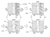
- FIG. 2 is a conceptual diagram illustrating a method for removing residual water in a fuel cell in accordance with a preferred embodiment of the present invention.
- dry gas at a relative humidity of 0% is supplied to an anode through a bipolar plate, and fully humidified gas at a relative humidity of 100% is supplied to a cathode.
- an anode GDL 101 is dried by the dry gas, and subsequently, the water of a cathode GDL 103 passes through the membrane 102 to saturate the anode GDL 101 dried by the dry gas, and thereby the humidity of the membrane is maintained while there is a reduction in water content in the fuel cell.
- an amount of the fully humidified gas supplied to the cathode may be configured to be three times of an amount of the dry gas supplied to the anode.
- FIG. 3 is a conceptual diagram illustrating a method for removing residual water in a fuel cell in accordance with a comparative embodiment.
- fully humidified gas is supplied to the anode GDL 101 through the bipolar plate, and dry gas is supplied to the cathode GDL 103 . Then, the cathode GDL 103 is dried by the dry gas, and water of the anode GDL 101 saturated by the fully humidified gas moves through the membrane 102 to the cathode GDL.
- an amount of the dry gas supplied to the cathode is configured to be three times of an amount of the fully humidified gas supplied to the anode. It means that removal rate of the water at the cathode side would be substantially three times of supplying rate of the water from the anode side, which results in excessive removal of water content from the membrane along with decrease of total water amount in the cell. Therefore, unlike to the preferred embodiment of FIG. 2 , the membrane is excessively dried up and the endurance thereof is deteriorated.
- the water content in the fuel cell may vary depending on operation range of the fuel cell, relative humidity of the fuel gases, and flow rate of the fuel gases. Specifically, if the fuel cell operates in high-current area, the electro-chemical reaction is actively increased, and water generated in the fuel cell increases accordingly. However, since catalysts layer of the fuel cell are also heated up along the intensive electro-chemical reaction, the generated water at the catalyst layer is soon vaporized and moved toward the GDLs. In this instance, if the fuel gases supplied to electrodes are dry, the vaporized water is then removed from the fuel cell. Namely, before purging process, the water content in the fuel cell can be adjusted by controlling operation range of the fuel cell and relative humidity of the fuel gases even during operation of the fuel cell.
- operating status of the fuel cell before purging is also much important to control the water content in the fuel cell, as well as purging process itself.
- Purge gases were supplied to the anode and the cathode of a fuel cell having an active area of 250 cm 2 by varying the relative humidities of purge gases to the anode and the cathode (i.e., 100%/100%, 0%/100%, 100%/0%, and 50%/50%, respectively) after operation with various flow rate and relative humidity of fuel gas at various current conditions.
- the change in water content of the fuel cell was investigated using neutron imaging and the change in ion conductivity of the membrane 102 was measured with a milliohm meter After operating the cell at each condition (which is the pre-purge condition), loads were turned off at each current level, and the flow rate of purge gases was maintained constant for 5 minutes (purging for 5 minutes).
- FIG. 4 is a graph comparing the membrane resistance and the residual water content in the fuel cell at relative humidities of 100%/100% at the anode and cathode with respect to current density.
- the left vertical axis represents the water content in the fuel cell
- the right vertical axis represents the resistance of the membrane 102
- the upper two lines indicate that the water content in the fuel cell is reduced before and after purging
- the lower line indicates that there is no change in resistance of the membrane 102 .
- FIG. 5 is a graph comparing the membrane resistance and the residual water content in the fuel cell at relative humidities of 0%/100% at the anode and cathode with respect to current density.
- the resistance of the membrane 102 was increased to 0.0377 Ohm/cm 2 after purging at the maximum flow rate (1 A/cm 2 ), and the water content in the fuel cell was significantly reduced to 4.77 mg/cm 2 .
- the increase in the resistance of the membrane 102 compared to the reduction in the water content in the fuel cell was very small.
- FIG. 6 is a graph comparing the membrane resistance and the residual water content in the fuel cell at relative humidities of 100%/0% at the anode and cathode with respect to current density.
- FIG. 7 is a graph comparing the membrane resistance and the residual water content in the fuel cell at relative humidities of 50%/50% at the anode and cathode with respect to current density.
- the water content in the fuel cell was slightly reduced to 5.4 mg/cm 2 after purging at a low flow rate (0.64 A/cm 2 ), and the resistance of the membrane 102 was increased to 0.065 ohm/cm 2 . As a result, a considerable amount of water was removed from the membrane 102 .
- FIG. 8 is a graph showing a change in water content before and after purging at a flow rate of 1 A/cm 2 under various purging conditions
- FIG. 9 is a graph showing a change in resistance of the membrane before and after purging at the same flow rate as FIG. 8 under various purging conditions.
- FIG. 10 is a graph showing a change in resistance of the membrane 102 with respect to the water content in the fuel cell under various purging conditions
- FIG. 11 is a graph showing a change in water content ( ⁇ mol water/mol SO 3 H) in the membrane 102 with respect to the water content in the fuel cell under various purging conditions.
- the water content in the membrane ( ⁇ ) will be 7.5 by purge with RH0/100, 5.8 with RH100/0, and 4.5 with RH50/50 as shown in FIG. 11 .
- the method for removing residual water in the fuel cell of the present invention it is possible to effectively remove residual water in the fuel cell and maintain the relative humidity of the membrane, by controlling the relative humidities of purge gases to selectively control the water content in the fuel cell and the water content in the membrane, thus ensuring the durability of the membrane.
Landscapes
- Life Sciences & Earth Sciences (AREA)
- Engineering & Computer Science (AREA)
- Manufacturing & Machinery (AREA)
- Sustainable Development (AREA)
- Sustainable Energy (AREA)
- Chemical & Material Sciences (AREA)
- Chemical Kinetics & Catalysis (AREA)
- Electrochemistry (AREA)
- General Chemical & Material Sciences (AREA)
- Fuel Cell (AREA)
Abstract
Description
| 101: | anode GDL | ||
| 102: | membrane | ||
| 103: | cathode GDL | ||
Claims (4)
Priority Applications (2)
| Application Number | Priority Date | Filing Date | Title |
|---|---|---|---|
| US12/544,816 US8685584B2 (en) | 2009-08-20 | 2009-08-20 | Method for removing residual water from fuel cell |
| KR1020090087253A KR101550930B1 (en) | 2009-08-20 | 2009-09-15 | Method for removing residual water from fuel cell |
Applications Claiming Priority (1)
| Application Number | Priority Date | Filing Date | Title |
|---|---|---|---|
| US12/544,816 US8685584B2 (en) | 2009-08-20 | 2009-08-20 | Method for removing residual water from fuel cell |
Publications (2)
| Publication Number | Publication Date |
|---|---|
| US20110045365A1 US20110045365A1 (en) | 2011-02-24 |
| US8685584B2 true US8685584B2 (en) | 2014-04-01 |
Family
ID=43605625
Family Applications (1)
| Application Number | Title | Priority Date | Filing Date |
|---|---|---|---|
| US12/544,816 Active 2031-02-24 US8685584B2 (en) | 2009-08-20 | 2009-08-20 | Method for removing residual water from fuel cell |
Country Status (2)
| Country | Link |
|---|---|
| US (1) | US8685584B2 (en) |
| KR (1) | KR101550930B1 (en) |
Families Citing this family (6)
| Publication number | Priority date | Publication date | Assignee | Title |
|---|---|---|---|---|
| US9368817B2 (en) * | 2009-10-16 | 2016-06-14 | GL Global Technology Operations LLC | In-situ fuel cell stack reconditioning |
| CN111864238B (en) * | 2020-06-28 | 2021-12-21 | 江苏大学 | A kind of detection device and control method of water content in fuel cell |
| CN112952160A (en) * | 2021-01-29 | 2021-06-11 | 上海神力科技有限公司 | Method for determining relation between water content of membrane and membrane internal resistance |
| CN113328123B (en) * | 2021-05-20 | 2022-08-30 | 东风汽车集团股份有限公司 | Fuel cell stack shell purging device and control method |
| CN114447375B (en) * | 2021-12-31 | 2024-02-13 | 东方电气(成都)氢燃料电池科技有限公司 | A fuel cell system shutdown purging method |
| CN116314946A (en) * | 2023-03-28 | 2023-06-23 | 上海捷氢科技股份有限公司 | Fuel cell system residual water purging system and method |
Citations (7)
| Publication number | Priority date | Publication date | Assignee | Title |
|---|---|---|---|---|
| JP2004039526A (en) | 2002-07-05 | 2004-02-05 | Nissan Motor Co Ltd | Fuel cell system |
| JP2004179086A (en) | 2002-11-28 | 2004-06-24 | Nissan Motor Co Ltd | Polymer electrolyte fuel cell system and method of operating the same |
| JP2005100775A (en) | 2003-09-24 | 2005-04-14 | Nissan Motor Co Ltd | Fuel cell power generation system |
| US20060121322A1 (en) * | 2004-12-02 | 2006-06-08 | Haas Herwig R | Systems and methods for fuel cell shutdown |
| US20060222924A1 (en) * | 2003-05-15 | 2006-10-05 | Naoya Matsuoka | Prevention of flooding of fuel cell stack |
| KR20080043821A (en) | 2005-08-11 | 2008-05-19 | 퓨얼 셀 에너지, 인크 | Control assembly to control the fuel cell system during shutdown and restart |
| US20100190076A1 (en) * | 2009-01-23 | 2010-07-29 | Gm Global Technology Operations, Inc. | Two stage, hfr-free freeze preparation shutdown strategy |
-
2009
- 2009-08-20 US US12/544,816 patent/US8685584B2/en active Active
- 2009-09-15 KR KR1020090087253A patent/KR101550930B1/en active Active
Patent Citations (7)
| Publication number | Priority date | Publication date | Assignee | Title |
|---|---|---|---|---|
| JP2004039526A (en) | 2002-07-05 | 2004-02-05 | Nissan Motor Co Ltd | Fuel cell system |
| JP2004179086A (en) | 2002-11-28 | 2004-06-24 | Nissan Motor Co Ltd | Polymer electrolyte fuel cell system and method of operating the same |
| US20060222924A1 (en) * | 2003-05-15 | 2006-10-05 | Naoya Matsuoka | Prevention of flooding of fuel cell stack |
| JP2005100775A (en) | 2003-09-24 | 2005-04-14 | Nissan Motor Co Ltd | Fuel cell power generation system |
| US20060121322A1 (en) * | 2004-12-02 | 2006-06-08 | Haas Herwig R | Systems and methods for fuel cell shutdown |
| KR20080043821A (en) | 2005-08-11 | 2008-05-19 | 퓨얼 셀 에너지, 인크 | Control assembly to control the fuel cell system during shutdown and restart |
| US20100190076A1 (en) * | 2009-01-23 | 2010-07-29 | Gm Global Technology Operations, Inc. | Two stage, hfr-free freeze preparation shutdown strategy |
Also Published As
| Publication number | Publication date |
|---|---|
| US20110045365A1 (en) | 2011-02-24 |
| KR101550930B1 (en) | 2015-09-08 |
| KR20110019688A (en) | 2011-02-28 |
Similar Documents
| Publication | Publication Date | Title |
|---|---|---|
| US8323415B2 (en) | Fast recycling process for ruthenium, gold and titanium coatings from hydrophilic PEM fuel cell bipolar plates | |
| US8685584B2 (en) | Method for removing residual water from fuel cell | |
| US20060216571A1 (en) | Metal oxide based hydrophilic coatings for PEM fuel cell bipolar plates | |
| US20110195324A1 (en) | Methods and processes to recover voltage loss of pem fuel cell stack | |
| WO2012017474A1 (en) | Fuel cell system | |
| US9368817B2 (en) | In-situ fuel cell stack reconditioning | |
| US10290888B2 (en) | Method of operating fuel cell system with performance recovery control | |
| US9178233B2 (en) | Smart in-vehicle reactive recovery strategy | |
| JP5581880B2 (en) | Fuel cell system | |
| US20120123620A1 (en) | Purging device and method for improving cold-startability of fuel cell | |
| KR100974734B1 (en) | Hydrogen purge device of fuel cell vehicle | |
| US20090311560A1 (en) | Method for reverse activation of fuel cell | |
| JP2021174670A (en) | Fuel cell system | |
| US11502315B2 (en) | System and method for purging condensate water and hydrogen of fuel cell stack | |
| US20230299321A1 (en) | Method for a frost start of a fuel cell device, fuel cell device and motor vehicle having a fuel cell device | |
| CN101714643B (en) | Material design to enable high mid-temperature performance of a fuel cell with ultrathin electrodes | |
| JP5319160B2 (en) | Fuel cell system | |
| CN114628746B (en) | Fuel cell system | |
| JP2021166152A (en) | Fuel cell system | |
| KR20080046025A (en) | Operating fluid discharge device of fuel cell stack and its control method | |
| US8431275B2 (en) | Water management of PEM fuel cell stacks using surface active agents | |
| US11764371B2 (en) | Fuel cell system | |
| US11515548B2 (en) | Fuel cell system | |
| US20230352699A1 (en) | Catalyst for fuel cell | |
| KR101558355B1 (en) | Method of purging flooding and impurities in hydrogen electrode of fuel cell system |
Legal Events
| Date | Code | Title | Description |
|---|---|---|---|
| AS | Assignment |
Owner name: HYUNDAI MOTOR COMPANY, KOREA, REPUBLIC OF Free format text: ASSIGNMENT OF ASSIGNORS INTEREST;ASSIGNORS:CHO, KYU TAEK;YOON, JONG JIN;LEE, JONG HYUN;AND OTHERS;REEL/FRAME:023126/0156 Effective date: 20090303 Owner name: THE PENN STATE RESEARCH FOUNDATION, PENNSYLVANIA Free format text: ASSIGNMENT OF ASSIGNORS INTEREST;ASSIGNORS:CHO, KYU TAEK;YOON, JONG JIN;LEE, JONG HYUN;AND OTHERS;REEL/FRAME:023126/0156 Effective date: 20090303 |
|
| AS | Assignment |
Owner name: THE PENN STATE RESEARCH FOUNDATION, PENNSYLVANIA Free format text: ASSIGNMENT OF ASSIGNORS INTEREST;ASSIGNORS:CHO, KYU TAEK;YOON, JONG JIN;LEE, JONG HYUN;AND OTHERS;REEL/FRAME:023133/0037 Effective date: 20090303 Owner name: HYUNDAI MOTOR COMPANY, KOREA, REPUBLIC OF Free format text: ASSIGNMENT OF ASSIGNORS INTEREST;ASSIGNORS:CHO, KYU TAEK;YOON, JONG JIN;LEE, JONG HYUN;AND OTHERS;REEL/FRAME:023133/0037 Effective date: 20090303 |
|
| FEPP | Fee payment procedure |
Free format text: PAYOR NUMBER ASSIGNED (ORIGINAL EVENT CODE: ASPN); ENTITY STATUS OF PATENT OWNER: LARGE ENTITY |
|
| STCF | Information on status: patent grant |
Free format text: PATENTED CASE |
|
| MAFP | Maintenance fee payment |
Free format text: PAYMENT OF MAINTENANCE FEE, 4TH YEAR, LARGE ENTITY (ORIGINAL EVENT CODE: M1551) Year of fee payment: 4 |
|
| MAFP | Maintenance fee payment |
Free format text: PAYMENT OF MAINTENANCE FEE, 8TH YEAR, LARGE ENTITY (ORIGINAL EVENT CODE: M1552); ENTITY STATUS OF PATENT OWNER: LARGE ENTITY Year of fee payment: 8 |