US8678564B2 - Inkjet print head - Google Patents
Inkjet print head Download PDFInfo
- Publication number
- US8678564B2 US8678564B2 US13/829,090 US201313829090A US8678564B2 US 8678564 B2 US8678564 B2 US 8678564B2 US 201313829090 A US201313829090 A US 201313829090A US 8678564 B2 US8678564 B2 US 8678564B2
- Authority
- US
- United States
- Prior art keywords
- chamber
- pressure wave
- nozzle
- actuation chamber
- print head
- Prior art date
- Legal status (The legal status is an assumption and is not a legal conclusion. Google has not performed a legal analysis and makes no representation as to the accuracy of the status listed.)
- Expired - Fee Related
Links
Images


Classifications
-
- B—PERFORMING OPERATIONS; TRANSPORTING
- B41—PRINTING; LINING MACHINES; TYPEWRITERS; STAMPS
- B41J—TYPEWRITERS; SELECTIVE PRINTING MECHANISMS, i.e. MECHANISMS PRINTING OTHERWISE THAN FROM A FORME; CORRECTION OF TYPOGRAPHICAL ERRORS
- B41J2/00—Typewriters or selective printing mechanisms characterised by the printing or marking process for which they are designed
- B41J2/005—Typewriters or selective printing mechanisms characterised by the printing or marking process for which they are designed characterised by bringing liquid or particles selectively into contact with a printing material
- B41J2/01—Ink jet
- B41J2/135—Nozzles
- B41J2/14—Structure thereof only for on-demand ink jet heads
- B41J2/14201—Structure of print heads with piezoelectric elements
- B41J2/14233—Structure of print heads with piezoelectric elements of film type, deformed by bending and disposed on a diaphragm
-
- B—PERFORMING OPERATIONS; TRANSPORTING
- B41—PRINTING; LINING MACHINES; TYPEWRITERS; STAMPS
- B41J—TYPEWRITERS; SELECTIVE PRINTING MECHANISMS, i.e. MECHANISMS PRINTING OTHERWISE THAN FROM A FORME; CORRECTION OF TYPOGRAPHICAL ERRORS
- B41J2202/00—Embodiments of or processes related to ink-jet or thermal heads
- B41J2202/01—Embodiments of or processes related to ink-jet heads
- B41J2202/12—Embodiments of or processes related to ink-jet heads with ink circulating through the whole print head
Definitions
- the present invention generally pertains to inkjet printing and in particular to a print head assembly.
- ink is arranged in a pressure chamber.
- the pressure chamber has an ink inlet at a first side of the pressure chamber and a nozzle at a second side, opposite of the first side.
- the pressure chamber ends at the nozzle. No ink may flow beyond the nozzle other than by being jetted through the nozzle. So, for example if no ink is jetted, dirt and/or air bubbles may become trapped in the pressure chamber, near the nozzle. With a large amount of dirt or with large air bubbles, or other similar irregularities in the pressure chamber, a droplet ejection may become disturbed or the nozzle may become blocked completely.
- a continuous flow of ink passes through an ink channel.
- an actuator for example a pi ⁇ zo actuator or a heating element for thermal actuation as well known in the art, is arranged opposite a nozzle arranged at a second, opposite side of the ink channel. Due to the continuous flow, there is less chance that an air bubble or dirt becomes trapped near the nozzle as it may flow with the ink through the ink channel towards a central reservoir.
- a filter means may be provided for removing dirt and/or air from the ink coming from the ink channel returning to the reservoir. Thus, air bubble free and dirt free ink may be re-introduced in the ink channel.
- a disadvantage of the latter, known print head is the fact that it is not suited to be used in combination with certain inks, for example high viscosity inks, since an actuation efficiency, that is an actuation pressure generated by the actuator, is significantly decreased. More in particular, in the known continuous flow print head, the actuation efficiency is about 50% lower compared to the above first mentioned print head (having the nozzle arranged at an end of the pressure chamber).
- a print head comprising at least one actuation chamber, wherein a main part of the actuation chamber substantially extends in a first direction.
- Each actuation chamber is associated with a respective piezo actuator, a chamber inlet, a nozzle and a chamber outlet.
- the piezo actuator is arranged to generate a pressure wave in the main part of the actuation chamber, the pressure wave propagating in the first direction.
- the chamber inlet is arranged at a first end of the actuation chamber.
- the nozzle is arranged in fluid communication with the associated actuation chamber such that a droplet may be expelled through the nozzle upon generation of the pressure wave in the associated actuation chamber.
- the chamber outlet is arranged at a second end of the associated actuation chamber.
- the print head further comprises a reservoir in fluid communication with the chamber inlet and the chamber outlet of the at least one actuation chamber and further comprises a pump means for pumping ink from the reservoir, through the chamber inlet, through the actuation chamber, through the chamber outlet and into said reservoir.
- the inkjet print head according to the present invention comprises a means for reflecting the pressure wave which means is provided at the second end of the actuation chamber.
- Suitably reflecting the pressure wave is advantageous for generating a sufficient pressure at the nozzle for expelling the droplet, as is explained hereinbelow in more detail.
- an efficiency decrease of only 10% or less is obtainable.
- multiple, i.e. at least two, actuation chambers and associated parts are coupled to a single reservoir.
- the means for reflecting the pressure wave comprises a compliance provided at the second end of the actuation chamber.
- the compliance e.g. provided by an elastic member, ensures that a reflection of the pressure wave occurs, as is known in the art.
- a suitably selected compliance will provide a suitable reflection.
- a nozzle plate provides the nozzles of the print head and the nozzle plate is selected to be flexible and elastic. When arranged suitably, the nozzle plate provides the compliance.
- a cross-section of the actuation chamber just upstream of the chamber outlet is substantially smaller than the cross-section of an ink channel just downstream of the chamber outlet.
- Such a change in cross-section acts on a pressure wave as a kind of open end of the actuation chamber.
- a pressure wave will mainly reflect (a small part of the pressure wave may propagate through the chamber outlet into the ink channel).
- a suitable selection of cross-sections allows to control the ratio of the reflected part and the propagating part of the pressure wave.
- a first pressure wave is generated by the piezo actuator, the first pressure wave propagating towards the second end of the actuation chamber and, after reflection at the second end, propagating towards the nozzle. Further, a subsequent second pressure wave is generated by the piezo actuator, wherein the second pressure wave also propagates towards the second end.
- the dimensions of the actuator chamber and the timing of the second pressure wave relative to the first pressure wave are selected such that (i) the reflection of the first pressure wave and (ii) the second pressure wave arrive at the nozzle at the same time such that a large pressure is provided by the sum of the reflection of the first pressure wave and the second pressure wave.
- a suitably high pressure is generated at the nozzle, resulting in expelling a droplet through the nozzle.
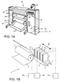
- FIG. 1A shows a perspective view of an image forming apparatus
- FIG. 1B schematically illustrates an inkjet printing assembly
- FIG. 2A schematically illustrates a first simplified prior art inkjet print head
- FIG. 2B schematically illustrates a second simplified prior art inkjet print head
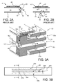
- FIG. 3A schematically shows a perspective view of a cross-section of a first embodiment of an inkjet print head in accordance with the present invention
- FIG. 3B schematically shows a side view of the print head shown in FIG. 3A ;
- FIG. 3C schematically illustrates an actuation chamber of the print head shown in FIG. 3A ;
- FIG. 4 schematically shows a perspective view of a cross-section of a second embodiment of an inkjet print head in accordance with the present invention.
- FIG. 1A shows an image forming apparatus 36 , wherein printing is achieved using a wide format inkjet printer.
- the wide-format image forming apparatus 36 comprises a housing 26 , wherein the printing assembly, for example the ink jet printing assembly shown in FIG. 1B is placed.
- the image forming apparatus 36 also comprises a storage means for storing image receiving member 28 , 30 , a delivery station to collect the image receiving member 28 , 30 after printing and storage means for marking material 20 .
- the delivery station is embodied as a delivery tray 32 .
- the delivery station may comprise processing means for processing the image receiving member 28 , 30 after printing, e.g. a folder or a puncher.
- the wide-format image forming apparatus 36 furthermore comprises means for receiving print jobs and optionally means for manipulating print jobs. These means may include a user interface unit 24 and/or a control unit 34 , for example a computer.
- Images are printed on a image receiving member, for example paper, supplied by a roll 28 , 30 .
- the roll 28 is supported on the roll support R 1
- the roll 30 is supported on the roll support R 2 .
- cut sheet image receiving members may be used instead of rolls 28 , 30 of image receiving member.
- Printed sheets of the image receiving member, cut off from the roll 28 , 30 are deposited in the delivery tray 32 .
- Each one of the marking materials for use in the printing assembly are stored in four containers 20 arranged in fluid connection with the respective print heads for supplying marking material to said print heads.
- the local user interface unit 24 is integrated to the print engine and may comprise a display unit and a control panel. Alternatively, the control panel may be integrated in the display unit, for example in the form of a touch-screen control panel.
- the local user interface unit 24 is connected to a control unit 34 placed inside the printing apparatus 36 .
- the control unit 34 for example a computer, comprises a processor adapted to issue commands to the print engine, for example for controlling the print process.
- the image forming apparatus 36 may optionally be connected to a network N.
- the connection to the network N is diagrammatically shown in the form of a cable 22 , but nevertheless, the connection could be wireless.
- the image forming apparatus 36 may receive printing jobs via the network. Further, optionally, the controller of the printer may be provided with a USB port, so printing jobs may be sent to the printer via this USB port.
- FIG. 1B shows an ink jet printing assembly 3 .
- the ink jet printing assembly 3 comprises supporting means for supporting an image receiving member 2 .
- the supporting means are shown in FIG. 1B as a platen 1 , but alternatively, the supporting means may be a flat surface.
- the platen 1 is a rotatable drum, which is rotatable about its axis as indicated by arrow A.
- the supporting means may be optionally provided with suction holes for holding the image receiving member in a fixed position with respect to the supporting means.
- the ink jet printing assembly 3 comprises print heads 4 a - 4 d , mounted on a scanning print carriage 5 .
- the scanning print carriage 5 is guided by suitable guiding means 6 , 7 to move in reciprocation in the main scanning direction B.
- Each print head 4 a - 4 d comprises an orifice surface 9 , which orifice surface 9 is provided with at least one orifice 8 .
- the print heads 4 a - 4 d are configured to eject droplets of marking material onto the image receiving member 2 .
- the platen 1 , the carriage 5 and the print heads 4 a - 4 d are controlled by suitable controlling means 10 a , 10 b and 10 c , respectively.
- the image receiving member 2 may be a medium in web or in sheet form and may be composed of e.g. paper, cardboard, label stock, coated paper, plastic or textile. Alternatively, the image receiving member 2 may also be an intermediate member, endless or not. Examples of endless members, which may be moved cyclically, are a belt or a drum. The image receiving member 2 is moved in the sub-scanning direction A by the platen 1 along four print heads 4 a - 4 d provided with a fluid marking material.
- a scanning print carriage 5 carries the four print heads 4 a - 4 d and may be moved in reciprocation in the main scanning direction B parallel to the platen 1 , such as to enable scanning of the image receiving member 2 in the main scanning direction B. Only four print heads 4 a - 4 d are depicted for demonstrating the invention. In practice an arbitrary number of print heads may be employed. In any case, at least one print head 4 a - 4 d per color of marking material is placed on the scanning print carriage 5 . For example, for a black-and-white printer, at least one print head 4 a - 4 d , usually containing black marking material is present.
- a black-and-white printer may comprise a white marking material, which is to be applied on a black image-receiving member 2 .
- a full-color printer containing multiple colors, at least one print head 4 a - 4 d for each of the colors, usually black, cyan, magenta and yellow is present.
- black marking material is used more frequently in comparison to differently colored marking material. Therefore, more print heads 4 a - 4 d containing black marking material may be provided on the scanning print carriage 5 compared to print heads 4 a - 4 d containing marking material in any of the other colors.
- the print head 4 a - 4 d containing black marking material may be larger than any of the print heads 4 a - 4 d , containing a differently colored marking material.
- the carriage 5 is guided by guiding means 6 , 7 .
- These guiding means 6 , 7 may be rods as depicted in FIG. 1B .
- the rods may be driven by suitable driving means (not shown).
- the carriage 5 may be guided by other guiding means, such as an arm being able to move the carriage 5 .
- Another alternative is to move the image receiving material 2 in the main scanning direction B.
- Each print head 4 a - 4 d comprises an orifice surface 9 having at least one orifice 8 , in fluid communication with a pressure chamber containing fluid marking material provided in the print head 4 a - 4 d .
- a number of orifices 8 is arranged in a single linear array parallel to the sub-scanning direction A.
- Eight orifices 8 per print head 4 a - 4 d are depicted in FIG. 1B , however obviously in a practical embodiment several hundreds of orifices 8 may be provided per print head 4 a - 4 d , optionally arranged in multiple arrays. As depicted in FIG.
- the respective print heads 4 a - 4 d are placed parallel to each other such that corresponding orifices 8 of the respective print heads 4 a - 4 d are positioned in-line in the main scanning direction B.
- a line of image dots in the main scanning direction B may be formed by selectively activating up to four orifices 8 , each of them being part of a different print head 4 a - 4 d .
- This parallel positioning of the print heads 4 a - 4 d with corresponding in-line placement of the orifices 8 is advantageous to increase productivity and/or improve print quality.
- multiple print heads 4 a - 4 d may be placed on the print carriage adjacent to each other such that the orifices 8 of the respective print heads 4 a - 4 d are positioned in a staggered configuration instead of in-line. For instance, this may be done to increase the print resolution or to enlarge the effective print area, which may be addressed in a single scan in the main scanning direction.
- the image dots are formed by ejecting droplets of marking material from the orifices 8 .
- marking material Upon ejection of the marking material, some marking material may be spilled and stay on the orifice surface 9 of the print head 4 a - 4 d .
- the ink present on the orifice surface 9 may negatively influence the ejection of droplets and the placement of these droplets on the image receiving member 2 . Therefore, it may be advantageous to remove excess of ink from the orifice surface 9 .
- the excess of ink may be removed for example by wiping with a wiper and/or by application of a suitable anti-wetting property of the surface, e.g. provided by a coating.
- FIG. 2A shows an actuation chamber 44 as a part of a prior art inkjet print head 4 .
- the actuation chamber 44 is formed by a main body 41 and a nozzle plate 42 , having arranged therein a nozzle 45 .
- a piezo actuator element 43 is arranged on a side wall of the actuation chamber 44 such that upon actuation the wall deforms and a pressure wave is generated in the actuation chamber 44 .
- the pressure wave is generated such that an actuation pressure is provided near the nozzle 45 in an actuation direction 48 , parallel to a direction in which the actuator 43 extends, resulting in expelling droplets 49 .
- a dirt particle or an air bubble 47 may become trapped in the nozzle 45 or the actuation chamber 44 .
- An air bubble 47 in the actuation chamber 44 damps any pressure wave generated in the actuation chamber 44 resulting in a decreased pressure near the nozzle 45 and hence in deteriorated droplet formation.
- a dirt particle in or near the nozzle 45 evidently also result in deteriorated droplet formation.
- a dirt particle or air bubble 47 however cannot escape and may therefore in a worst case result in a permanently unusable actuation chamber 44 and nozzle 45 .
- FIG. 2B another known inkjet print head 4 is shown in a simplified drawing.
- An actuation chamber 44 is formed in a main body 41 , wherein a nozzle 45 is arranged.
- an actuator 43 is arranged.
- the actuator 43 is may be a thermistor for thermal actuation: a sudden local heating of the ink by the actuator 43 results in a bubble of vapor. Vapor requires more volume than the original liquid ink and consequently the pressure in the ink increases in an actuation direction 48 perpendicular to a direction in which the actuator 43 extends and as a result a droplet 49 may be expelled through the oppositely arranged nozzle 45 .
- the actuator 43 may be a pi ⁇ zo actuator (i.e. an electromechanical transducer), which increases and/or reduces a volume of the pressure chamber 44 when supplied with a driving voltage. The volume change results in a pressure wave that may result in a droplet being expelled through the nozzle 45 .
- a pi ⁇ zo actuator i.e. an electromechanical transducer
- a dirt particle or an air bubble 47 may become trapped.
- the ink continuously flows in a flow direction 46 .
- the air bubble 47 may be carried by the ink away from the nozzle 45 and consequently there is a smaller chance that the nozzle 45 may be unusable due to a blockage of the nozzle 45 .
- a print head having a thermal actuation is only suitable for use with solvent based inks, such as aqueous inks, of which the solvent may quickly vaporize.
- solvent based inks such as aqueous inks, of which the solvent may quickly vaporize.
- a low viscosity of the ink is required, since only a relatively small pressure can be generated near the nozzle 45 in the actuation direction 48 . A significant part of the generated pressure is lost in the direction perpendicular to the actuation direction 48 , i.e. parallel to the flow direction 46 .
- an inkjet print head 4 as shown in FIG. 2A is known and available, but a print head providing a continuous flow of ink through the actuation chamber 44 and along the nozzle 45 is not available due to such pressure loss.
- FIG. 3A-3C illustrate an embodiment of a print head 50 in accordance with the present invention providing an actuation method in accordance with the print head 4 shown in FIG. 2A and providing a continuous flow of ink through the actuation chamber 54 ( FIG. 3A ), 54 a - 54 e ( FIG. 3C ).
- the inkjet print head 50 has a main body 51 of any suitable material. For example, graphite or silicon may be used but also other materials suited for fine mechanical processing may be employed.
- a number of piezo actuators 53 are arranged on an actuator support element 52 . Each actuator 53 is associated with one of a number of actuator chambers 54 such that upon actuation a droplet may be expelled through an associated nozzle 60 .
- a suitable flexible sheet material 58 is arranged between the respective actuators 53 and the actuator chambers 54 .
- the print head 50 is provided with a first ink inlet 55 a , a second ink inlet 55 b and an ink outlet 56 .
- An ink flow path is arranged in the print head 50 starting at the first ink inlet 55 a , flowing through a passage as indicated by an arrow 57 a towards an actuator chamber 54 as indicated by an arrow 57 b , through the actuator chamber 54 as indicated by an arrow 57 c and subsequently through a first outlet passage 56 a as indicated by an arrow 57 d towards the ink outlet 56 as indicated by an arrow 57 e.
- a similar second ink flow path starts at the second ink inlet 55 b .
- a second actuator support element and a second number of piezo actuators is not shown, but may in practice be present.
- only a single flow path may be provided by omitting the second flow path.
- a back side of the print head 50 is shown.
- the back side is opposite to a front side, wherein the front side comprises the nozzles 60 .
- the back side comprises the first and the second ink inlets 55 a , 55 b and the ink outlet 56 .
- the first ink inlet 55 a and the second ink inlet 55 b are each in fluid connection with a main ink inlet terminal 59 a and the ink outlet 56 is in fluid communication with a main ink outlet 59 b .
- an ink reservoir and a pump means may be provided such that ink may be pumped from such an ink reservoir to the main ink inlet 59 a , through the inkjet print head 50 and through the main ink outlet 59 b back to the reservoir in a continuous flow.
- the actuation chamber 54 comprises a chamber inlet 54 a , a main part 54 b , a coupling part 54 c , a drain part 54 d having a length L and a chamber outlet 54 e .
- Ink may enter the actuation chamber 54 at the chamber inlet 54 a .
- the chamber inlet 54 a may have the same characteristics as a chamber inlet of the known print head 4 shown in FIG. 2A .
- the chamber inlet 54 a may be configured to substantially reflect a pressure wave propagating in a direction parallel to a direction in which the actuator 53 extends.
- the piezo actuator 53 may be driven to generate a pressure wave in the main part 54 b of the actuation chamber 54 .
- the pressure wave may propagate through the main part 54 b and through the coupling part 54 c towards the nozzle 60 and even further through the drain part 54 d .
- the pressure wave is substantially reflected back towards the nozzle 60 .
- the actuator 53 is first driven to increase a volume of the main part 54 b , thereby generating a first propagating pressure wave. After a predetermined period of time, the actuator 53 is driven to its original position, thereby decreasing the volume of the main part 54 b and generating a second pressure wave.
- the first pressure wave having been reflected at the chamber outlet 54 e returns near the nozzle 60 at the same time that the second pressure wave arrives near the nozzle 60 , thereby generating sufficient pressure near the nozzle 60 for expelling a droplet through the nozzle 60 with a sufficient size and speed.
- the flexible sheet material 58 ( FIG. 3A ) provides a suitable compliance, as known from and used in a known inkjet print head.
- a similar compliance may be provided at the chamber outlet 54 e .
- such a compliance is provided by a flexible sheet material arranged over the drain part 54 d of the actuation chamber 54 and having arranged therein the nozzle 60 (such a sheet material is shown in FIG. 4 and is described and elucidated in the description relating to FIG. 4 ).
- providing a compliance at or near the nozzle may also be advantageously employed in another print head design in order to enable sufficient pressure generation near the nozzle for jetting a high viscosity fluid.
- a large impedance may be provided as well known in the art.
- suitable reflection of the pressure wave at the chamber outlet 54 e may be provided due to a cross-section of the ink outlet passages, e.g. the first ink outlet passage 56 a and a second ink outlet passage 56 b , that is significantly larger than a cross-section of the drain part 54 d of the actuation chamber 54 .
- FIG. 4 shows another embodiment of a print head 70 according to the present invention.
- the print head 70 comprises a main body 71 , an actuator support element 72 , an actuator 73 , an actuation chamber comprising a chamber inlet 74 a , a main part 74 b , a coupling part 74 c , a drain part 74 d and a chamber outlet 74 e .
- the print head 70 further comprises a nozzle plate 75 having nozzles 76 arranged therein, each nozzle being associated with an actuation chamber, and a flexible sheet member 78 covering the main part 74 b of the actuation chamber.
- Ink may be supplied through a first and a second ink inlet 81 a , 81 b and ink may leave the print head 70 through an ink outlet 82 .
- the print head 70 is additionally provided with a nozzle plate support element 71 a.
- the nozzle plate 75 is, as above mentioned, made of a flexible sheet material in which the nozzles 76 are provided.
- the flexible nozzle plate 75 covers the drain part 74 d of the actuation chamber, thereby providing a suitable compliance as described in relation to FIG. 3C .
- a support surface area of the nozzle plate support element 71 a may be determined such that the compliance provided by the flexible nozzle plate 75 is suitable. For example, if the support surface area is small, a length of an unsupported part of the flexible sheet is large and the compliance is large. Increasing the support surface area results in a decrease of the unsupported part of the flexible sheet and hence in a decrease of the compliance. Further, the nozzle plate support element 71 a may assist in reducing cross talk as a result of a part of a pressure wave passing beyond the chamber outlet 74 e.
- FIG. 3A no nozzle plate is shown.
- a nozzle plate may be made of a flexible sheet material as present in the embodiment shown in FIG. 4 .
- the nozzle plate may be made of a rigid material or any other suitable material.
- the nozzle plate formed as a flexible sheet is made of a polyimide sheet material such as Upilex®.
- the terms and phrases used herein are not intended to be limiting; but rather, to provide an understandable description of the invention.
- the terms “a” or “an”, as used herein, are defined as one or more than one.
- the term plurality, as used herein, is defined as two or more than two.
- the term another, as used herein, is defined as at least a second or more.
- the terms including and/or having, as used herein, are defined as comprising (i.e., open language).
- the term coupled, as used herein, is defined as connected, although not necessarily directly.
Landscapes
- Particle Formation And Scattering Control In Inkjet Printers (AREA)
- Ink Jet (AREA)
Abstract
Description
Claims (14)
Applications Claiming Priority (4)
| Application Number | Priority Date | Filing Date | Title |
|---|---|---|---|
| EP10185813 | 2010-10-01 | ||
| EP10185813.2 | 2010-10-01 | ||
| EP10185813 | 2010-10-01 | ||
| PCT/EP2011/066187 WO2012041729A1 (en) | 2010-10-01 | 2011-09-19 | Inkjet print head |
Related Parent Applications (1)
| Application Number | Title | Priority Date | Filing Date |
|---|---|---|---|
| PCT/EP2011/066187 Continuation WO2012041729A1 (en) | 2010-10-01 | 2011-09-19 | Inkjet print head |
Publications (2)
| Publication Number | Publication Date |
|---|---|
| US20130194351A1 US20130194351A1 (en) | 2013-08-01 |
| US8678564B2 true US8678564B2 (en) | 2014-03-25 |
Family
ID=43502662
Family Applications (1)
| Application Number | Title | Priority Date | Filing Date |
|---|---|---|---|
| US13/829,090 Expired - Fee Related US8678564B2 (en) | 2010-10-01 | 2013-03-14 | Inkjet print head |
Country Status (4)
| Country | Link |
|---|---|
| US (1) | US8678564B2 (en) |
| EP (1) | EP2621727B1 (en) |
| JP (1) | JP5864588B2 (en) |
| WO (1) | WO2012041729A1 (en) |
Families Citing this family (1)
| Publication number | Priority date | Publication date | Assignee | Title |
|---|---|---|---|---|
| JP6407032B2 (en) * | 2015-01-08 | 2018-10-17 | キヤノン株式会社 | Liquid discharge head and liquid discharge apparatus |
Citations (5)
| Publication number | Priority date | Publication date | Assignee | Title |
|---|---|---|---|---|
| US20090244131A1 (en) | 2008-03-31 | 2009-10-01 | Hiroshi Shibata | Inkjet recording apparatus and method |
| WO2009143362A1 (en) | 2008-05-23 | 2009-11-26 | Fujifilm Corporation | Fluid droplet ejecting |
| US20100208004A1 (en) | 2009-02-19 | 2010-08-19 | Fujifilm Corporation | Ring Electrode for Fluid Ejection |
| US20100214334A1 (en) | 2009-02-23 | 2010-08-26 | Fujifilm Corporation | Inkjet head and inkjet recording method |
| US20100225706A1 (en) | 2009-03-03 | 2010-09-09 | Fujifilm Corporation | Liquid Droplet Jetting Apparatus and Liquid Droplet Jetting Method |
-
2011
- 2011-09-19 WO PCT/EP2011/066187 patent/WO2012041729A1/en not_active Ceased
- 2011-09-19 JP JP2013530674A patent/JP5864588B2/en not_active Expired - Fee Related
- 2011-09-19 EP EP20110757868 patent/EP2621727B1/en not_active Not-in-force
-
2013
- 2013-03-14 US US13/829,090 patent/US8678564B2/en not_active Expired - Fee Related
Patent Citations (6)
| Publication number | Priority date | Publication date | Assignee | Title |
|---|---|---|---|---|
| US20090244131A1 (en) | 2008-03-31 | 2009-10-01 | Hiroshi Shibata | Inkjet recording apparatus and method |
| WO2009143362A1 (en) | 2008-05-23 | 2009-11-26 | Fujifilm Corporation | Fluid droplet ejecting |
| US20110148988A1 (en) * | 2008-05-23 | 2011-06-23 | Hoisington Paul A | Fluid droplet ejecting |
| US20100208004A1 (en) | 2009-02-19 | 2010-08-19 | Fujifilm Corporation | Ring Electrode for Fluid Ejection |
| US20100214334A1 (en) | 2009-02-23 | 2010-08-26 | Fujifilm Corporation | Inkjet head and inkjet recording method |
| US20100225706A1 (en) | 2009-03-03 | 2010-09-09 | Fujifilm Corporation | Liquid Droplet Jetting Apparatus and Liquid Droplet Jetting Method |
Also Published As
| Publication number | Publication date |
|---|---|
| EP2621727B1 (en) | 2015-05-20 |
| US20130194351A1 (en) | 2013-08-01 |
| WO2012041729A1 (en) | 2012-04-05 |
| JP5864588B2 (en) | 2016-02-17 |
| EP2621727A1 (en) | 2013-08-07 |
| JP2013538713A (en) | 2013-10-17 |
Similar Documents
| Publication | Publication Date | Title |
|---|---|---|
| US8899732B2 (en) | Inkjet print head having a pivotably supported membrane and method for manufacturing such a print head | |
| US11135846B2 (en) | Nozzle geometry for printheads | |
| US8899731B2 (en) | Inkjet print head having two actuator membranes | |
| US20190111699A1 (en) | Fluid ejection device | |
| JP4855858B2 (en) | Liquid ejection head and image forming apparatus | |
| JP5927035B2 (en) | Inkjet recording device | |
| US9434161B2 (en) | Print head unit | |
| US8678564B2 (en) | Inkjet print head | |
| EP3248801B1 (en) | Inkjet printing apparatus | |
| EP3421242B1 (en) | Inkjet print head and method of manufacturing such print head | |
| JP2003311965A (en) | Ink jet recording head and ink jet recording apparatus | |
| JP2018099829A (en) | Head cleaning mechanism and inkjet recording device including the same | |
| EP3812157B1 (en) | Method for productive printing on a scanning inkjet printer with multi-color print head units | |
| EP2990364B1 (en) | Print substrate transport assembly | |
| Wijshoff et al. | Inkjet print head | |
| JP2013240933A (en) | Inkjet recording device | |
| US8876239B2 (en) | Method for controlling droplet ejection from an inkjet print head | |
| US20120229564A1 (en) | Inkjet print head wiper for partially wetting and anti-wetting nozzle surfaces, cleaning unit and an inkjet printer comprising said wiper | |
| JP2003063003A (en) | Driving method of inkjet recording head | |
| JP2002001982A (en) | Ink jet recording device | |
| JP2010089410A (en) | Liquid delivering head |
Legal Events
| Date | Code | Title | Description |
|---|---|---|---|
| AS | Assignment |
Owner name: OCE TECHNOLOGIES B.V., NETHERLANDS Free format text: ASSIGNMENT OF ASSIGNORS INTEREST;ASSIGNORS:WIJSHOFF, HERMANUS M.A.;KLEIN MEULEMAN, PETER;SIGNING DATES FROM 20130201 TO 20130203;REEL/FRAME:030044/0588 |
|
| FEPP | Fee payment procedure |
Free format text: PAYOR NUMBER ASSIGNED (ORIGINAL EVENT CODE: ASPN); ENTITY STATUS OF PATENT OWNER: LARGE ENTITY |
|
| STCF | Information on status: patent grant |
Free format text: PATENTED CASE |
|
| FEPP | Fee payment procedure |
Free format text: PAYOR NUMBER ASSIGNED (ORIGINAL EVENT CODE: ASPN); ENTITY STATUS OF PATENT OWNER: LARGE ENTITY Free format text: PAYER NUMBER DE-ASSIGNED (ORIGINAL EVENT CODE: RMPN); ENTITY STATUS OF PATENT OWNER: LARGE ENTITY |
|
| MAFP | Maintenance fee payment |
Free format text: PAYMENT OF MAINTENANCE FEE, 4TH YEAR, LARGE ENTITY (ORIGINAL EVENT CODE: M1551) Year of fee payment: 4 |
|
| MAFP | Maintenance fee payment |
Free format text: PAYMENT OF MAINTENANCE FEE, 8TH YEAR, LARGE ENTITY (ORIGINAL EVENT CODE: M1552); ENTITY STATUS OF PATENT OWNER: LARGE ENTITY Year of fee payment: 8 |
|
| FEPP | Fee payment procedure |
Free format text: MAINTENANCE FEE REMINDER MAILED (ORIGINAL EVENT CODE: REM.); ENTITY STATUS OF PATENT OWNER: LARGE ENTITY |