US8676070B2 - Image forming apparatus - Google Patents
Image forming apparatus Download PDFInfo
- Publication number
- US8676070B2 US8676070B2 US13/353,361 US201213353361A US8676070B2 US 8676070 B2 US8676070 B2 US 8676070B2 US 201213353361 A US201213353361 A US 201213353361A US 8676070 B2 US8676070 B2 US 8676070B2
- Authority
- US
- United States
- Prior art keywords
- transfer
- toner image
- image forming
- transfer member
- density
- Prior art date
- Legal status (The legal status is an assumption and is not a legal conclusion. Google has not performed a legal analysis and makes no representation as to the accuracy of the status listed.)
- Expired - Fee Related, expires
Links
Images


Classifications
-
- G—PHYSICS
- G03—PHOTOGRAPHY; CINEMATOGRAPHY; ANALOGOUS TECHNIQUES USING WAVES OTHER THAN OPTICAL WAVES; ELECTROGRAPHY; HOLOGRAPHY
- G03G—ELECTROGRAPHY; ELECTROPHOTOGRAPHY; MAGNETOGRAPHY
- G03G15/00—Apparatus for electrographic processes using a charge pattern
- G03G15/14—Apparatus for electrographic processes using a charge pattern for transferring a pattern to a second base
- G03G15/16—Apparatus for electrographic processes using a charge pattern for transferring a pattern to a second base of a toner pattern, e.g. a powder pattern, e.g. magnetic transfer
- G03G15/1605—Apparatus for electrographic processes using a charge pattern for transferring a pattern to a second base of a toner pattern, e.g. a powder pattern, e.g. magnetic transfer using at least one intermediate support
- G03G15/161—Apparatus for electrographic processes using a charge pattern for transferring a pattern to a second base of a toner pattern, e.g. a powder pattern, e.g. magnetic transfer using at least one intermediate support with means for handling the intermediate support, e.g. heating, cleaning, coating with a transfer agent
-
- G—PHYSICS
- G03—PHOTOGRAPHY; CINEMATOGRAPHY; ANALOGOUS TECHNIQUES USING WAVES OTHER THAN OPTICAL WAVES; ELECTROGRAPHY; HOLOGRAPHY
- G03G—ELECTROGRAPHY; ELECTROPHOTOGRAPHY; MAGNETOGRAPHY
- G03G15/00—Apparatus for electrographic processes using a charge pattern
- G03G15/01—Apparatus for electrographic processes using a charge pattern for producing multicoloured copies
- G03G15/0105—Details of unit
- G03G15/0131—Details of unit for transferring a pattern to a second base
-
- G—PHYSICS
- G03—PHOTOGRAPHY; CINEMATOGRAPHY; ANALOGOUS TECHNIQUES USING WAVES OTHER THAN OPTICAL WAVES; ELECTROGRAPHY; HOLOGRAPHY
- G03G—ELECTROGRAPHY; ELECTROPHOTOGRAPHY; MAGNETOGRAPHY
- G03G15/00—Apparatus for electrographic processes using a charge pattern
- G03G15/50—Machine control of apparatus for electrographic processes using a charge pattern, e.g. regulating differents parts of the machine, multimode copiers, microprocessor control
- G03G15/5054—Machine control of apparatus for electrographic processes using a charge pattern, e.g. regulating differents parts of the machine, multimode copiers, microprocessor control by measuring the characteristics of an intermediate image carrying member or the characteristics of an image on an intermediate image carrying member, e.g. intermediate transfer belt or drum, conveyor belt
- G03G15/5058—Machine control of apparatus for electrographic processes using a charge pattern, e.g. regulating differents parts of the machine, multimode copiers, microprocessor control by measuring the characteristics of an intermediate image carrying member or the characteristics of an image on an intermediate image carrying member, e.g. intermediate transfer belt or drum, conveyor belt using a test patch
Definitions
- the present invention relates to an improvement of the transfer process in an image forming apparatus to form an image by an electrophotographic process.
- toner images having been fanned in a plurality of tone image fanning sections are transferred onto a transfer body to form a toner image superimposed on the transfer body.
- the toner image on the transfer body is fixed to form a recorded image or transferred onto a recording medium, followed by being fixed to farm a recorded image.
- Toner images having been formed in a plurality of toner image forming sections are transferred onto a moving transfer body in the sequential order from the upstream.
- Japan Unexamined Patent Publication 2007-241117 discloses that a toner to form a toner image having been formed on a transfer body via transfer in the upstream is prevented from being reversely transferred onto the photoreceptor of a toner image forming section of the downstream from the transfer body.
- reverse transfer is referred to as back-transfer.
- FIG. 1 a a toner image T 1 on the photoreceptor PC 1 of a toner image fanning section G 1 on the upstream side is transferred onto a transfer body TM by a transfer member TR 1 to form the toner image T 1 on the transfer body TM in FIG. 1 b.
- a toner image T 2 on the photoreceptor PC 2 is transferred onto the transfer body TM by a transfer member TR 2 , but in the transfer member TR 2 , a part T 1 b of the toner image T 1 which is being formed on the transfer body TM is transferred onto the photoreceptor PC 2 of the toner image forming section G 2 from the transfer body TM in FIG. 1 c and in FIG. 1 d , then on the transfer body TM, a toner image T 1 a and the toner image T 2 are fainted.
- the toner image T 1 a is formed with a smaller amount of a toner than the toner image T 1 , resulting in density decrease due to back-transfer in the downstream.
- FIG. 2 shows the relationship between transfer current and back-transfer.
- the vertical axis represents the toner amount of a toner image on the transfer body TM
- the horizontal axis represents the transfer currents in the transfer members TR 1 and TR 2 .
- Curve shows the change of the toner amount of a toner image T 1 transferred on the intermediate transfer body TM from the photoreceptor PC 1 by the transfer member TR 1 in the toner image forming section G 1 on the upstream side.
- Curve L 2 shows the toner amount of a toner image T 1 b having been transferred on the photoreceptor PC 2 from the transfer body TM by the transfer member TR 2 in the toner image forming section G 2 on the downstream side.
- the toner amount of a toner image T 1 on the transfer body TM and the toner amount of a toner image T 1 b on the photoreceptor PC 2 change in response to the change of the transfer currents in the transfer devices TR 1 and TR 2 .
- the toner amount of the toner image T 1 increases with the increase of the transfer current and reaches the maximum value at 50 ⁇ A, decreasing then with the increase of the transfer current at 50 ⁇ A or more.
- the toner amount of the toner image T 1 b increases with the increase of the transfer current.
- Curve L 1 shows changes in response to the change of the transfer current in the transfer member TR 1 with respect to a toner image T 1 having been formed in the toner image forming section G 1 , and then changes in response to the change of the transfer current in the transfer member TR 2 with respect to a toner image T 2 having been formed in the toner image forming section G 2 is also shown in the same manse as in curve L 1 . Therefore, to increase the density of a transferred image of the toner image T 2 by increasing the transfer rare of the toner image T 2 having been formed in the toner image fanning section G 2 , the transfer current is preferably allowed to be 50 ⁇ A. However, there is produced a problem such that when the transfer current in the toner image forming section G 2 increases, the back-transfer amount with respect to the toner image T 1 having been formed in the image forming section G 1 increases as shown by curve L 2 .
- Japan Unexamined Patent Publication 2007-241117 the transfer current in a transfer member on the downstream side is allowed to be smaller than that in a transfer member on the upstream side to prevent back-transfer. Japan Unexamined Patent Publication 2007-241117 does not make clear how the transfer current in the transfer member on the downstream side is set low.
- An object of the present invention is to solve the above problems and to realize an image forming apparatus capable of adequately carrying out prevention of color shade change of a color image, ensuring of density, and control of toner consumption.
- control section wherein the plurality of transfer members have a first transfer member arranged on an upstream side with respect to the moving direction of the transfer body and a second transfer member arranged on a downstream side from the first transfer member with respect to the moving direction of the transfer body; and the control section controls in a state where a transfer voltage is applied in the first transfer member and no transfer voltage is applied in the second transfer member, to form a first toner image on the transfer body by transferring a toner image having been formed in a first toner image fanning section arranged on an upstream side with respect to the moving direction of the transfer body among the toner image forming sections onto the transfer body, and to measure a first density of the first toner image using the density sensor, to apply transfer voltages in the first transfer member and the second transfer member, to form the second toner image on the transfer body by transferring the toner image having been formed in the first toner image forming section onto the transfer body, and to measure a second density of a second toner image using the density sensor by applying, and to determine
- the transfer current flowing in the first transfer member has current values of a plurality of levels when the first toner image is formed;
- the first toner image contains a patch image having densities of a plurality of levels corresponding to the current values of the plurality of levels;
- the control section grasps a first transfer characteristic of the first transfer member as a relationship between transfer current and transfer rate from the first density
- control section controls so that predetermined standard transfer current flows in the first transfer member when the second toner image is formed.
- the transfer current flowing in the second transfer member has current values of a plurality of levels when the second toner image is formed; the second toner image contains a patch image having densities of a plurality of levels corresponding to the predetermined transfer current; and, the control section grasps a second transfer characteristic as a relationship between transfer current and transfer rate including back-transfer in the second transfer member from the second density.
- each of the toner image forming sections is provided with an image carrier, a latent image forming member to form a latent image on the image carrier, and a developing member to develop the latent image; and, the control section controls in a state of where a toner image is formed on the image carrier in the fast toner image forming section, a transfer voltage is applied in the first transfer member, no transfer voltage is applied in the second transfer member to form a third toner image on the transfer body, to transfer the toner image onto the transfer body, to control a third density of the third toner image so as to be measured by the density sensor; and, to determine a developing voltage in the developing member when the first toner image and the second toner image are formed based on the third density.
- FIG. 1 a is a view illustrating back-transfer
- FIG. 1 b is a view illustrating back-transfer
- FIG. 1 c is a view illustrating back-transfer
- FIG. 1 d is a view illustrating back-transfer
- FIG. 2 is a graph showing transfer characteristics
- FIG. 3 is a view showing the entire constitution of an image forming apparatus according to an embodiment of the present invention.
- FIG. 4 is a block diagram of the control system to set transfer current
- FIG. 5 is a view showing the constitution of a transfer member
- FIG. 6 is a graph showing the output of the power source of a transfer member
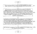
- FIG. 7 is a flowchart showing the determination process to determine transfer current
- FIG. 8 is a view showing transfer characteristics
- FIG. 9 is a view showing transfer characteristics and back-transfer characteristics
- FIG. 10 is a graph showing transfer characteristics including back-transfer in a plurality of transfer members
- FIG. 11 is a view showing details of ST 1 in FIG. 7 ;
- FIG. 12 is a view showing a third toner image
- FIG. 13 is a view showing details of ST 2 in FIG. 7 ;
- FIG. 14 is a view showing details of ST 3 in FIG. 7 ;
- FIG. 15 is a graph showing transfer-back characteristic
- FIG. 16 is a view showing back-transfer amount and transfer toner amount.
- FIG. 3 is a view showing the entire constitution of an image forming apparatus according to the embodiment of the present invention.
- the image forming apparatus shown in FIG. 1 is referred to as a tandem-type color image forming apparatus, incorporating an automatic document conveyance member 30 , an image reading device 60 , exposure devices 3 Y, 3 M, 3 C, and 3 K, drum-shaped photoreceptors 1 Y, 1 M, 1 C, and 1 K, charging devices 2 Y, 2 M, 2 C, and 2 K, developing members 4 Y, 4 M, 4 C, and 4 K, a fixing device 24 , a belt-shaped intermediate transfer body 6 , sheet feeding members 21 A, 21 B, and 21 C, and a conveyance system 22 .
- the automatic document conveyance member 30 is a member to automatically convey a double-sided or single-sided document d.
- the image reading device 60 is a device to read image information using a movable optical system in which images of a large number of documents d fed from the document platen are focused on an imaging element 60 A incorporating a CCD to be read using a reading optical system 60 B having 3 movable mirrors and an imaging lens.
- a toner image forming section 10 Y forming a yellow toner image, has a photoreceptor 1 Y, a charging device 2 Y, an exposure device 3 Y, a developing member 4 Y, a lubricant coating device 5 Y, and a photoreceptor cleaning device 8 Y.
- a toner image forming section 10 M forming a magenta toner image, has a photoreceptor 1 M, a charging device 2 M, an exposure device 3 M, a developing member 4 M, a lubricant coating device 5 M, and a photoreceptor cleaning device 8 M.
- a toner image forming section 10 C forming a cyan toner image, has a photoreceptor 1 C, a charging device 2 C, an exposure device 3 C, a developing member 4 C, a lubricant coating device 5 C, and a photoreceptor cleaning device 8 C.
- a toner image forming section 10 K forming a black toner image, has a photoreceptor 1 K, a charging device 2 K, an exposure device 3 K, a developing member 4 K, a lubricant coating device 5 K, and a photoreceptor cleaning device 8 K.
- the charging device 2 Y and the exposure device 3 Y, the charging device 2 M and the exposure device 3 M, the charging device 2 C and the exposure device 3 C, and the charging device 2 K and the exposure device 3 K each constitute a latent image forming member.
- the intermediate transfer body 6 as the transfer body is an endless belt, and stretched and supported by a plurality of rollers, moving as shown by the arrow.
- Transfer members 7 Y, 7 M, 7 C, and 7 K each having a primary, transfer roller transfer toner images having been formed in the toner image forming sections 10 Y, 10 M, 10 C, and 10 K onto the moving intermediate transfer body 6 .
- the intermediate transfer body 6 orbits clockwise as shown by the arrow.
- the toner image forming section 10 Y, the toner image forming section 10 M, the toner image forming section 10 C, and the toner image forming section 10 K are arranged in this sequential order from the upstream side with respect to the moving direction of the intermediate transfer body 6 .
- the transfer member 7 Y, the transfer member 7 M, the transfer member 7 C, and the transfer member 7 K are arranged in this sequential order from the upstream side with respect to the moving direction of the intermediate transfer body 6 .
- Signals of image information having been focused on the imaging element 60 A are sent to an unshown image processing section.
- the image processing section carries out analog processing, VD conversion, shading correction, and image compression processing to then send the signal of each color to the exposure devices 3 Y, 3 M, 3 C, and 3 K.
- a semiconductor laser serving as a laser light source is used in the exposure devices 3 Y, 3 M, 3 C, and 3 K.
- a light beam having been ejected from the semiconductor laser is formed as a scanning light beam by an optical element such as a polygon mirror to enter the photoreceptors 1 Y, 1 M, 1 C, and 1 K as scanned bodies and thereby electrophotographic latent images of the individual colors are formed.
- Toner images of the individual colors having been formed in the toner image forming sections 10 Y, 10 M, 10 C, and 10 K are sequentially transferred onto the rotating intermediate transfer body 6 by the transfer members 7 Y, 7 M, 7 C, and 7 K to form a composed color image.
- a recording medium S stored in any of the sheet feeding cassettes 20 A, 20 B, and 20 C is fed by a corresponding one of the sheet feeding members 21 A, 21 B, and 21 C and passed through the conveyance System 22 , followed by being conveyed to a secondary transfer section with right timing by a registration roller 23 to transfer the color image onto the recording medium S in the secondary transfer device 7 A.
- the recording medium S on which the color image has been transferred is subjected to fixing by the fixing device 24 and nipped by the sheet discharging roller 25 to be stacked on the sheet discharging tray 26 outside the machine.
- the intermediate transfer body 6 having separated the recording medium S is cleaned by the intermediate transfer body cleaning device 9 .
- the toner image farming sections 10 Y, 10 M, 10 C, and 10 K and the intermediate transfer body 6 are incorporated in the image forming apparatus as a removable process unit.
- the IDC is a density sensor to measure the density of a toner image on the intermediate transfer body 6 and has a light emitting element for irradiation of light toward the intermediate transfer body 6 and a light receiving element to receive reflective light from the intermediate transfer body 6 to measure the densities of a yellow toner image, a magenta toner image, a cyan toner image, and a black toner image being formed on the intermediate transfer body 6 .
- FIG. 4 is a block diagram of the control system to set transfer current.
- the control section CR controls the toner image forming sections 10 Y, 10 M, 10 C, and 10 K and the transfer members 7 Y, 7 M, 7 C, and 7 K, and captures an output of the density sensor IDC as density information during controlling.
- the toner image forming section 10 Y has a latent image forming member SY containing a charging device 2 Y and an exposure device 3 Y and a developing member 4 Y.
- the toner image forming section 10 M has a latent image forming member SM containing a charging device 2 M and an exposure device 3 M and a developing member 4 M.
- the toner image forming section 10 C has a latent image forming member SC containing a charging device 2 C and an exposure device 3 C and a developing member 4 C.
- the toner image timing section 10 K has a latent image forming member SK containing a charging device 2 K and an exposure device 3 K and a developing member 4 K.
- FIG. 5 shows the constitution of a transfer member.
- FIG. 5 shows the transfer member 7 Y.
- the transfer members 7 M, 7 C, and 7 K also have the constitution shown in FIG. 5 .
- the transfer member 7 Y incorporates a transfer roller 7 YR, a spring 7 YS, and a power source 7 YE.
- the transfer roller 7 YR is energized by the spring 7 YS to press the intermediate transfer body 6 against the photoreceptor 1 Y.
- the transfer roller 7 YR is formed of a conductive rubber roller, and the power source 7 YE outputs transfer current, which is variable current, to apply a transfer voltage to the transfer roller 7 YR.
- the output current value of the power source 7 YE is changed by changing the duty ratio of pulse current as shown in FIG. 6 .
- the control section CR determines the transfer current in the transfer process to transfer toner images having been formed in the toner image forming sections 10 Y, 10 M, 10 C, and 10 K onto the intermediate transfer body 6 serving as the transfer body, namely, the transfer current each in the transfer members 7 Y, 7 M, 7 C, and 7 K, via a control process as described below.
- FIG. 7 shows the determination process to determine transfer current.
- step ST 1 the developing voltage in the developing member 4 Y of the toner image forming section 10 Y as a first toner image forming section arranged on the most upstream side with respect to the moving direction of the intermediate transfer body 6 is determined.
- the developing voltage is determined to allow the density of a toner image containing a patch image of uniform density formed during determination of transfer current to be appropriate.
- step ST 2 the developing voltage having been determined in ST 1 is set; a toner image containing a patch image is formed on the photoreceptor 1 Y serving as an image carrier in the toner image forming section 10 Y; the toner image is transferred onto the intermediate transfer body 6 by the transfer member 7 Y serving as a first transfer member arranged on the most upstream side with respect to the moving direction of the intermediate transfer body 6 ; and a first toner image is formed on the intermediate transfer body 6 .
- the first toner image forming section is a toner image forming section arranged on the upstream side with respect to the moving direction of the intermediate transfer body 6 as the transfer body, and the first transfer member is a transfer member arranged on the upstream side with respect to the moving direction of the intermediate transfer body 6 .
- the first density of the first toner image is measured by the density sensor IDC, and from the first density, a certain standard density, e.g., the transfer current in the transfer member 7 Y to provide the maximum density is determined.
- transfer current is applied in the transfer member 7 Y.
- transfer members 7 M, 7 C, and 7 K each serving as a second transfer member, transfer is carried out under the condition of no transfer voltage application, namely, under a condition in which only the power source 7 YE of the transfer member 7 Y is switched on and the power sources of the transfer members 7 M, 7 C, and 7 K are switched off.
- the second transfer member is a transfer member arranged on the downstream side with respect to the moving direction of the intermediate transfer body 6 .
- Curve L 1 of FIG. 8 shows a transfer characteristic as the relationship between transfer current and transfer rate, e.g., the toner amount change of a toner image on the intermediate transfer body 6 versus the change of the transfer current in the transfer member 7 Y.
- curve L 1 to a certain value (50 ⁇ A in the figure), with the increase of the transfer current, the toner amount increases, but in the range more than the certain value, with the increase of the transfer current, the toner amount decreases. It is thought that such a saturation phenomenon of the toner amount results from occurrence of back-transfer as shown by curve L 3 due to toner reverse charging via overcurrent.
- the transfer to form a first toner image is carried out, for example, with transfer current having current values of a plurality of levels at intervals of 10 ⁇ A from 10 ⁇ A-70 ⁇ A.
- ST 2 determines a standard density on curve L 1 , e.g., the transfer current at the maximum density.
- step ST 3 a toner image containing a patch image is formed on the photoreceptor 1 Y at the developing voltage having been set in ST 1 ; a transfer voltage with the transfer current having been determined in ST 2 is applied to the transfer member 7 Y and also a transfer voltage is each applied to the transfer members 7 M, 7 C, and 7 K to transfer toner images onto the intermediate transfer body 6 ; and a second toner image is formed on the intermediate transfer body 6 .
- the transfer current determined in ST 2 is one example of predetermined standard transfer current.
- the second density of the second toner image is measured by the density sensor IDC to grasp the transfer characteristics of the transfer members 7 M, 7 C, and 7 K from the second density.
- step ST 4 the transfer currents in the transfer members 7 Y, 7 M, 7 C, and 7 K are determined.
- FIG. 9 shows transfer characteristics and back-transfer characteristics.
- the vertical axis represents the toner amount and the back-transfer amount on the intermediate transfer body 6 .
- the horizontal axis represents the transfer currents of the transfer members 7 Y and 7 M.
- Curve L 1 shows the density change of a toner image formed on the intermediate transfer body 6 when transfer has been carried out in the state of applying a transfer voltage to the transfer member 7 Y and of applying no transfer voltage to the transfer member 7 M, in other words, showing the transfer characteristic as transfer current vs. transfer rate in the transfer member 7 Y.
- Curve L 2 shows the back-transfer characteristic in the transfer member 7 M when transfer has been earned out in the state of applying a transfer voltage to the transfer members 7 Y and 7 M.
- curve L 4 shows the toner amount of a toner image formed in the intermediate transfer body 6 when transfer has been earned out in the state of applying a transfer voltage to the transfer members 7 Y and 7 M, in other words, showing the transfer characteristic including back-transfer in the transfer member 7 M.
- Curve 4 can be referred to as one formed from the value obtained by subtracting curve L 2 from curve L 1 .
- the transfer characteristics shown in FIG. 9 are characteristics when as the same transfer current is allowed to flow in the transfer member 7 Y and the transfer member 7 M, the transfer current is changed.
- curve L 4 representing a transfer characteristic
- the toner amount of a toner image on the intermediate transfer body 6 more largely decreases than in curve L 1 due to back-transfer in the transfer member 7 M with the increase of the transfer current.
- FIG. 10 is a graph showing the transfer characteristics including back-transfer in a plurality of transfer members.
- the vertical axis represents the toner amount and the back-transfer amount on the intermediate transfer body 6 .
- the horizontal axis represents the transfer currents of the transfer members 7 Y, 7 M, 7 C, and 7 K.
- FIG. 10 shows the situation that a toner image having been formed in the toner image forming section 10 Y is passed through the transfer member on the downstream side and transferred onto the intermediate transfer body 6 and then the toner amount of a toner image formed on the intermediate transfer body 6 is decreased due to back-transfer in the transfer member on the downstream side.
- Curve L 4 , curve L 5 , and curve L 6 represent the transfer characteristic including back-transfer of the transfer member 7 M, the transfer characteristic of the transfer member 7 C including back-transfer of the transfer members 7 M and 7 C, and the transfer characteristic of the transfer member 7 K including back-transfer of the transfer members 7 M, 7 C, and 7 K, respectively.
- the difference between curve L 1 and curve L 4 represents the back-transfer characteristic of the transfer member 7 M.
- the difference between curve L 4 and curve L 5 represents the back-transfer characteristic of the transfer member 7 C.
- the difference between curve L 5 and curve L 6 represents the back-transfer characteristic of the transfer member 7 K.
- curve L 1 is one obtained via measurement by the density sensor IDC when transfer has been carried out in the state of applying a transfer voltage in the transfer member 7 Y and no transfer voltage in the transfer members 7 M, 7 C, and 7 K.
- Curve L 4 is one obtained via measurement by the density sensor IDC when transfer has been carried out in the state of applying a transfer voltage in the transfer members 7 Y and 7 M and no transfer voltage in the transfer members 7 C, and 7 K.
- Curve L 5 is one obtained via measurement by the density sensor IDC when transfer has been carried out in the state of applying a transfer voltage in the transfer members 7 Y, 7 M, and 7 C and no transfer voltage in the transfer member 7 K
- Curve L 6 is one obtained via measurement by the density sensor IDC when transfer has been carried out in the state of applying a transfer voltage in the transfer member 7 Y, 7 M, 7 C, and 7 K.
- the transfer characteristics shown in FIG. 10 are also characteristics when as the same transfer current is allowed to flow in the transfer members 7 Y, 7 M, 7 C, and 7 K, the transfer current is changed, in the same manner as in the transfer characteristics of FIG. 9 .
- step ST 4 the control section CR determines the transfer currents in the transfer members 7 Y, 7 M, 7 C, and 7 K from the transfer characteristics shown in FIG. 10 , namely, from curves L 1 , L 4 , L 5 , and L 6 .
- Determination of the transfer current is made based on the following 3 points as the basis of judgment. (1) Transfer rate is increased as much as possible to ensure the density of a toner image. (2) The variation of the color shade of a color image is inhibited. Since the color of a color image is determined by the amount ratio of color toners to form a color image, a consideration is made so that the amount ratio among a yellow toner, a cyan toner, and a magenta toner is not changed to determine transfer current
- toner images are superimposed in order of a yellow toner image, a magenta toner image, a cyan toner image, and a black toner image.
- transfer current is set so as for back-transfer to decrease to a maximum extent.
- the transfer current of the most upstream side transfer member be maximized and the transfer currents of the downstream side transfer members be at most the transfer current of the most upstream side transfer member.
- the transfer currents having been determined via the above process occasionally deviate from a current value to form a toner image of maximum density at maximum transfer rate. In this case, namely, since the transfer currents have been set with a deviation from a current value to maximize transfer rate, the density of a toner image is decreased. To compensate this density decrease, a correction is made so as to form a toner image of maximum density in development.
- control section CT refers to the thus-produced table for determination.
- the control section CR forms a toner image for image stabilizing control, detects the density of the formed toner image, and then carries out image stabilizing control to control the exposure amount in the exposure device and the developing voltage in the developing member based on the detected density.
- image stabilizing control is described in, for example, Unexamined Japanese Patent Application Publication Nos. 2006-189562 and 2007-65269.
- FIG. 11 shows details of ST 1 in FIG. 7 .
- step ST 10 the developing voltage of the developing member 4 Y of the toner image forming section 10 Y is set.
- the developing voltage set here has values of a plurality of levels having been previously determined.
- step ST 11 the transfer current in the transfer member 7 Y is set. This transfer current has a current value of a single level having been previously determined.
- step ST 12 under a condition formed by the developing voltage having been set in ST 10 and the transfer current having been set in ST 11 , a latent image is formed on the photoreceptor 1 Y and then a toner image is formed by development to form a third toner image on the intermediate transfer body 6 via transfer.
- FIG. 12 shows a third toner image.
- the third toner image is formed on the intermediate transfer body 6 in such a manner that exposure is carried out at maximum exposure amount or saturated exposure amount to form a latent image, which is then developed at developing voltages of a plurality of levels and transferred. As shown in FIG. 12 , a plurality of patch images having different densities corresponding to the developing voltages are contained.
- step ST 13 the density sensor MC detects the third density of the third toner image.
- step ST 14 on the basis of the detection result of the density sensor IDC, the developing voltage to form a toner image of appropriate density is determined (ST 14 ).
- the developing voltage determined in ST 14 is a voltage of a single level to form a toner image of appropriate density at the maximum exposure amount.
- FIG. 13 shows details of ST 2 in FIG. 7 .
- step ST 20 the developing voltage in the developing member 4 Y and the transfer current in the transfer member 7 Y are set.
- the developing voltage to be set is the one having been determined in ST 14 in FIG. 11 . Further, the transfer current to be set is a transfer current of a plurality of levels having been previously set.
- a first toner image is formed on the intermediate transfer body 6 .
- the first toner image contains a plurality of patch images having different densities of a plurality of levels corresponding to the transfer current of a plurality of levels, resembling the third toner image shown in FIG. 12 .
- transfer current is applied in the transfer member 7 Y but no transfer current is applied in the transfer members 7 M, 7 C, and 7 K.
- the density sensor IDC measures the first density of the first toner image.
- step ST 22 a certain standard density, for example, transfer current providing maximum density is determined from the first density having been measured in ST 22 .
- the first density of the first toner image is, for example, the density to form curve L 1 in FIGS. 8 , 9 , and 10 , determining the transfer current providing maximum density and also capturing the transfer characteristic of the transfer member 7 Y as in curve L 1 .
- FIG. 14 shows details of ST 3 of FIG. 7 .
- a toner image is formed on the photoreceptor 1 Y at the developing voltage having been determined in ST 14 of FIG. 11 , and then via application of a transfer voltage at the transfer current in the transfer member 7 Y having been determined in ST 22 of FIG. 13 and of a transfer voltage in the transfer member 7 M which is the transfer member on the downstream side, transfer is carried out.
- the transfer current in the transfer member 7 M has current values of a plurality of levels. Therefore, the second toner image contains a plurality of patch images having different densities corresponding to the transfer current of a plurality of levels in the transfer member 7 M, resembling the third toner image shown in FIG. 12 .
- the density sensor DC measures the second density of the second tone image. Based on density measurement of ST 31 , the second density changing with the change of the transfer current in the transfer member 7 M is acquired.
- FIG. 15 shows this density change.
- curve L 7 shows the second density of the second toner image on the intermediate transfer body 6 in which the transfer current of the transfer member 7 Y is set at the value to form maximum density Dmax in FIG. 10 and then the transfer current of the transfer member 7 M is allowed to widely change.
- the second density will decrease via back-transfer, decreasing with the increase of the transfer current in the transfer member 7 M.
- the control section CR forms curve L 4 in FIG. 10 from curve L 7 and then captures the transfer characteristic of the transfer member 7 M.
- curve L 4 from curve L 7
- the density decrease rate of curve L 7 in each of the corresponding plural points is multiplied.
- the transfer characteristic grasped in ST 32 is the transfer characteristic of a toner image in which a toner image having been formed in the toner image torturing section 10 Y is transferred onto the intermediate transfer body 6 by the transfer member 7 Y and passed through the transfer member 7 M to be formed on the intermediate transfer body 6 , namely, being the transfer characteristic of the transfer member 7 M.
- the transfer characteristic of the transfer member 7 M is grasped in which the transfer member 7 Y is assigned as a first transfer member on the upstream side and the transfer member 7 M is assigned as a second transfer member on the downstream side.
- the transfer member 7 Y is assigned as a first transfer member on the upstream side and the transfer members 7 M and 7 C are assigned as second transfer members on the downstream side to execute ST 30 -ST 32 . Further, the transfer member 7 Y is assigned as a first transfer member on the upstream side and the transfer members 7 M, 7 C, and 7 K are assigned as second transfer members on the downstream side to execute ST 30 -ST 32 .
- step ST 30 -ST 33 are repeated, and then in the stage where the transfer characteristics of the transfer members 7 C and 7 K, namely, the transfer characteristics shown by curves L 5 and L 6 of FIG. 10 have been grasped (Y of ST 33 ), i.e., in step ST 34 , the transfer current in each of the transfer members 7 Y, 7 M, 7 C, and 7 K is determined from the grasped transfer characteristics shown by curves L 1 , L 4 , L 5 , and L 6 .
- the transfer members 7 M, 7 C, and 7 K are applied with, a transfer voltage using transfer current having current values of a plurality of levels to grasp the transfer characteristic shown by curve L 6 of FIG. 10 , namely, a transfer characteristic including back-transfer in the transfer members 7 M, 7 C, and 7 K.
- transfer current can also be determined.
- the toner image forming section 10 Y is assigned as the toner image fanning section on the most upstream side and the transfer member 7 Y is assigned as the transfer member on the most upstream side to form a yellow toner image and via the above process, with respect to the yellow toner image, the transfer characteristic of the transfer member 7 Y and a transfer characteristic including back-transfer in the downstream are grasped. Then, with respect to a magenta toner image, the transfer characteristic of the transfer member 7 M which is the transfer member on the most upstream side and a transfer characteristic including back-transfer in the downstream are grasped.
- the transfer characteristic of the transfer member 7 C which is the transfer member on the most upstream side and a transfer characteristic including back-transfer in the downstream are grasped.
- the transfer characteristic of the transfer member 7 K is grasped.
- the transfer currents of the transfer members 7 Y, 7 M, 7 C, and 7 K are determined.
- Table 1 shows one example of the transfer current determined by the above-described transfer current control process.
- transfer current is preferably set at a left-leaning point to a maximum extent on each curve in FIG. 10 .
- the transfer current is set.
- curves L 1 , L 4 , L 5 , and L 6 on the left side of 50 ⁇ A, as the transfer current decreases, the transfer rate also decreases, and therefore, in consideration of ensuring of the transfer rate and color shade variation, the transfer current is determined.
- the transfer current is determined so as for the transfer rate to increase as much as possible.
- developing density is increased to compensate image density decrease due to the low transfer rate.
- the increase of the transfer rate makes it possible that the developing density is controlled at a low level, resulting in controlling toner consumption.
- FIG. 16 shows the amount of a toner having been transferred onto the intermediate transfer body (transferred toner amount) and back-transfer amount.
- the transferred toner amount is smallest and the back-transfer amount is largest.
- the transferred toner amount is largest and the back-transfer amount is small.
- the transferred toner amount is of a medium level and the back-transfer amount is small.
- the transfer current in a transfer member is determined.
Landscapes
- Physics & Mathematics (AREA)
- General Physics & Mathematics (AREA)
- Engineering & Computer Science (AREA)
- Microelectronics & Electronic Packaging (AREA)
- Electrostatic Charge, Transfer And Separation In Electrography (AREA)
- Dry Development In Electrophotography (AREA)
Abstract
Description
- (1) To achieve at least one of the above mentioned objects, an image forming apparatus reflecting one aspect of the present invention includes a plurality of toner image forming sections; a transfer body; a plurality of transfer members, each of which is provided corresponding to each of the toner image forming sections, to transfer toner images formed in the toner image forming sections onto the transfer body; a density sensor, arranged on a downstream side of the transfer members with respect to a moving direction of the transfer body, to measure a density of a toner image on the transfer body; and
- (2) In the abovementioned image forming apparatus of
item 1,
- (3) In the abovementioned image forming apparatus of
item 1 oritem 2,
- (4) In the abovementioned image forming apparatus in any of items 1-3,
- (5) In the abovementioned image forming apparatus of item 4, wherein the control section determines the transfer current from the first transfer characteristic and the second transfer characteristic.
- (6) In the abovementioned image forming apparatus in any of items 1-5,
- (7) In the abovementioned image forming apparatus in any of items 1-6, wherein the control section determines the transfer current in the second transfer member is smaller than the transfer current in the first transfer member.
- (8) In the abovementioned image forming apparatus of item 4, wherein a number of the plurality of the toner image forming sections is three or more, a number of the plurality of the transfer members is three or more and the control section grasps the first transfer characteristic of the first transfer member and the second transfer characteristic of the second transfer member wherein the transfer member on a most upstream side is assigned as the first transfer member and the transfer member on a most downstream side is assigned as the second transfer member and estimates a transfer characteristic of the transfer member between the transfer member on the most upstream side and the transfer member on the most downstream side from the grasped first transfer characteristic and the second transfer characteristic.
- (9) In the abovementioned image forming apparatus in any of items 1-8, wherein the control section determines the transfer currents in the first transfer member and the second transfer member and thereafter sets a developing voltage in a developing member.
| TABLE 1 | ||||
| Color | Yellow | Magenta | | Black |
| A | ||||
| 60 μA | 60 μA | 60 μA | 60 μA | |
| B | 55 μA | 58 μA | 60 μA | 50 μA |
| C | 55 μA | 55 μA | 55 μA | 50 μA |
Claims (9)
Applications Claiming Priority (3)
| Application Number | Priority Date | Filing Date | Title |
|---|---|---|---|
| JP2011013893A JP5625951B2 (en) | 2011-01-26 | 2011-01-26 | Image forming apparatus |
| JP2011-013893 | 2011-01-26 | ||
| JPJP2011-013893 | 2011-01-26 |
Publications (2)
| Publication Number | Publication Date |
|---|---|
| US20120189333A1 US20120189333A1 (en) | 2012-07-26 |
| US8676070B2 true US8676070B2 (en) | 2014-03-18 |
Family
ID=46544247
Family Applications (1)
| Application Number | Title | Priority Date | Filing Date |
|---|---|---|---|
| US13/353,361 Expired - Fee Related US8676070B2 (en) | 2011-01-26 | 2012-01-19 | Image forming apparatus |
Country Status (2)
| Country | Link |
|---|---|
| US (1) | US8676070B2 (en) |
| JP (1) | JP5625951B2 (en) |
Families Citing this family (3)
| Publication number | Priority date | Publication date | Assignee | Title |
|---|---|---|---|---|
| JP5361982B2 (en) * | 2011-12-19 | 2013-12-04 | キヤノン株式会社 | Image forming apparatus |
| JP5908387B2 (en) * | 2012-10-31 | 2016-04-26 | 京セラドキュメントソリューションズ株式会社 | Transfer device and image forming apparatus having the same |
| JP6122989B2 (en) * | 2016-03-23 | 2017-04-26 | 京セラドキュメントソリューションズ株式会社 | Transfer device and image forming apparatus having the same |
Citations (5)
| Publication number | Priority date | Publication date | Assignee | Title |
|---|---|---|---|---|
| US6564021B1 (en) * | 1999-09-29 | 2003-05-13 | Canon Kabushiki Kaisha | Image forming apparatus with transfer voltage control for transferring toner patterns |
| JP2006189562A (en) | 2005-01-05 | 2006-07-20 | Konica Minolta Business Technologies Inc | Image forming apparatus |
| JP2007065269A (en) | 2005-08-31 | 2007-03-15 | Konica Minolta Business Technologies Inc | Image forming method and image forming apparatus |
| JP2007241117A (en) | 2006-03-10 | 2007-09-20 | Ricoh Co Ltd | Image forming apparatus |
| US20110222128A1 (en) * | 2010-03-12 | 2011-09-15 | Yuji Wada | Image forming apparatus and image forming method |
Family Cites Families (2)
| Publication number | Priority date | Publication date | Assignee | Title |
|---|---|---|---|---|
| JP4454806B2 (en) * | 2000-07-18 | 2010-04-21 | キヤノン株式会社 | Image forming apparatus |
| JP2009294525A (en) * | 2008-06-06 | 2009-12-17 | Ricoh Co Ltd | Image forming apparatus |
-
2011
- 2011-01-26 JP JP2011013893A patent/JP5625951B2/en not_active Expired - Fee Related
-
2012
- 2012-01-19 US US13/353,361 patent/US8676070B2/en not_active Expired - Fee Related
Patent Citations (5)
| Publication number | Priority date | Publication date | Assignee | Title |
|---|---|---|---|---|
| US6564021B1 (en) * | 1999-09-29 | 2003-05-13 | Canon Kabushiki Kaisha | Image forming apparatus with transfer voltage control for transferring toner patterns |
| JP2006189562A (en) | 2005-01-05 | 2006-07-20 | Konica Minolta Business Technologies Inc | Image forming apparatus |
| JP2007065269A (en) | 2005-08-31 | 2007-03-15 | Konica Minolta Business Technologies Inc | Image forming method and image forming apparatus |
| JP2007241117A (en) | 2006-03-10 | 2007-09-20 | Ricoh Co Ltd | Image forming apparatus |
| US20110222128A1 (en) * | 2010-03-12 | 2011-09-15 | Yuji Wada | Image forming apparatus and image forming method |
Also Published As
| Publication number | Publication date |
|---|---|
| JP5625951B2 (en) | 2014-11-19 |
| JP2012155127A (en) | 2012-08-16 |
| US20120189333A1 (en) | 2012-07-26 |
Similar Documents
| Publication | Publication Date | Title |
|---|---|---|
| US8107837B2 (en) | Image forming apparatus, control method thereof, program and recording medium | |
| US8249474B2 (en) | Image forming apparatus which controls image forming conditions based on residual toner of a detection pattern | |
| JP6819171B2 (en) | Image formation system and control program | |
| JPH11102091A (en) | Image forming device | |
| GB2257658A (en) | Control of photoconductive image forming apparatus. | |
| US7587149B2 (en) | Image forming apparatus and method for controlling the same | |
| US8676070B2 (en) | Image forming apparatus | |
| US20140133875A1 (en) | Image forming apparatus | |
| US6285839B1 (en) | Image forming apparatus having function for automatically adjusting image forming condition | |
| JP2012008577A (en) | Image forming apparatus | |
| EP2474863B1 (en) | Image forming apparatus, image forming control method and image forming control program | |
| US7151902B2 (en) | Toner transfer technique | |
| JP2015166846A (en) | Control device for determining exposure amount used for image formation, and image forming apparatus using the same | |
| US20190137919A1 (en) | Image forming system, image forming apparatus, tone correction method, non-transitory recording medium storing computer readable tone correction program, and image density correction method | |
| JP6945998B2 (en) | Image forming device, control method of image forming device | |
| US20120002990A1 (en) | Image forming apparatus and image forming method | |
| US20110262157A1 (en) | Image forming apparatus and image stabilization control method in image forming apparatus | |
| JP2007003707A (en) | Image forming apparatus and program | |
| CN102135742A (en) | image forming device | |
| JP5821296B2 (en) | Image forming apparatus | |
| US9291962B2 (en) | Image-forming apparatus with controller and fixing portion to control toner adhesion amount | |
| JP2009042432A (en) | Image forming apparatus | |
| JP2014071433A (en) | Image forming apparatus | |
| US11480905B2 (en) | Image forming apparatus | |
| JP2011158837A (en) | Image forming apparatus and image forming method |
Legal Events
| Date | Code | Title | Description |
|---|---|---|---|
| AS | Assignment |
Owner name: KONICA MINOLTA BUSINESS TECHNOLOGIES, INC., JAPAN Free format text: ASSIGNMENT OF ASSIGNORS INTEREST;ASSIGNORS:KOSHIMURA, YASUSHI;ISHIZUKA, KAZUTERU;REEL/FRAME:027557/0549 Effective date: 20111220 |
|
| FEPP | Fee payment procedure |
Free format text: PAYOR NUMBER ASSIGNED (ORIGINAL EVENT CODE: ASPN); ENTITY STATUS OF PATENT OWNER: LARGE ENTITY |
|
| STCF | Information on status: patent grant |
Free format text: PATENTED CASE |
|
| MAFP | Maintenance fee payment |
Free format text: PAYMENT OF MAINTENANCE FEE, 4TH YEAR, LARGE ENTITY (ORIGINAL EVENT CODE: M1551) Year of fee payment: 4 |
|
| MAFP | Maintenance fee payment |
Free format text: PAYMENT OF MAINTENANCE FEE, 8TH YEAR, LARGE ENTITY (ORIGINAL EVENT CODE: M1552); ENTITY STATUS OF PATENT OWNER: LARGE ENTITY Year of fee payment: 8 |
|
| FEPP | Fee payment procedure |
Free format text: MAINTENANCE FEE REMINDER MAILED (ORIGINAL EVENT CODE: REM.); ENTITY STATUS OF PATENT OWNER: LARGE ENTITY |
|
| LAPS | Lapse for failure to pay maintenance fees |
Free format text: PATENT EXPIRED FOR FAILURE TO PAY MAINTENANCE FEES (ORIGINAL EVENT CODE: EXP.); ENTITY STATUS OF PATENT OWNER: LARGE ENTITY |
|
| STCH | Information on status: patent discontinuation |
Free format text: PATENT EXPIRED DUE TO NONPAYMENT OF MAINTENANCE FEES UNDER 37 CFR 1.362 |